

thin_section_microscopy
.pdfRaith, Raase, Reinhardt – January 2011
Guide to Thin Section Microscopy |
Exsolution textures |
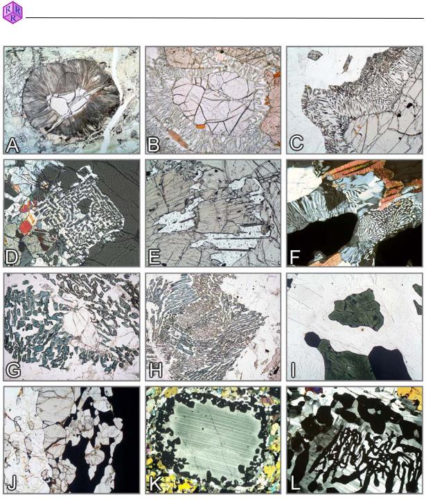
Figure 3.4-2: Exsolution
A: Augite twin on (100) with pigeonite lamellae on (001); B: Bronzite with thin augite lamellae on (100); C: Exsolution lamellae in grunerite; D-H: Perthitic unmixing in alkali feldspars: mesoperthite, film-like spindle perthite, network-like vein perthite; spindle perthite; coarse vein perthite; I,J: Antiperthitic unmixing in plagioclase; K,L: Embayed platelets and drop-like crystals of exsolved dolomite in calcite host; M-O: Oriented precipitation of ilmenite platelets in orthopyroxene (M) and biotite (N), and rutile needles in garnet (O).
45
Raith, Raase, Reinhardt – January 2011
Guide to Thin Section Microscopy |
Reaction textures |
Figures 3.4-3: Reaction textures in granulites
A-F: Garnet breakdown – A. Radiating Hbl-Opx-Spl kelyphite fringe (garnet peridotite); B,C. Opx+Crd symplectite (Grt+Qz o Opx+Crd; metapelite; Namibia, Lappland); D. Opx-Sil symplectite (Grt+Qz o Opx+Sil; Mg-Al granulite, Kola Peninsula); E. Opx-Spr symplectite (Grt+”Mg” o Opx+Spr; Mg-Al granulite, Eastern Ghats, India); F. Crd-Qz symplectite (metapelite, Lapland); G,H: Breakdown of sillimanite to form Spr-Crd symplectite (Opx+Sil o Spr+Crd; Mg-Al granulite, southern India); I: Hercynite (Mt unmixing, ilmenite), with finely pigmented cordierite rim in mesoperthite-quartz matrix (Spl+Qz o Crd; metapelite, southern Madagascar); J: Sil+Grt double seam between nearly opaque spinel and quartz (Spl+Qz o Grt+Sil; Fe-Al granulite, Eastern Ghats, India); K,L: Coronitic and skeletal garnet formation in plagioclase (Cpx+Fa+Pl o Grt; ferrodiorite, Eastern Ghats, India).
Mineral abbreviations after Whitney & Evans (American Mineralogist, 95, 185–187, 2010).
46

Guide to Thin Section Microscopy |
Reaction textures |
Raith, Raase, Reinhardt – January 2011
Figure 3.4-4: Reaction textures in granulites and HPto UHP-metamorphic rocks
A. Garnet coronas around clinopyroxene (Cpx+Pl o Grt+Qz; calcsilicate rock, Eastern Ghats Belt, India); B: Monticellite+wollastonite symplectite (åkermanite o Mtc+Wol; calcsilicate rock, Adirondacks, USA); C. Anorthite+calcite symplectite (meionite o An+Cal; calcsilicate rock, Eastern Ghats Belt, India); D: Cal+Qz aggregate (Wol+CO2 o Cal+Qz, South Norway); E: Periclase with brucite fringe (Per+H2O o Bru; calcsilicate marble, Bad Harzburg, Germany); F: Diopside corona around forsterite (Fo+Cal+CO2 o Di+Dol, marble, South Madagascar); G: Pseudomorphic replacement of corundum by spinel (Crn+”MgO” o Spl; Corundum-anorthite rock, South Madagascar); H: Fayalite+quartz symplectite (ferrosilite o Fa+Qz; Eastern Ghats Belt, India); I,J: Polymorphic transformation coesite o quartz (Dora Maira, Western Alps); K,L: Reaction omphacite+quartz o diopside+albite (eclogite; Saualpe, Austria).
Mineral abbreviations after Whitney & Evans (American Mineralogist, 95, 185–187, 2010).
47
Raith, Raase, Reinhardt – January 2011
Guide to Thin Section Microscopy |
Alteration textures |
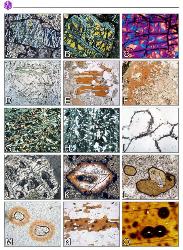
Figure 3.4-5: Secondary alteration products and other features
A-C. Serpentinisation: forsterite o serpentine+magnetite; D,E. Chloritisation: garnet, biotite; F. Reaction clinopyroxene o amphibole; G. Saussuritisation: plagioclase o clinozoisite+albite; H. Sericitisation: plagioclase o muscovite; I,J. Pinitisation: cordierite o muscovite (pinite); K. Breakdown of olivine to “iddingsite” (goethite and clay minerals); L. Kaersutitic amphibole with microcrystalline alteration seam of magnetite+clinopyroxene (opacite); M-O. Pleochroic haloes around zircon and monazite inclusions in cordierite (M) and biotite (N,O).
48

Raith, Raase, Reinhardt – January 2011
Guide to Thin Section Microscopy |
Optical properties: basic principles |
4. Optical properties
4.1 Some basic principles
4.1.1 Nature of light, refraction
In order to describe the interaction of light rays with matter, two physical models can be applied: (a) light as a wave, and (b) light as energy quanta. Most optical phenomena which are observed during microscopic investigation of amorphous or crystalline substances (glass phase, minerals), can be adequately explained with the wave model.
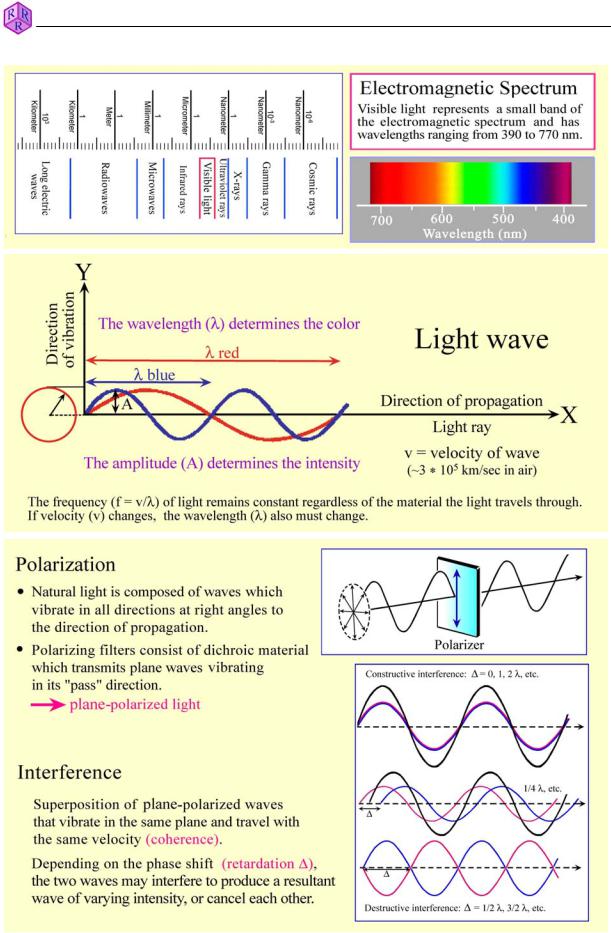
Wave model: Light rays propagate as electromagnetic waves. In each wave electric and magnetic vectors oscillate orthogonal to each other and orthogonal to the propagation direction. The optical behaviour of light when passing through amorphous or crystalline substances is essentially controlled by the interaction of the electric vector with the electric field of the ions. Interactions with the magnetic vector are negligible. Thus, each light wave can be described as a harmonic oscillation [y = A sin(ij*t)] (Fig. 4.1.1-1).
Colour: The human eye can only see a small part of the large spectrum of electromagnetic radiation, namely the spectral domain between about 400 and 800 nm (visible light). This is the colour spectrum from violet to blue, green, yellow, orange and red (Fig. 4.1.1-1). Sunlight consists of various proportions of these colours, the combination of which is perceived as white light. In thin section, colour effects are caused if the spectral composition of originally white light is changed as light passes minerals, either by depletion of specific wavelengths (absorption), or by dispersion of white light as a result of refraction or diffraction of light at grain boundaries, inclusions and rough surfaces.
Intensity: The intensity of light, of a specific colour, for example, is determined by the amplitude of the light wave. It can be modified by absorption.
Polarization: Sunlight or the light emitted from the light source in the microscope consists of waves which vibrate in random directions. In plane-polarized light, the light waves vibrate in a defined direction. Plane-polarized light is generated in modern microscopes by a polarization filter which reduces light of random vibration directions from natural or artificial sources to light of a single vibration direction (Fig. 4.1.1-1). The bundle of light waves entering the thin section consists entirely of E-W vibrating light waves if the polarizer is adjusted precisely.
Interference: Two coherent light waves generated by the same light source can overlap (i.e., interfere) if they vibrate in the same plane and have the same velocity. This is realised in optically anisotropic minerals when the two orthogonally vibrating light rays, generated through double refraction in the crystal plate, are brought to interference in the analyzer after leaving the thin section (see Ch. 4.4). The degree of phase shift (retardation ') determines whether the interfering waves are eliminated or produce a resultant wave of decreased or increased intensity (Fig. 4.1.1-1). If certain sections of the white light spectrum are eliminated, diminished or amplified, interference colours are generated (see Ch. 4.2.3).
49
Raith, Raase, Reinhardt – January 2011
Guide to Thin Section Microscopy |
Optical properties: basic principles |
|
|
|
|
|
|
|
|
|
|
|
|
Figure 4.1.1-1: Wave model of light.
50
Guide to Thin Section Microscopy |
Optical properties: basic principles |
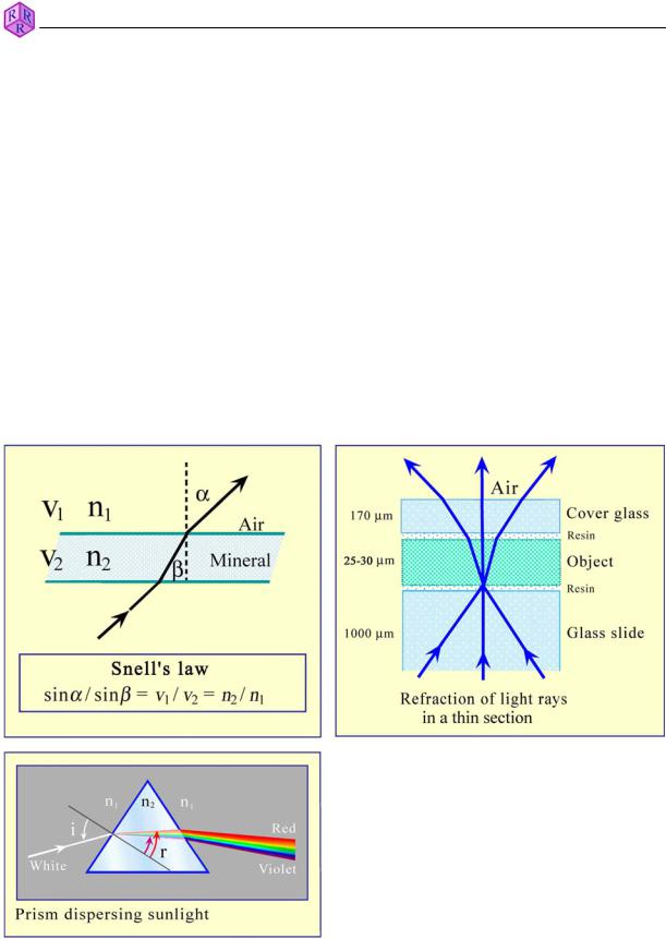
Refraction of light: The velocity of light (as measured in air) is reduced if it enters substances of higher density (liquids, glasses, minerals). If the angle between the incident light rays and the phase boundary (e.g., air/glass) is different from 90°, the light rays change the propagation direction; they are refracted. Snell's Law of refraction applies (Fig. 4.1.1-2) as long as the materials involved are isotropic (cf. Ch. 4.1.2). In a thin section, the object (d = 25 µm) lies embedded between epoxy resin and glass. As light velocity is almost identical in glass and epoxy resin, refraction occurs mainly at boundary surfaces between the object and epoxy resin, but also at phase boundaries within the object (Fig. 4.1.1-2).
The light velocity v of a specified material is an important parameter for its identification. For technical convenience, the refractive index n is used instead of velocity. The refractive index is defined as the ratio between light velocity v0 in vacuum (about the same as in air) and light velocity in the material studied. In isotropic materials, it can be determined experimentally by measuring the angles of refraction Į and ȕ, whereby Snell's Law n2/n1 = sinĮ/sinȕ applies. As light velocities in all solid and liquid substances are smaller than v0 (n1 = nair = 1), refractive indices are generally larger than 1.
Raith, Raase, Reinhardt – January 2011
When passing through a glass prism, rays of white light are “split up” into their spectral colours due to differential refraction at the two prism surfaces. This demonstrates that ray velocity is dependent on wavelength (causing dispersion). Therefore, monochromatic light must be used when determining refractive indices.
Figure 4.1.1-2: Refraction of light, dispersion.
51
Raith, Raase, Reinhardt – January 2011
Guide to Thin Section Microscopy |
Optical properties: basic principles |
4.1.2 Isotropy and anisotropy Isotropic materials
Optically isotropic substances such as gases, liquids, glasses and the highly symmetric cubic minerals show optical behaviour that is independent of the direction of light propagation. This means, their optical properties (light velocity, refractive index and colour) are identical in all directions.
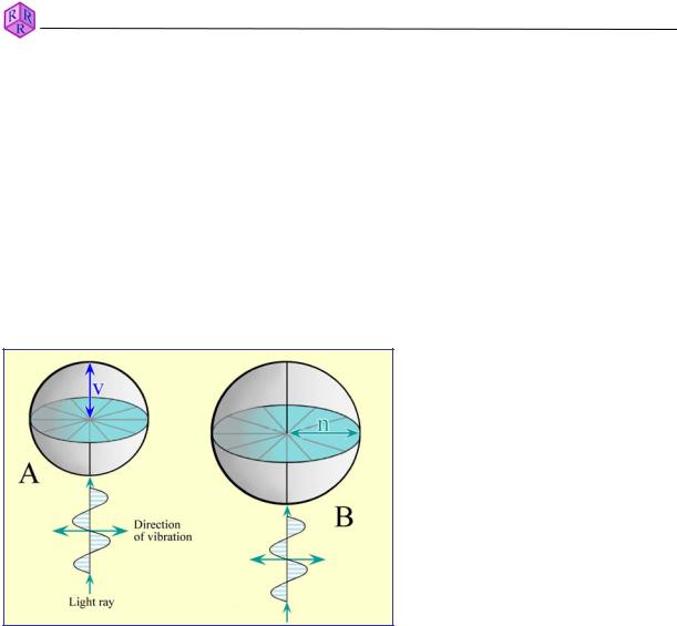
The three-dimensional propagation of light in an isotropic material can be presented graphically as 3-D models for wave or ray velocity and for refractive index, both of which are spheres (Fig. 4.1.2-1). The model preferred by mineralogists is the optical indicatrix, which describes the refractive index as a direction-dependent variable.
Figure 4.1.2-1: Isotropic substances; 3D surfaces of v and n.
A.Ray velocity surface: For each ray direction, the velocity value is represented by a specific distance from a chosen origin (v = 0). The geometric form representing all directions of ray propagation is a sphere with radius v.
B.Indicatrix: For each ray direction, the refractive index is represented by a specific distance from a chosen origin and is marked off parallel to the vibration direction and perpendicular to the ray propagation direction. The geometric form representing the refractive index for all ray propagation directions is a sphere with radius n. Each ray propagation direction has an infinite number of potential vibration directions.
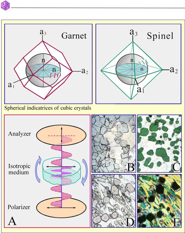
In thin section microscopy, glasses and cubic minerals generally show a single specific refractive index and colour independent of orientation (Fig. 4.1.2-2B-D). An indication of crystal orientation in thin section can therefore only be derived from morphological properties, for example, crystal outlines or cleavage (Fig. 3.1-9). Another important characteristic of optically isotropic materials is that light waves do not experience any change in vibration direction. This means that E-W vibrating plane-polarized light waves maintain their E-W orientation after passing through the isotropic materials (glass, mineral). Therefore, they are blocked by the analyzer, which is a N-S oriented polarizer.
52
Guide to Thin Section Microscopy |
Optical properties: basic principles |
Raith, Raase, Reinhardt – January 2011
Figure 4.1.2-2: Isotropic substances.
Behaviour of light when passing through an isotropic substance (glass or cubic mineral):
In plane-polarized light chemically homogeneous glasses or crystals of cubic minerals show the same colour independent of orientation and rotation of the stage (images B,C: MgFespinel; image D: almandine).
Under crossed polarizers (image A), glass and cubic mineral grains appear black independent of orientation and rotation of the stage (image E: almandine).
53
Raith, Raase, Reinhardt – January 2011
Guide to Thin Section Microscopy |
Optical properties: basic principles |
Anisotropic materials
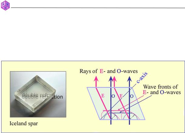
Light propagation in optically anisotropic materials is direction-dependent. All non-cubic crystalline substances are optically anisotropic (Fig. 3.1-1). Light entering an anisotropic crystal is "split" into two light waves that vibrate orthogonal to each other (with exceptions applying to specific directions in the crystal). The two light waves propagate through the crystal with different velocities. This phenomenon is called double refraction (Fig. 4.1.2-3).
Figure 4.1.2-3: Double refraction in a calcite rhombohedron (Huygenian construction).
Crystals of hexagonal, trigonal and tetragonal symmetry
The 3-D models for ray velocities (expressed as v or 1/n) in crystals of hexagonal, trigonal and tetragonal symmetry are therefore double surfaces (Fig. 4.1.2-4A). They illustrate that one of the two light waves (O-wave) propagates like light in an isotropic substance, with the same velocity in all directions, while the other wave (E-wave) changes its velocity dependent on the direction in the crystal. The E-wave has either the highest or lowest value (ve) in the direction normal to the crystallographic c-axis. Any rotation away from this direction, towards the c-axis, will shift ve towards the vo value (decreasing if ve > vo, or increasing if ve < vo). In an orientation parallel c, ve has reached the same value as vo. Thus, in this particular direction, the condition of optical isotropy is realised. This specific direction is referred to as the optic axis. Minerals belonging to the group of hexagonal, trigonal and tetragonal symmetry are optically uniaxial. The vibration directions of the waves are fixed within the crystal: the E-wave vibrates within the plane defined by the ray direction and the c- axis; the O-wave vibrates orthogonal to the E-wave.
Mineralogists prefer the single-surface indicatrix model for explaining optical phenomena over the double-surface model of light propagation. The construction principle is illustrated in Fig. 4.1.2-4B: considering the centre of a crystal as the origin, the refractive indices of two light waves belonging to one wave normal and vibrating orthogonal to each other are marked off in proportional distances from the origin. Thus, a "refraction cross" is created which shows the short and long axes of an ellipse. A construction of the ellipses for all possible wave-normal directions in crystal space results in an ellipsoid which is the indicatrix.
The optical indicatrix of the crystal systems discussed here is an ellipsoid of revolution. It has either a prolate form (ne > no; optically uniaxial positive) or an oblate form (ne < no; optically uniaxial negative) (Fig. 4.1.2-4C,D). The rotation axis (= optical axis) is identical to the c- axis.
54