

thin_section_microscopy
.pdfRaith, Raase, Reinhardt – January 2011
Guide to Thin Section Microscopy |
Microscope |
1.4.3 Conoscopic mode
When a highly convergent light cone is generated (e.g. by inserting the condenser front lens into the light path), bundles of parallel light rays in a wide range of directions pass through the mineral grain. The parallel light rays are then focused in the rear focal plane of the objective, whereby rays with different tilt angles towards the microscope axis produce image points in different positions (Figs. 1.4-1B, 4.2.5-2).
This image therefore allows to examine the behaviour of light propagating along distinct crystallographic directions in a single grain: conoscopic mode. When viewed with crossed polarizers, characteristic interference figures are observed that reflect the symmetry and optical properties of the anisotropic mineral (Ch. 5).
The conoscopic interference figure only records those optical directions that are represented in the aperture cone (Ch. 1.2). In order to maximise the range of directions in a cone as wide as possible, the aperture of both objective and condenser must be large.
An enlarged interference image can be observed by inserting an auxiliary lens, the AmiciBertrand lens, into the tube between analyzer and ocular (Fig. 1.4-1B). The interference image can be focused by adjusting the distance of the ocular to the Amici-Bertrand lens, provided the microscope allows such an adjustment. Some microscopes offer special devices for centring and focusing the Amici-Bertrand lens.
Alternatively, the interference figure can be directly viewed within the microscope tube after removing the ocular, or by looking through a pinhole which replaces the ocular. The image appears smaller and has better contrast compared to an interference figure observed through the Amici-Bertrand lens.
Practical guidance to the conoscopic imaging mode is given in Chapter 5, which also discusses the application of conoscopy to the identification of anisotropic minerals.
1.5 Centring the microscope
Apart from adjusting the substage illumination alignment according to Köhler, an optimal microscope performance requires that all optical components (light source, collector, condenser, objective, ocular) and the rotatable stage are aligned on a common central axis which coincides with the direction of the vertical light rays in the microscope. All components are centred to the axis of the rotating stage. The centring is done in three steps:
A. Centring the objectives
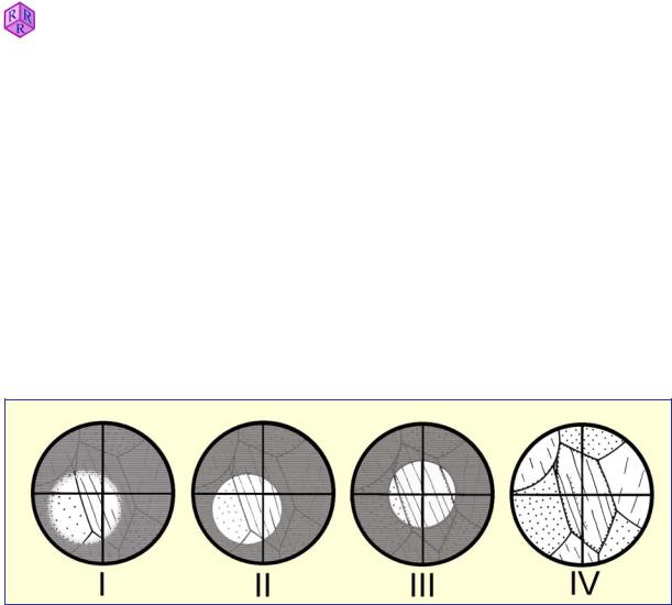
The centre of the field of view, which corresponds to the lens axis of the objective, must be in alignment with the axis of the rotating stage. To check this, the thin section has to be put into focus, a minute grain or object in the sample is selected and shifted to the centre (Fig. 1.5-1, I). When rotating the microscope stage the following situations may occur:
a) The particle remains stationary in its central position, indicating that the objective is precisely centred.
15

Guide to Thin Section Microscopy |
Microscope |
b) The particle is moving along a circular off-centre path (Fig. 1.5-1,II), indicating that the objective is not centred. The rotation axis of the image has to be shifted into the centre of the reticule. This is achieved by turning the two centering screws located in the objective casing or the nosepiece using the centring tools commonly provided with the microscope. Older microscopes may have centring rings on the objectives (and hence no special centring tools are required). The objectives are centred if the rotation centre of any circular particle path coincides with the crosshairs intersection. An alternative way of achieving this is to rotate the stage such that an observed particle is in the most distant off-centre position, 180° from its position at the crosshairs intersection. By turning the centring screws, the particle is then shifted half the distance towards the crosshairs intersection (Fig. 1.5-1,III).
To verify that the objective is precisely centred now, the particle is shifted into the crosshairs intersection by carefully moving the thin section. If the particle remains in its position when rotating the stage, the objective is centred (Fig. 1.5-1,IV). Otherwise, the centring procedure has to be repeated.
All the objectives on the nosepiece have to be centred this way. Should an objective of high magnification be already centred precisely, it is even easier to centre the lower-magnifi- cation objectives. A small grain or object is positioned in the crosshairs intersection using the high-magnification objective. Then the poorly centred objective is rotated into the optical path and the particle is moved to the crosshairs intersection using the centering devices.
Caution! It is important to ensure that the nosepiece is positioned correctly on the tube and the objective in use has clicked into place. Otherwise, centring can never be achieved (Ch. 1.7). Some microscopes (e.g., Olympus) have a stage that can be centred. The stage is then centred on a single fixed objective and has to be aligned first, with that particular objective in place, before the other objectives can be centred. Any attempt to centre the objectives with the stage being off-centre will result in a serious misalignment of the light path.
What applies to all microscopes: To avoid de-centring of the objectives, they must never be touched when changing magnification! Always grab the grooved rim of the nosepiece to change between objectives.
Raith, Raase, Reinhardt – January 2011
Figure 1.5-1: Centring the objective
16
Raith, Raase, Reinhardt – January 2011
Guide to Thin Section Microscopy |
Microscope |
B. Centring the condenser for Köhler illumination
After focusing the thin section, the field diaphragm is closed, the front lens of the condenser inserted into the optical path, and the field diaphragm focused in the image plane by adjusting the substage height (Fig. 1.5-2 I II). The following situations may be encountered:
(a)The centre of the field diaphragm image coincides with the crosshairs intersection, i.e. the centre of the field of view, indicating that the condenser is perfectly centred (Fig. 1.5-2 III).
(b)The field diaphragm image is offset with respect to the crosshairs. In this case, the field diaphragm image must be centred by turning the condenser-centring screws (Fig. 1.5-2 II
III).
Finally, in order to avoid glare by lateral stray light, the field diaphragm should be opened only slightly beyond the margin of the field of view (Fig. 1.5-2 IV).
Figure 1.5-2: Centring the condenser
C. Centring the light source
In modern microscopes, light source and collector are commonly integrated into the base of the microscope and thus need not be centred. In certain microscopes, centring bolts in the lamp case allow to centre the lamp socket. After the condenser has been centred, the lamp position is adjusted until the object field is evenly and brightly illuminated.
For precise Köhler illumination, the collector must be adjusted so that an image of the lamp filament is created in the plane of the aperture diaphragm of the condenser. This filament image can be made visible by putting tracing paper onto the aperture diaphragm. A further image of the filament is created in the upper focal plane of the objective which can be observed more conveniently in conoscopic mode.
Filament images can only be observed if frosted glass inserts are removed from the illumination path!
D. Adjustment of the oculars
If a microscope is fitted with a binocular head, the eyepieces must be adjusted individually in order to obtain a focused image for both eyes, also after changing between different objectives. Furthermore, the oculars must be adjusted for the correct interpupillary distance, i.e. the distance between the eyes.
17

Raith, Raase, Reinhardt – January 2011
Guide to Thin Section Microscopy |
Microscope |
The oculars of infinity-corrected microscopes are adjusted as follows (whereby the ocular with the crosshairs should be placed in the right tube of the binocular):
(1)Look through the oculars and close the left eye. The crosshairs in the right ocular is observed with the right eye and focused with the diopter adjustment ring on this ocular. Then the object image is focused by carefully adjusting the stage height with the fine adjustment knob.
(2)Now close the right eye and observe the object image with the left eye through the left ocular, without adjusting the stage vertically. If the image is not properly focused, the adjustment must be made using the diopter adjustment ring on the left ocular.
When focusing the object image, it is important that both eyes are relaxed and focused to infinity.
1.6 Polarizer and analyzer
The polarizer (polarizing filter or nicol prism) resides below the condenser. It can be swung in and out of the light path, and in many microscopes it is possible to rotate the polarizer about a vertical axis. The light source emits waves that vibrate randomly in all possible planes. The polarizing filter used in modern microscopes consists of a stretched polyvinyl film which reduces the randomly vibrating light waves to waves of a single vibration direction (polarization plane). For simplicity, the term “pol-waves” is introduced here for the plane-polarized waves leaving the polarizer.
When passing through the thin section, the pol-waves may undergo diverse modifications (refraction, absorption, birefringence etc., Ch. 4.2). In order to detect and quantify such modifications, the polarization plane should correspond to an easily identifiable reference direction in the field of view. In modern microscopes, the reference direction for the lower polarizer is E-W, parallel to the “horizontal” crosshair. There are microscopes, however, where the orientation of the polarizers is different (lower polarizer N-S, analyzer E-W).
Specific optical-microscopic phenomena relate directly to the polarizer orientation (such as pleochroism and relief change, where the vibration direction of the lower polarizer provides the reference direction in the field of view), whereas for other observations the two alternative polarizer positions are not critical. Therefore, apart from ensuring that the polarizers are aligned, the general orientation of the polarizers must be known to the operator before starting to work on thin sections. This routine check may be performed with a colored tourmaline crystal, whether as a loose grain or as a prismatic section in thin section. The maximum absorption will be perpendicular to the polarizer direction (cf. Fig. 1.6-1). The same check can be done with biotite in sections roughly orthogonal to (001). Biotite is a common mineral in many rocks, and thus thin sections containing biotite should be easily available. Biotite in sections roughly orthogonal to (001) displays its prominent cleavage and shows its maximum absorption (i.e. deepest color) if its basal plane (001) or cleavage is subparallel to the lower polarizer direction. Biotite should not be used for alignment, though, as it is monoclinic. The angles between its (001) plane and any of the crosshairs may be close to zero, but it can also deviate by as much as 10°, depending on composition.
18

Raith, Raase, Reinhardt – January 2011
Guide to Thin Section Microscopy |
Microscope |
In this guidebook, we generally assume that the lower polarizer is oriented E-W. In microscopes where it is N-S, a rotation of directions by 90° would apply to certain descriptions, sketches and photographs in chapters 4.2.1 and 4.2.3 (e.g., photomicrographs of Figs. 4.2.1-4 to 4.2.1-10, Figs. 4.2.3-2,4,6).
The analyzer (polarizing filter or nicol prism) is used to analyse the modifications the polwaves have experienced in the thin section (Ch. 4.2). It is positioned between the objective and the ocular, and is either pushed or swung into the tube below the Amici-Bertrand lens. The polarization plane of the analyzer must be perpendicular to that of the lower polarizer (i.e., N-S if the lower polarizer direction is E-W).
Polarizer alignment
Although microscopes should always be in proper working order, a routine check for polarizer and crosshairs alignment should be performed if extinction positions are critical (e.g., when measuring extinction angles). This can be done by putting a strongly elongate mineral with well-developed, straight prism faces under crossed polarizers. Suitable are all minerals of orthorhombic or higher symmetry with interference colors of at least higher first order (e.g., sillimanite, orthoamphibole, tourmaline). If both polarizers and the ocular crosshairs are properly aligned, such crystals will be completely black when positioned exactly parallel to one of the crosshairs. If polarizers are out of alignment, the procedures below can be followed to rectify the problem.
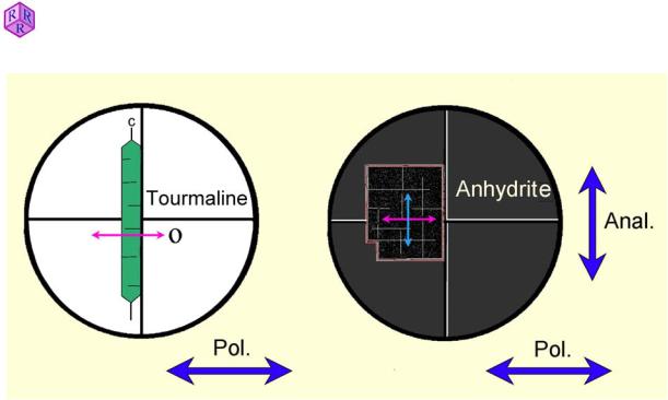
To align the polarization plane of the polarizer (= vibration direction of the pol-wave) with the E-W thread of the crosshairs, a grain mount of fine tourmaline needles can be used. First, a tourmaline needle is aligned with its c-axis parallel to the N-S direction of the crosshairs and then the polarizer rotated until the needle shows maximum absorption (Fig. 1.6-1, left part). For this procedure, the analyzer is kept out of the light path.
Explanation: Tourmaline is a strongly dichroic mineral (dichroism, Ch. 4). Maximum absorption occurs perpendicular to the c-axis, i.e. in the vibration direction of the O-wave. Caution! Ensure that the adjusted position of the polarizer is not changed afterwards. Mark the position on the holder, or fix it with an adhesive tape. Many microscopes have a mark on the adjustable polarizer which indicates where the aligned position should be.
Once the position of the polarizer has been properly oriented, the polarization plane of the analyzer is aligned into the N-S direction of the crosshairs. When inserting the analyzer into the light path, the field of view should appear black if the polarization direction of the analyzer is oriented parallel N-S. If the field of view is not black, the analyzer must be adjusted.
Alternatively, the proper orientation of the analyzer can be checked with a grain mount of small crystal fragments of anhydrite. For this purpose a perfect crystal fragment is chosen and positioned with its edges on the N-S and E-W threads of the crosshairs. The analyzer is inserted into the light path and, when properly oriented in N-S, the fragment will appear black (in extinction) (Fig. 1.6-1, right part). Should the crystal transmit light, the analyzer must be adjusted.
Explanation: When the anhydrite crystal is properly oriented with its edges matching the crosshairs, the E-W vibrating pol-waves pass the crystal without changing their vibration direction and thus are blocked by the N-S oriented analyzer (see also Ch. 4.2).
19
Raith, Raase, Reinhardt – January 2011
Guide to Thin Section Microscopy |
Microscope |
|
|
|
|
Figure 1.6-1: Adjustment of the polarizers
Rotatable analyzers allow to adjust the orientation of the polarisation filter with a graduated spindle that can be locked after adjustment. In the more common swing-in analyzers, the correct position of the polarizing filter in the mould must be adjusted manually. In many modern microscopes only one of the two polarizers can be adjusted while the orientation of either lower polarizer or analyzer is fixed.
If high-magnification objectives are used for observation (without any object in the light pass!) and the aperture diaphragm is open, the field of view does not appear completely black under crossed polarizers. This is caused by a rotation of the E-W vibrating pol-waves at the strongly curved surfaces of the objective lenses. Under conoscopic illumination an interference image is observed which resembles the centred optic-axis interference figure of a weakly birefringent positive uniaxial crystal (Ch. 5).
1.7 Trouble-shooting
1.7.1 Optimising the image of the specimen
It is assumed that the microscope has been aligned for Köhler illumination (Ch. 1.5).
(1)If the thin section can be perfectly focused with low magnification objectives (MO= 2.5 to 10), but remains out of focus when objectives of higher magnification (MO= 20, 40, 63 etc.) are used, it should be checked whether the thin section is lying on its wrong side, i.e. with the cover glass down (see free working distance of objectives, Table 1).
(2)If the correctly placed thin section cannot be focused with high-magnification objectives, the cover glass is too thick and must be replaced by a cover glass of the standard thickness of 0.17 mm.
20

Guide to Thin Section Microscopy |
Microscope |
(3)Proper focusing may also be hampered by dusty surfaces of the optical components. The dust is best removed with a soft and completely grease-free brush.
(4)Indistinct and blurred images result when the front lenses of objectives and oculars are smudged with fingerprints resp. the grease of the eyelashes. In such cases it is advised to breathe on the lenses and then carefully clean them with a lens tissue or Kleenex tissue. Oily stains (e.g. by immersion liquids) are best removed with a cotton bud dipped in aether or ethyl alcohol. Solvents, however, should be applied with caution as the lenses are mounted in synthetic resins. To avoid fingerprints on the front lenses, objectives should always be changed with the fingers on the revolving turret, not on the objectives.
1.7.2 Eliminating poor illumination
The microscope alignment for Köhler illumination ensures a perfect, evenly illuminated field of view (Ch. 1.5). However, problems may still be encountered with the quality of illumination.
If the field of view is unevenly or not at all illuminated, although the light source is working and the field diaphragm illuminated, potential causes of such problems in the substage assembly are:
(a)The front lens of the condenser or an extra lens below the condenser have not been properly put into or out of the optical pathway. As a result, the lens mounts may partially or completely block the light beam.
(b)Filters are not correctly positioned.
(c)When using low-magnification objectives for observation, the field of view will be poorly illuminated if either the field diaphragm is closed down, the condenser is in a high position, or the front lens of the condenser is in the light path.
The sub-stage illumination is perfectly adjusted if the thin section, when viewed sideways from the top, shows an evenly and brightly illuminated round field which can be enlarged or reduced in size by opening or closing the field diaphragm.
|
If the image of the thin section remains imperfect when viewed through the oculars, the |
|
|
causes for poor illumination must be sought in the tube part of the microscope. The light path |
|
|
may be partially or completely blocked if: |
|
2011 |
(a) The revolving nosepiece was not properly mounted on the microscope stand or an |
|
– January |
objective has not clicked into place after a change of magnification. |
|
(b) An accessory plate has not been fully inserted into the tube. |
||
Reinhardt |
(c) The analyzer has not been fully inserted (swung-in) or removed (swung-out). |
|
|
||
Raase, |
(d) The Amici-Bertrand lens has been partially swung-in (out). |
|
(e) An accessory magnification lens (e.g. Optovar of the Zeiss Photomicroscope) has not |
||
Raith, |
||
properly clicked into position. |
||
|
21

Guide to Thin Section Microscopy |
Microscope |
1.7.3 Sources of error in the crossed-polarizers mode
(a)In a thin section of standard thickness (25Pm) quartz and feldspar grains show first-order grey-white interference colours. If instead brownish-white shades are observed, the polarizers are not precisely adjusted, i.e. their polarizing planes are not oriented perpendicular to one another. Hence, polarizer and analyzer must be adjusted following the instructions given in Ch. 1.6.
(b)If the quartz and feldspars grains show blue-green and orange-red interference colours instead of the first-order grey-white colours, the first-order red plate (O-plate) resides in the light path (cf. accessory plates, Ch. 4.2.4).
(c)The crosshairs (or crossed micrometer) must be precisely oriented N-S and E-W. For this purpose the tube has two slots into which the notch on the ocular casing fits. These allow to fix the ocular with its crosshairs in the standard N-S–E-W orientation or, if needed, in a 45° diagonal orientation.
Raith, Raase, Reinhardt – January 2011
22

Raith, Raase, Reinhardt – January 2011
Guide to Thin Section Microscopy |
Measuring angles |
2. Measuring angles, lengths and thicknesses
2.1 Measurement of angles
The determination of an unknown mineral or the determination of the composition of a solid solution may require measuring an angle between two specific linear or planar features. Such features include crystal faces, cleavage planes, twin planes and vibration directions.
With the help of angles between cleavage sets, pyroxenes can be distinguished from amphiboles, for example. Of even greater importance is the determination of angles between mineral planes and optical vibration directions (Ch. 4.2.4).
Angles are determined using a polarized-light microscope with a 360° scale on the rotating stage. Furthermore, a reference direction is required which is provided by the crosshairs in the ocular. A prerequisite for a precise measurement is exact centring of the microscope and the use of a higher-magnification objective with a small depth of field. For the determination of angles between cleavage sets, the analyzer should be out of the light path.
Ideally the angle between cleavage planes, crystal faces etc. is measured on a grain or a grain domain where both planes are parallel to the viewing direction. If the thin section is defocused, whereby the aperture diaphragm is partially closed to obtain a sufficiently high contrast, fringes of equal brightness appear on both sides of the traces of such planes and migrate outwards in a symmetric fashion. Such an ideal grain orientation is rarely realised in thin section, though, and it is sufficient to find grains in which the traces of the cleavage planes appear as thin dark lines.
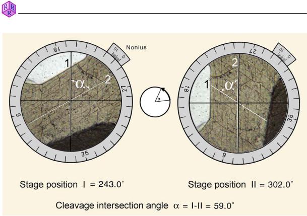
For measurement, the thin section is oriented, either by hand or using a mechanical stage, such that the intersection of the traces of the planes is in the centre of the crosshairs. By rotating the stage it can be tested whether the intersection remains centred. If it moves offcentre the objective will need to be centred. While rotating the stage avoid pressing against it unnecessarily.
Next, cleavage set 1 is rotated such that is lies parallel to the N-S thread of the crosshairs. Then, the angle I is read from the vernier at the stage edge (Fig. 2.1-1, left). Now the microscope stage is rotated until the cleavage set 2 is parallel to the N-S thread of the crosshairs, and angle II is read from the vernier. (Fig. 2.1-1, right). The difference between I and II is the angle in question.
Note: If the 360° mark is crossed during the procedure, the two partial angles have to be added up.
23
Raith, Raase, Reinhardt – January 2011
Guide to Thin Section Microscopy |
Measuring angles |
|
|
|
|
Figure 2.1-1: Measurement of the angle Į between two cleavage sets.
The following may contribute to measuring errors:
1.Mechanical tolerance of the stage
2.Precision in reading the scale on the stage
3.Precision in placing the traces of planes parallel to one of the crosshairs
4.Precision in finding the exact extinction position, if angles are measured towards vibration directions
5.Quality of the planar elements used and their traces in the mineral grain
Assuming careful positioning of the traces of the planes and care in reading the scale, the cause of the largest error commonly relates to a badly defined cleavage. Particularly minerals with cleavage classified as poor or merely distinct may show cleavage traces that are either not exactly planar, or stepped, or too short. Furthermore, the cleavage may be bent due to deformation or it may host secondary minerals. During preparation, holes may form as mineral fragments break out along cleavages, or careful grinding may lead to very few cleavage planes opening up and becoming visible. Twin planes may also not follow the ideal crystallographic directions exactly.
A common problem is to find a grain of ideal crystallographic orientation in a thin section (the intersection line between two sets of planes being exactly vertical), and this may indeed prove to be impossible in certain cases. When using a grain with a slightly inclined orientation an error of a few degrees must be taken into consideration.
24