

thin_section_microscopy
.pdfRaith, Raase, Reinhardt – January 2011
Guide to Thin Section Microscopy |
Crystal shape and symmetry |
Figure 3.1-7: Skeletal crystal shapes
A: Olivine (basalt); B, C, D: Diopside, ferriclinopyroxene and kirschsteinite (slags); E: Atoll garnet (gneiss); F: Quartz in microcline (graphic granite).
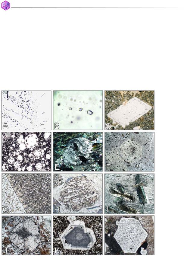
Figure 3.1-8: Spherulitic, dendritic and radiating crystals
A: Chlorite spherulites (charnockite); B: Spherules of radiating zeolite showing Brewster crosses (limburgite; +Pol); C: Spherules (obsidian, Lipari); D: Dendritic devitrification domains (basalt); E: Fan-shaped spherulitic devitrification (obsidian, Arran); F: Microlites with dendritic, fan-shaped devitrification domains (obsidian, Arran); G: Chalcedony (agate); H: Baryte rosettes with Brewster crosses; I: Anhydrite rosette (anhydrite,
Zechstein). |
35 |
|
Raith, Raase, Reinhardt – January 2011
Guide to Thin Section Microscopy |
Crystal shape and symmetry |
|
|
|
|
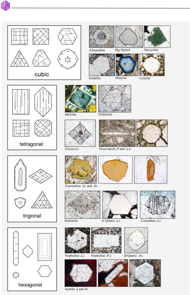
Figure 3.1-9: Sections of euhedral crystals
36

Raith, Raase, Reinhardt – January 2011
Guide to Thin Section Microscopy |
Crystal shape and symmetry |
|
|
|
|
Figure 3.1-9 contd.: Sections of euhedral crystals
37

Guide to Thin Section Microscopy |
Crystal shape and symmetry |
Raith, Raase, Reinhardt – January 2011
Figure 3.1-10: Relation between crystal form and cross-sections using the example of clinopyroxene (titanaugite). Plane-polarized light.
38
Raith, Raase, Reinhardt – January 2011
Guide to Thin Section Microscopy |
Cleavage and fracture |
3.2 Cleavage and fracture
Numerous minerals display cleavage. Mechanical force imposed on mineral grains, during a rock’s geological history or during thin section preparation, can generate crystallographically defined planar fractures (i.e., cleavage). Abundance and quality of cleavage are mineralspecific, but are also dependent on the level of stress to which minerals were exposed. Cleavage is an important morphological property for mineral identification and, at the same time, a criterion for the orientation of a mineral in thin section (Figs. 3.1-10, 3.2-1). For exact positioning of cleavages and measuring of cleavage angles see Ch. 2.1 and Fig. 2.1-1.
In mineral cross-sections under the microscope, cleavage is recognised as – in the ideal case – straight traces of planes dissecting the grain. If the cleavage planes are oriented parallel to the viewing direction they appear as thin dark lines. With increasing tilt the lines broaden and the traces appear increasingly blurry in the direction of tilting. If the cleavage orientation is at a small angle to thin section plane, cleavage traces may not be observed.
Many minerals only show poor cleavage or no cleavage at all. If exposed to external mechanical stress or internal stress during rapid cooling such mineral grains develop irregular fractures. These may still have a preferred orientation.
Cleavage and fracturing are dependent on grain size. Minerals forming small grains commonly show neither cleavage nor fracture.
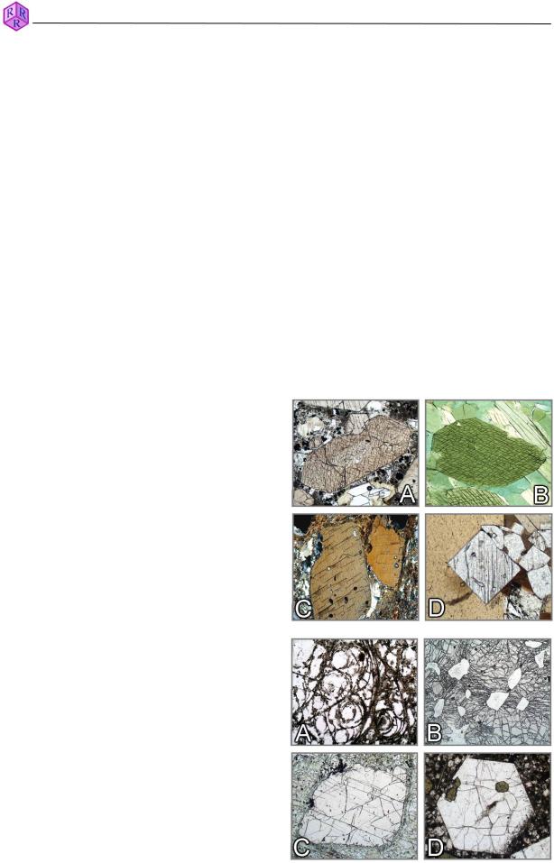
Figure 3.2-1: Cleavage
A.Augite: Section orthogonal to c axis. The {110} cleavage planes form angles of 87° and 93°.
B.Hornblende: Section orthogonal to c axis. The {110} cleavage planes form angles of 56° and 124°.
C.Kyanite: Two sections approximately orthogonal to c show the typical pattern of very good cleavage {100} and distinct cleavage {010}.
D.Sillimanite: The section orthogonal to c shows the good cleavage {100}.
Figure 3.2-2: Fracture
A.Perlite: Due to quenching of the glassy material (obsidian) concentrically curved tension cracks developed.
B.Pyrope: Radial cracks emanating from coesite inclusions now largely transformed to quartz. The cause of the fracturing is the volume increase from the coesite-quartz transformation, resulting in increased pressure imposed on the garnet host.
C.Garnet: Fracture planes oriented parallel to narrowspaced jointing in a basic granulite.
D.Nepheline: Irregular tension cracks caused by rapid cooling.
39
Guide to Thin Section Microscopy |
Twinning |
3.3. Twinning
Twins are generated through crystal-structure-controlled intergrowths of two or more individual crystal segments with a defined symmetrical relationship. Twinning can also result from deformation (as in calcite). The individual parts of a twinned mineral are intergrown such that they either mirror each other's orientation (the mirror plane being the twin plane), or they are rotated against each other by a specific angle (the rotation axis being the twin axis), or both. The twin interface commonly corresponds to the twin plane.
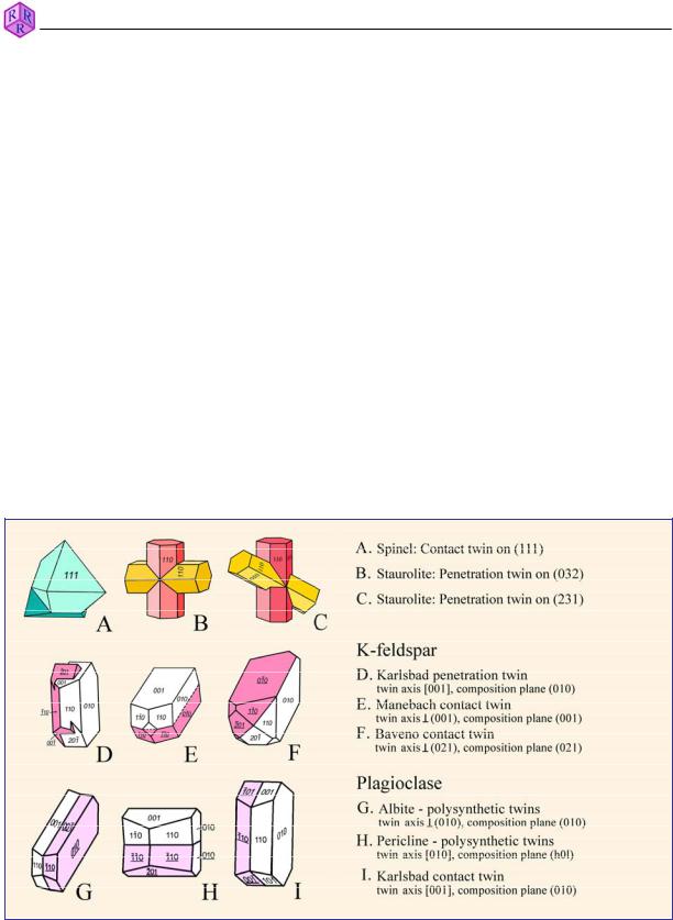
For many mineral species twinning is an important property for identification. There are different kinds of twinning such as contact twins, penetration twins, simple twins, multiple twins, polysynthetic (or lamellar) twins (Fig. 3.3-1).
In thin section, twinning is commonly easily recognised under crossed polarizers if the mineral is anisotropic. The individual parts of twinned crystals show different brightness and interference colour, and on turning the microscope stage different extinction positions are revealed. There are exceptions, however, as not all types of twins can be recognised under the microscope. If the indicatrix orientation of the individual parts of twinned crystals is identical, they are indistinguishable under crossed polarizers (e.g., the most abundant quartz twins have a twin axis parallel to c, which means the indicatrices are in parallel alignment; thus, the twins go into extinction simultaneously).
Raith, Raase, Reinhardt – January 2011
Figure 3.3-1: Types of twinning
40
Raith, Raase, Reinhardt – January 2011
Guide to Thin Section Microscopy |
Twinning |
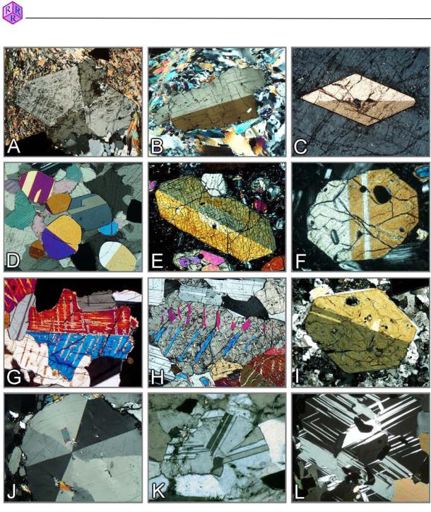
Figure 3.3-2A: Twinning in minerals
A. Staurolite, penetration twin on (320); B. Kyanite, simple twin on (100); C. Titanite, simple twin on (100); D. Simple and lamellar twins in chondrodite grains; E-G. Simple and lamellar twins on (100) in augite; H. Pigeonite twin on (100) inverted to orthopyroxene with augite exsolution lamellae on (001); I. Amphibole, simple twin on (100). J. Cordierite sector twinning (triplet); K. Cordierite triplet with lamellar twins; L. Lamellar twins in cordierite.
41

Raith, Raase, Reinhardt – January 2011
Guide to Thin Section Microscopy |
Twinning |
Figure 3.3-2B: Twinning in minerals
A. Chloritoid, lamellar twins on (001); B. Mg-rich chlorite (clinochlore), lamellar twins on (001); C. Cummingtonite, thin twin lamellae on (100); D. Plagioclase laths with polysynthetic, lamellar twins; E-G. Polysynthetic twinning in plagioclase; H. Sanidine, Carlsbad twins; I. K-feldpar, Baveno growth twin; J. Microcline with characteristic cross-hatched twinning (section approximately parallel to (001)); K. Microcline, twin set (section approximately parallel to (001)); Chessboard albite, formed by albitisation of microcline.
42

Guide to Thin Section Microscopy |
Twinning |
Figure 3.3-2C: Twinning in minerals
A-C. Leucite with complex lamellar twinning; D. Grossular (anomalous-birefringent) with concentric-oscillating zoning and sector twins; E. Uvarovite (anomalous-birefringent) with sector twins; F. Larnite with thin polysynthetic twins on (100) and (010); G-H. Calcite with polysynthetic glide twins on {0112}; I. Corundum with twin lamellae on {1011}.
Raith, Raase, Reinhardt – January 2011
43
Raith, Raase, Reinhardt – January 2011
Guide to Thin Section Microscopy |
Inclusions |
3.4 Inclusions, intergrowths, alteration products
Additional characteristics that can be used for mineral identification are, on the one hand, inclusions which have been incorporated during crystal growth (primary inclusions such as melt inclusions or matrix phases; Fig. 3.4-1), and, on the other hand, inclusions that formed from alteration of the host mineral (secondary inclusions, such as saussurite, sagenite; Fig. 3.4-5G,H and Fig. 3.4-2M-O). Secondary products also include regular intergrowths from unmixing (e.g., perthite and antiperthite in feldspars, exsolution lamellae in pyroxenes and amphiboles; Fig. 3.4-2) and multi-phase intergrowths from mineral reactions (e.g., symplectites, kelyphite, myrmekite; Fig. 3.4-3 and Fig. 3.4-4). Characteristic textures are also generated by pseudomorphic replacement of mineral phases caused by reactions involving a hydrous fluid (e.g., chloritisation of garnet, serpentinisation of olivine; Fig. 3.4-5).
Figure 3.4-1: Inclusions
A,B: Fluid inclusions in quartz; C: Melt inclusions in plagioclase; D: Melt inclusions in leucite; E: Albite porpyroblasts with sigmoidal inclusion trails defined by tiny graphite particles; F: Cordierite porphyroblast showing inclusion trails that are identical to matrix foliation; G: Staurolite poikiloblast; H: Skeletal garnet; I: Chloritoid with minute inclusions forming an hour-glass structure; J: Andalusite with fine-grained inclusions (chiastholite); K: Nosean (dark domains contain minute exsolved opaque phases and fluid inclusions); L: Apatite, clouded interior due to tiny fluid inclusions.
44