

- •FOREWORD
- •0.1 APPROVAL
- •0.2 RECORD OF REVISIONS
- •0.3 LIST OF EFFECTIVE PAGES
- •0.4 TABLE OF CONTENTS
- •1 GENERAL
- •1.1 INTRODUCTION
- •1.2 CERTIFICATION BASIS
- •1.3 WARNINGS, CAUTIONS AND NOTES
- •1.4 DIMENSIONS
- •1.5 DEFINITIONS AND ABBREVIATIONS
- •1.6 UNITS OF MEASUREMENT
- •1.6.1 CONVERSION FACTORS
- •1.6.2 CONVERSION CHART LITER / US GALLON
- •1.7 THREE-VIEW DRAWING
- •1.8 SOURCE DOCUMENTATION
- •1.8.1 ENGINE AND ENGINE INSTRUMENTS
- •1.8.2 PROPELLER
- •2 OPERATING LIMITATIONS
- •2.1 INTRODUCTION
- •2.2 AIRSPEED
- •2.3 AIRSPEED INDICATOR MARKINGS
- •2.4 POWER-PLANT LIMITATIONS
- •2.5 ENGINE INSTRUMENT MARKINGS
- •2.6 WARNING, CAUTION AND STATUS LIGHTS
- •2.7 MASS (WEIGHT)
- •2.8 CENTER OF GRAVITY
- •2.9 APPROVED MANEUVERS
- •2.10 MANEUVERING LOAD FACTORS
- •2.11 OPERATING ALTITUDE
- •2.12 FLIGHT CREW
- •2.13 KINDS OF OPERATION
- •2.14 FUEL
- •2.15 LIMITATION PLACARDS
- •2.16 OTHER LIMITATIONS
- •2.16.1 TEMPERATURE
- •2.16.2 BATTERY CHARGE
- •2.16.3 EMERGENCY SWITCH
- •2.16.4 DOOR LOCKING DEVICE
- •2.16.5 ELECTRONIC EQUIPMENT
- •2.16.6 SMOKING
- •2.16.7 USE OF THE SUN VISORS
- •3 EMERGENCY PROCEDURES
- •3.1 INTRODUCTION
- •3.1.1 GENERAL
- •3.1.2 CERTAIN AIRSPEEDS IN EMERGENCIES
- •3.2 INSTRUMENT INDICATIONS IN PROHIBITED (RED) RANGE
- •3.2.1 ENGINE TEMPERATURE
- •3.2.2 OIL TEMPERATURE
- •3.2.3 OIL PRESSURE
- •3.2.4 GEARBOX TEMPERATURE
- •3.2.5 L/R FUEL TEMPERATURE
- •3.2.6 FUEL PRESSURE
- •3.2.7 ALTERNATOR AMPS
- •3.2.8 ALTERNATOR FAIL
- •3.3 ENGINE PROBLEMS
- •3.3.1 ENGINE PROBLEMS ON GROUND
- •3.3.2 ENGINE PROBLEMS DURING TAKE-OFF
- •3.3.3 ENGINE TROUBLESHOOTING IN FLIGHT
- •3.3.4 ENGINE FAILURE IN FLIGHT
- •3.3.5 RESTARTING THE ENGINE IN FLIGHT
- •3.3.6 DEFECTIVE RPM REGULATING SYSTEM
- •3.3.7 FUEL TRANSFER PUMP FAILURE
- •3.4 FAILURES IN THE ELECTRICAL SYSTEM
- •3.4.1 COMPLETE FAILURE OF THE ELECTRICAL SYSTEM
- •3.4.2 HIGH CURRENT
- •3.4.3 STARTER MALFUNCTION
- •3.5 SMOKE AND FIRE
- •3.5.1 SMOKE AND FIRE ON GROUND
- •3.5.2 SMOKE AND FIRE DURING TAKE-OFF
- •3.5.3 SMOKE AND FIRE IN FLIGHT
- •3.6 GLIDING
- •3.7 EMERGENCY LANDINGS
- •3.7.1 EMERGENCY LANDING WITH ENGINE OFF
- •3.7.2 LANDING WITH A DEFECTIVE TIRE ON THE MAIN LANDING GEAR
- •3.7.3 LANDING WITH DEFECTIVE BRAKES
- •3.8 RECOVERY FROM AN UNINTENTIONAL SPIN
- •3.9 OTHER EMERGENCIES
- •3.9.1 ICING
- •3.9.2 SUSPICION OF CARBON MONOXIDE CONTAMINATION IN THE CABIN
- •3.9.3 UNLOCKED DOORS
- •4A NORMAL OPERATING PROCEDURES
- •4A.1 INTRODUCTION
- •4A.2 AIRSPEEDS FOR NORMAL OPERATING PROCEDURES
- •4A.3 FLIGHT CHARACTERISTICS
- •4A.4 DAILY CHECK
- •4A.5 CHECKLISTS FOR NORMAL OPERATING PROCEDURES
- •4A.5.1 PRE-FLIGHT INSPECTION
- •4A.5.2 BEFORE STARTING ENGINE
- •4A.5.3 STARTING ENGINE
- •4A.5.4 BEFORE TAXIING
- •4A.5.5 TAXIING
- •4A.5.6 BEFORE TAKE-OFF
- •4A.5.7 TAKE-OFF
- •4A.5.8 CLIMB
- •4A.5.9 CRUISE
- •4A.5.10 FUEL TRANSFER
- •4A.5.11 DESCENT
- •4A.5.12 APPROACH & LANDING
- •4A.5.13 GO-AROUND
- •4A.5.14 AFTER LANDING
- •4A.5.15 ENGINE SHUT-DOWN
- •4A.5.16 POST FLIGHT INSPECTION
- •4A.5.17 PARKING
- •4A.5.18 FLIGHT IN RAIN
- •4A.5.19 REFUELING
- •4A.5.20 FLIGHT AT HIGH ALTITUDE
- •4B ABNORMAL OPERATING PROCEDURES
- •4B.1 PRECAUTIONARY LANDING
- •4B.2 INSTRUMENT INDICATIONS OUTSIDE OF GREEN RANGE
- •4B.2.2 COOLANT TEMPERATURE
- •4B.2.3 OIL TEMPERATURE
- •4B.2.4 OIL PRESSURE
- •4B.2.5 GEARBOX TEMPERATURE
- •4B.2.6 FUEL TEMPERATURE
- •4B.2.7 VOLTAGE
- •4B.2.8 CURRENT
- •4B.3 CAUTION-ALERTS
- •4B.3.1 ECU A FAILURE
- •4B.3.2 ECU B FAILURE
- •4B.3.3 FUEL QUANTITY LOW
- •4B.3.4 COOLANT LEVEL
- •4B.3.5 PITOT HEATING FAILURE
- •4B.3.6 ENGINE CAUTION (IF WHITE WIRE ANNUNCIATOR PANEL IS INSTALLED)
- •4B.4 CANOPY IN COOLING GAP POSITION
- •4B.5 FAILURES IN FLAP OPERATING SYSTEM
- •4B.6 LIGHTNING STRIKE
- •4B.7 LANDING WITH HIGH LANDING MASS
- •5 PERFORMANCE
- •5.1 INTRODUCTION
- •5.2 USE OF THE PERFORMANCE TABLES AND DIAGRAMS
- •5.3 PERFORMANCE TABLES AND DIAGRAMS
- •5.3.1 AIRSPEED CALIBRATION
- •5.3.2 FUEL FLOW DIAGRAM
- •5.3.3 PRESSURE ALTITUDE - DENSITY ALTITUDE
- •5.3.4 INTERNATIONAL STANDARD ATMOSPHERE
- •5.3.5 STALLING SPEEDS
- •5.3.6 WIND COMPONENTS
- •5.3.7 TAKE-OFF DISTANCE
- •5.3.8 CLIMB PERFORMANCE - TAKE-OFF CLIMB
- •5.3.9 CLIMB PERFORMANCE - CRUISE CLIMB
- •5.3.10 CRUISING (TRUE AIRSPEED TAS)
- •5.3.11 LANDING DISTANCE - FLAPS LDG
- •5.3.12 LANDING DISTANCE - ABNORMAL FLAP POSITION
- •5.3.13 GRADIENT OF CLIMB ON GO-AROUND
- •5.3.14 GLIDE
- •5.3.15 APPROVED NOISE DATA
- •6 MASS AND BALANCE / EQUIPMENT LIST
- •6.1 INTRODUCTION
- •6.2 DATUM PLANE
- •6.3 MASS AND BALANCE REPORT
- •6.4 FLIGHT MASS AND CENTER OF GRAVITY
- •6.4.1 MOMENT ARMS
- •6.4.2 LOADING DIAGRAM
- •6.4.3 CALCULATION OF LOADING CONDITION
- •6.4.4 PERMISSIBLE CENTER OF GRAVITY RANGE
- •6.4.5 PERMISSIBLE MOMENT RANGE
- •6.5 EQUIPMENT LIST AND EQUIPMENT INVENTORY
- •7.1 INTRODUCTION
- •7.2 AIRFRAME
- •7.3 FLIGHT CONTROLS
- •7.4 INSTRUMENT PANEL
- •7.5 LANDING GEAR
- •7.6 SEATS AND SAFETY HARNESSES
- •7.7 BAGGAGE COMPARTMENT
- •7.8 CANOPY, REAR DOOR, AND CABIN INTERIOR
- •7.9 POWER PLANT
- •7.9.1 ENGINE, GENERAL
- •7.9.2 OPERATING CONTROLS
- •7.9.3 PROPELLER
- •7.9.4 FUEL SYSTEM
- •7.9.5 COOLING SYSTEM
- •7.9.6 TURBO CHARGER SYSTEM
- •7.9.7 OIL SYSTEMS
- •7.10 ELECTRICAL SYSTEM
- •7.10.1 GENERAL
- •7.10.2 ENGINE CONTROL UNIT / ECU
- •7.11 PITOT-STATIC SYSTEM
- •7.12 STALL WARNING SYSTEM
- •8 AIRPLANE HANDLING, CARE AND MAINTENANCE
- •8.1 INTRODUCTION
- •8.2 AIRPLANE INSPECTION INTERVALS
- •8.3 AIRPLANE ALTERATIONS OR REPAIRS
- •8.4 GROUND HANDLING / ROAD TRANSPORT
- •8.4.1 GROUND HANDLING WITHOUT TOW BAR
- •8.4.2 GROUND HANDLING WITH TOW BAR
- •8.4.3 PARKING
- •8.4.4 MOORING
- •8.4.5 JACKING
- •8.4.6 ALIGNMENT
- •8.4.7 ROAD TRANSPORT
- •8.5 CLEANING AND CARE
- •8.5.1 PAINTED SURFACES
- •8.5.2 CANOPY AND REAR DOOR
- •8.5.3 PROPELLER
- •8.5.4 ENGINE
- •8.5.5 INTERIOR SURFACES
- •8.6 GROUND DE-ICING
- •9 SUPPLEMENTS
- •9.1 INTRODUCTION
- •9.2 LIST OF SUPPLEMENTS
DA 40 NG AFM
Airplane
Description
7.10 ELECTRICAL SYSTEM
Electrical System Schematic
Doc. # 6.01.15-E |
Rev. 1 |
15-Mar-2011 |
Page 7 - 37 |
|
|
|
|

Airplane
DA 40 NG AFM
Description
7.10.1 GENERAL
The DA 40 NG has a 28 Volt DC system, which can be sub-divided into:
-Power generation
-Storage
-Distribution
-Consumers
Power Generation
Power generation is provided by a 70 Ampère alternator (generator) which is mounted on the bottom left side of the engine. The alternator is driven by a flat-belt.
The power output line of the alternator is connected to the ENG ECU bus via a 100 A fuse, which is installed in the instrument panel. The power output line also runs through the current sensor, which provides an indication of the power being supplied to the electrical system by the alternator including the current for battery charging.
In the event of a main battery failure the field of the alternator is energized by two 12 V, 7.2 Ah sealed-lead-acid batteries (ECU backup batteries) which are installed behind the first ring frame. The ENGINE MASTER switch connects the ECU backup battery to the alternator voltage regulator via a 10 A fuse.
Alternator Control:
The alternator control unit includes a comprehensive set of diagnostic functions that will
'warn the operator using a warning message (ALTN FAIL on the G1000 system (if installed)
'or ALTERNATOR on the White Wire annunciator panel (if installed)) in case of overor undervoltage as well as a couple of other internal warning levels.
Page 7 - 38 |
Rev. 1 |
15-Mar-2011 |
|
Doc. # 6.01.15-E |
|
|
|
|
|

DA 40 NG AFM
Airplane
Description
Storage
Main battery power is stored in a 24 V, 13.6 Ah lead-acid battery mounted behind the baggage compartment frame. The main battery is connected to the battery bus via the battery-relay which is installed in the relay junction box behind the baggage compartment frame.
The battery relay is controlled with the ELECTRIC MASTER key switch which is located in the center of the instrument panel.
In addition, two 12 V, 7.2 Ah sealed-lead-acid batteries (ECU backup-batteries) are installed behind the first ring frame as a further source of electrical power for the Engine
Control Unit (ECU B only).
Under normal operating conditions the ECU backup batteries are charged by the ECU bus. In the event of an alternator failure and a depleted main battery the ECU backup batteries automatically supply electrical power to ECU B via a 32 A fuse. This prevents the engine from stopping in the unlikely event of an alternator failure and a totally discharged main battery.
In addition, a non-rechargeable dry battery is installed in the IFR model as a further source of power for the attitude gyro (artificial horizon) and the flood light. When the EMERGENCY switch is set to ON, these two systems are supplied with power for 1 hour, independent of all other electrical consumers. During each 100 hour inspection, this battery is checked for proper functioning. Every 2 years or after use (broken seal on the switch) the battery pack must be replaced.
Doc. # 6.01.15-E |
Rev. 1 |
15-Mar-2011 |
Page 7 - 39 |
|
|
|
|

Airplane
DA 40 NG AFM
Description
Distribution
Electrical power is distributed via the hot battery bus, the battery bus 1, the battery bus 2, the ECU-bus, the main bus, the essential bus and the avionic bus.
Hot Battery Bus:
The hot battery bus is directly connected to the main-battery installed in the relay junction box and cannot be disconnected from the main battery. The hot battery bus provides power to the accessory power plug and ELT which are protected by their own fuses.
Battery Bus 1:
The battery bus 1 is connected to the main-battery via the battery-relay which can be controlled by the ELECTRIC MASTER key switch. The battery bus 1 provides power to the battery bus 2 and heavy duty power to the starter.
The battery bus 1 is also connected to the power input line of the external power plug.
Battery Bus 2:
The battery bus 2 is connected to the battery bus 1 via a 100 A fuse and provides power to the ECU bus via a 80 A fuse. It also provides power to the main bus via the power relay which can be controlled by the ELECTRIC MASTER key switch and the ESSENTIAL BUS switch. The ELECTRIC MASTER key switch must be set to ON and the ESSENTIAL BUS switch must be set to OFF to connect the battery bus to the main bus.
ECU Bus:
The ECU bus is connected to the battery bus 2 via a 80 A fuse and provides power for the ECU A and ECU B and their fuel pumps. It is also connected to the power output line of the alternator via a 100 A fuse. It also provides power for charging the ECU backupbattery. The ENGINE MASTER switch must be set to ON to activate the ECU A and ECU B to the ECU bus.
Page 7 - 40 |
Rev. 1 |
15-Mar-2011 |
|
Doc. # 6.01.15-E |
|
|
|
|
|

DA 40 NG AFM
Airplane
Description
Main Bus:
The main bus is connected to the battery bus via the power-relay. It provides power to the consumers directly connected to the main bus and the avionic bus via the avionic master-relay. The AVIONIC MASTER switch must be set to ON to connect the main bus to the avionic bus. Under normal operating conditions the main bus is also connected to the essential bus via the essential tie-relay. In the event of an alternator failure the pilot must switch ON the ESSENTIAL BUS switch (refer to Section 3.4 - FAILURES IN THE ELECTRICAL SYSTEM). This separates the main bus from the battery bus and the essential bus and the equipment connected to the main bus no longer has power.
Essential Bus:
Under normal operating conditions the essential bus is connected to the main bus via the essential tie-relay. The essential bus provides power to the consumers connected to the essential bus. The AVIONIC MASTER switch must be set to ON to connect the essential bus to the avionic bus. In the event of an alternator failure the pilot must switch ON the ESSENTIAL BUS switch (refer to Section 3.4 - FAILURES OF THE ELECTRICAL
SYSTEM). This separates the essential bus from the main bus. The essential bus is then connected to the battery bus 2 which provides battery power for a limited time to the equipment essential for safe flight and landing.
Consumers
The individual consumers (e.g. radio, electrical fuel transfer pump, position lights, etc.) are connected to the appropriate bus via automatic circuit breakers.
Designations and abbreviations used to identify the circuit breakers are explained in Section 1.5 - DEFINITIONS AND ABBREVIATIONS.
Doc. # 6.01.15-E |
Rev. 1 |
15-Mar-2011 |
Page 7 - 41 |
|
|
|
|

Airplane
DA 40 NG AFM
Description
Voltmeter
The voltmeter shows the voltage of the essential bus. Under normal operating conditions the alternator voltage is shown, otherwise it is the voltage of the main battery.
Ammeter
The ammeter displays the intensity of current which is supplied to the electrical system by the alternator, including the current for battery charging.
Landing and Taxi Lights
Landing and taxi lights are built into the left wing, and are each operated by means of a switch (LANDING, TAXI) on the row of switches on the instrument panel.
Position and Strobe Lights
Combined position and strobe lights (anti collision lights) are installed on both wing tips. Each system is operated by a switch (POSITION, STROBE) on the row of switches on the instrument panel.
Flood Light
A two-dimensional light emitter is mounted above the instrument panel. It illuminates the instrument panel as well as all levers, switches, etc. With a rotary button (FLOOD) in the left-hand section of the instrument panel the flood light is switched on and its brightness is adjusted.
Page 7 - 42 |
Rev. 1 |
15-Mar-2011 |
|
Doc. # 6.01.15-E |
|
|
|
|
|
DA 40 NG AFM
Airplane
Description
Instrument Lighting
With a rotary button (INSTRUMENT) in the left-hand section of the instrument panel the internal lighting of the instruments is switched on and its brightness is adjusted.
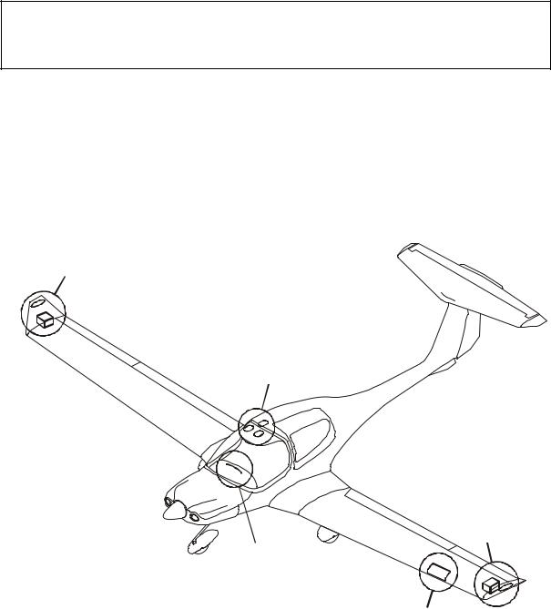
Right Wing Tip
Light Assy
Reading Lights (3 off)
Left Wing Tip
Light Assy
Instrument Panel
Flood Light Strip
Landing/Taxi
Light Assy
Doc. # 6.01.15-E |
Rev. 1 |
15-Mar-2011 |
Page 7 - 43 |
|
|
|
|

Airplane
DA 40 NG AFM
Description
Pitot Heating
The Pitot probe, which provides measurement for the Pitot-static system, is electrically heated. The heating is activated with a switch (PITOT) on the row of switches on the instrument panel. The temperature is automatically kept constant by means of a thermal switch on the Pitot probe, and as an additional safety measure a thermal fuse is built in.
If this thermal fuse is activated, the Pitot heating can no longer be switched on. PITOT FAIL
'on the G1000 (if installed) or PITOT on the White Wire annunciator panel (if installed) will be displayed, if the thermal fuse or the thermal switch is activated and the PITOT HT
'is set to ON. The PITOT HT OFF indication on the G1000 (if installed) is on if the Pitot heating is switched off.
Page 7 - 44 |
Rev. 1 |
15-Mar-2011 |
|
Doc. # 6.01.15-E |
|
|
|
|
|