

SECTION 11:ABNORMAL
OPERATION
11.1 REVERSIONARY MODE
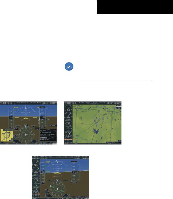
Shouldasystemdetectedfailureoccurineitherdisplay, the G1000 automatically enters reversionary mode. In reversionary mode, critical flight instrumentation is combined with engine instrumentation on the remaining display. Minimal navigation capability is available on the reversionary mode display.
Normal PFD Display
SECTION 11 – ABNORMAL
OPERATION
Reversionary display mode can also be manually activated by the pilot if the system fails to detect a display problem. The reversionary mode is activated manually by pressing the red DISPLAY BACKUP button on the bottom of the audio panel (GMA 1347). Pressing the red DISPLAYBACKUPbuttonagaindeactivatesreversionary mode.
NOTE: The Cessna Pilot’s Operating Handbook (POH) always takes precedence over the information found in this section.
Normal MFD Display
MFD in Reversionary Mode
Figure 11-1 G1000 Reversionary Mode: Failed PFD
Garmin G1000 Cockpit Reference Guide for the Cessna Nav III |
11-1 |

SECTION 11 – ABNORMAL
OPERATION
11.2 ABNORMAL COM OPERATION
When a COM tuning failure is detected by the system, the emergency frequency (121.500 MHz) is automatically loaded into the active frequency field of the COM radio for which the tuning failure was detected. In the event of a dual display failure, the emergency frequency (121.500 MHz) automatically becomes the active frequency to the pilot through the pilot headset.
11.3 UNUSUAL ATTITUDES
The PFD will ‘declutter’ when the aircraft enters an unusual attitude. Only the primary functions will be displayed in these situations.
The following information is removed from the PFD (and corresponding softkeys are disabled) when the aircraft experiences unusual attitudes:
• |
Traffic Annunciations |
– |
Timer/References |
• |
AFCS Annunciations |
– |
Nearest Airports |
• |
Flight director Com- |
– |
Flight Plan |
|
mand Bars |
– |
Messages |
• |
Inset Map |
– |
Procedures |
• |
Temperatures |
– |
DME Tuning |
• |
DME Information |
• |
Barometric Minimum |
|
Window |
|
Descent Altitude Box |
• |
Wind Data |
• |
Glideslope, Glidepath, |
• |
Selected Heading Box |
|
and Vertical Deviation |
• |
Selected Course Box |
|
Indicators |
• |
Transponder Status |
• |
Altimeter Barometric |
|
Box |
|
Setting |
• |
System Time |
• |
Selected Altitude |
• |
PFD Setup Menu |
• |
VNV Target Altitude |
•Windows displayed in the lower right corner of the PFD:
Red extreme pitch warning chevrons pointing toward the horizon are displayed starting at 50 degrees above and 30 degrees below the horizon line.
Figure 11-2 Extreme Pitch Indication
11.4STORMSCOPE OPERATION WITH LOSS OF HEADING INPUT
If heading is lost, strikes and/or cells must be cleared manually after the execution of each turn. This is to ensure that the strike and/or cell positions are depicted accurately in relation to the nose of the aircraft.
11.5HAZARD DISPLAYS WITH LOSS OF GPS POSITION
If GPS position is lost, or becomes invalid, selected hazards being displayed on the Navigation Map Page will be removed until GPS position is again established. The icons in the lower right of the screen, indicating the selected functions for display, will show an ‘X’, as shown in Figure 11-3.
Figure 11-3 Loss of Hazard Functions with Loss of GPS Position
11-2 |
Garmin G1000 Cockpit Reference Guide for the Cessna Nav III |
11.6 DEAD RECKONING
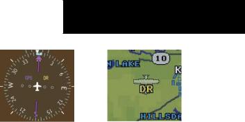
IfatanytimetheG1000detectsaninvalidGPSsolution or is unable to calculate a GPS position, the system will automaticallyreverttoDeadReckoning(DR)mode. InDR mode, the G1000 uses its last-known position combined with continuously updated airspeed and heading data (when available) to calculate and display the aircraft’s current estimated position.
DR mode is indicated on the G1000 by the appearance of the letters ‘DR’ superimposed in yellow over the ‘own aircraft’symbolasshowninFigure11-4. Inaddition,‘DR’ will be prominently displayed, also in yellow, on the HSI slightlyaboveandtotherightoftheaircraftsymbolonthe CDI as shown in Figure 11-4. Lastly, but at the same time, a ‘GPS NAV LOST’ alert message will appear on the PFD.
Normal navigation using GPS/WAAS source data will resume automatically once a valid GPS solution is restored.
It is important to note that estimated navigation data supplied by the G1000 in DR mode may become increasingly unreliable and must not be used as a sole means of navigation. If while in DR mode airspeed and/or heading data is also lost or not available, the DR function may not be capable of accurately tracking your estimated position and, consequently, the system may display a path that is different than the actual movement of the aircraft. Estimated position information displayed by the G1000 through DR while there is no heading and/or airspeed data available should not for navigation.
DR mode is inherently less accurate than the standard GPS/WAAS mode due to the lack of satellite measurements needed to determine a position. Changes in wind speed and/or wind direction will compound the relative inaccuracy of DR mode. Because of this degraded accuracy,thecrewmustmaintainpositionawarenessusing other navigation equipment until GPS-derived position data is restored.
SECTION 11 – ABNORMAL
OPERATION
CDI ‘DR’ Indication on PFD |
Symbolic Aircraft |
|
(Map pages and Inset Map) |
Figure 11-4 Dead Reckoning Indications
As a result of operating in DR mode, all GPS-derived data will be computed based upon an estimated position and will be displayed as yellow text on the map to denote degraded navigation source information. This data includes the following:
•NavigationStatusBoxfieldsexceptActiveLeg,TAS, and DTK
•GPS Bearing Pointer
•Wind data and pointers in the Wind Data Box on the PFD
•Track Bug
•All Bearing Pointer Distances
•Active Flight Plan distances, bearings, and ETE values
Also,whiletheG1000isinDRmode,theautopilotwill not couple to GPS, and both TAWS and Terrain Proximity will be disabled. Additionally, the accuracy of all nearest information (airports, airspaces, and waypoints) will be questionable. Finally, airspace alerts will continue to function, but with degraded accuracy.
Garmin G1000 Cockpit Reference Guide for the Cessna Nav III |
11-3 |

SECTION 11 – ABNORMAL
OPERATION
Blank Page
11-4 |
Garmin G1000 Cockpit Reference Guide for the Cessna Nav III |
SECTION 12:ANNUNCIATIONS &
ALERTS
NOTE: The Cessna aircraft Pilot’s Operating Handbook (POH) supersedes information found in this document.
The G1000 Alerting System conveys alerts to the pilot using a combination of the following items:
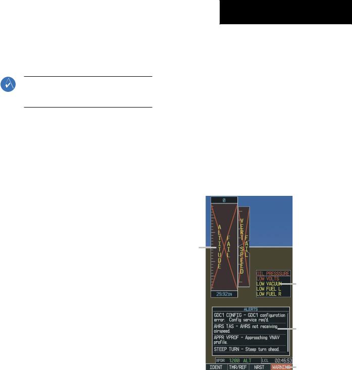
•Annunciation Window: The Annunciation Windowdisplaysabbreviatedannunciationtext. Text color is based on alert levels described later in the Alert Levels Definitions section. The Annunciation Window is located to the right of the Altitude and Vertical Speed boxes on the display. All Cessna Nav III annunciations can be displayed simultaneously in the Annunciation Window. A white horizontal line separates annunciations that are acknowledged from annunciations that are not yet acknowledged. Higher priority annunciations are displayed towards thetopofthewindow. Lowerpriorityannunciations are displayed towards the bottom of the window.
•Alerts Window: The Alerts Window displays alert text messages. Up to 64 prioritized alert messages can be displayed in the Alerts Window. Pressing the ALERTS Softkey displays the Alerts Window. PressingtheALERTSSoftkeyasecondtimeremoves theAlertsWindowfromthedisplay. WhentheAlerts Windowisdisplayed,thepilotcanusethelargeFMS Knob to scroll through the alert message list.
•Softkey Annunciation: During certain alerts, the ALERTS Softkey may appear as a flashing annunciation to accompany an alert. The ALERTS Softkey assumes a new label consistent with the alert level (WARNING, CAUTION, or ADVISORY).
SECTION 12 – ANNUNCIATIONS
& ALERTS
By pressing the softkey annunciation, the pilot acknowledges awareness of the alert. The softkey then returns to the previous ALERTSlabel. If alerts are still present, the ALERTSlabel will be displayed ininversevideo(whitebackgroundwithblacktext). The pilot can press the ALERTS Softkey a second time to view alert text messages.
•System Annunciations: Typically, a large red ‘X’ appearsinwindowswhenafailureisdetectedinthe LRU providing the information to the window. See the G1000 System Annunciations section for more information.
•Audio Alerting System: The G1000 system issues audioalerttoneswhenspecificsystemconditionsare met. SeetheAlertLevelsDefinitionssectionformore information.
System
Annunciation
Red ‘X’
Annunciation
Window
Alerts Window
ALERTS Softkey
Figure 12-1 G1000 Alerting System Annunciation
Garmin G1000 Cockpit Reference Guide for the Cessna Nav III |
12-1 |