

SECTION 6 – AUTOMATIC
FLIGHT CONTROL
If the Selected Altitude is reached |
during CWS |
maneuvering, the Altitude Reference is |
not changed. |
To adjust the Altitude Reference in this case, the CWS |
|
Button must be pressed again after the Selected Altitude |
|
is reached.
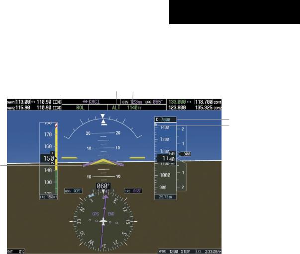
Altitude Hold |
Flight Director Alti- |
Mode Active |
tude Reference |
Selected Altitude
Selected Altitude Bug
Command Bars Hold
Pitch Attitude to Main-
tain Altitude Reference
Figure 6-7 Altitude Hold Mode
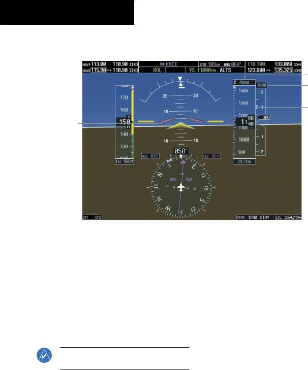
Vertical Speed Mode (VS)
In Vertical Speed Mode, the flight director acquires and maintains a Vertical Speed Reference. Current aircraft vertical speed (to the nearest 100 fpm) becomes the Vertical Speed Reference at the moment of Vertical Speed Mode activation. Vertical Speed Mode does not consider the relative position of the Selected Altitude in relation to the current aircraft altitude at the time of mode activation, so it is possible to use Vertical Speed Mode while not climbing/descending to the Selected Altitude.
Vertical Speed Mode is activated by pressing the VS Key; the ‘VS’ annunciation appears in the AFCS Status Box to indicate the active pitch mode, along with the Vertical SpeedReferencetotheright. TheVerticalSpeedReference is also displayed above the Vertical Speed Indicator. A VerticalSpeedReferenceBugcorrespondingtotheVertical Speed Reference is shown on the indicator.
Garmin G1000 Cockpit Reference Guide for the Cessna Nav III |
6-7 |
SECTION 6 – AUTOMATIC
FLIGHT CONTROL
Vertical Speed |
|
Vertical |
Selected Altitude Capture |
||
|
Speed |
||||
Mode Active |
|
Reference |
|
Mode Armed |
|
|
|
||||
|
|
|
|
|
|
Selected Altitude
Vertical Speed
Reference
Vertical Speed
Reference Bug
Command Bars Indicate Climb to Attain Vertical Speed
Figure 6-8 Vertical Speed Mode
Changing the Vertical Speed Reference
The Vertical Speed Reference (shown both in the AFCS Status Box and above/below the Vertical Speed Indicator) may be changed by:
•Using the NOSE UP/NOSE DN Keys
•By pressing the CWS Button, hand-flying the aircraft to attain a new Vertical Speed Reference, then releasing the CWS Button
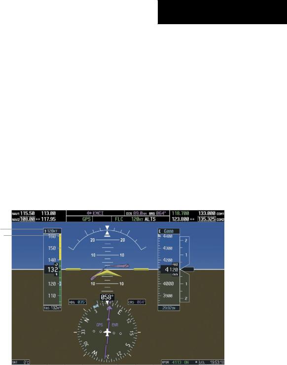
Flight Level Change Mode (FLC)
NOTE:The SelectedAltitude should be set before selecting Flight Level Change Mode.
Flight Level Change Mode is selected by pressing the FLC Key. When Flight Level Change Mode is active, the flight director continuously monitors Selected Altitude, airspeed, and altitude. This mode acquires and maintains the Airspeed Reference while climbing or descending to the Selected Altitude (shown above the Altimeter). The Airspeed Reference is set to the current airspeed upon mode activation. Flight Level Change Mode is indicated by an ‘FLC’ annunciation beside the Airspeed Reference in the AFCS Status Box. The Airspeed Reference is also displayed directly above the Airspeed Indicator, along with a bug corresponding to the Airspeed Reference along the tape.
Engine power must be adjusted to allow the autopilot to fly the aircraft at a pitch attitude corresponding to the Airspeed Reference and the desired flight profile (climb or
6-8 |
Garmin G1000 Cockpit Reference Guide for the Cessna Nav III |
SECTION 6 – AUTOMATIC
FLIGHT CONTROL
descent). Theflightdirectormaintainsthecurrentaltitude until either engine power or the Airspeed Reference are adjusted and does not allow the aircraft to climb or descend away from the Selected Altitude.
Changing the Airspeed Reference
The Airspeed Reference (shown in both the AFCS Status Box and above the Airspeed Indicator) may be adjusted:
•Using the NOSE UP/NOSE DN Keys
•BypressingtheCWSButton,hand-flyingtheaircraft to a new airspeed, then releasing the CWS Button to establish the new Airspeed Reference
Flight Level Change |
|
Airspeed |
Altitude Hold |
|
Mode Active |
|
Reference |
Mode Armed |
|
|
||||
|
|
|
|
|
Airspeed Reference
Airspeed Reference Bug
Figure 6-9 Flight Level Change Mode
Garmin G1000 Cockpit Reference Guide for the Cessna Nav III |
6-9 |
SECTION 6 – AUTOMATIC
FLIGHT CONTROL
Vertical Navigation Modes (VPTH, ALTV)
NOTE: Pressing the CWS Button while Vertical Path Tracking Mode is active does not cancel the mode. The autopilot guides the aircraft back to the descent path upon release of the CWS Button.
NOTE: VNAV flight director pitch modes are available only in conjunction with GPS roll modes.
When a vertical profile (VNAV flight plan) is active and the VNV Key is pressed, Vertical Path Tracking Mode is armedinpreparationfordescentpathcapture. ‘VPTH’(or ‘/V’ when Glidepath or Glideslope Mode is concurrently armed) is annunciated in white in addition to previously armed modes. If applicable, the appropriate altitude capture mode is armed for capture of the next VNAV Target Altitude (ALTV) or the Selected Altitude (ALTS), whichever is greater.
NOTE: The Selected Altitude takes precedence over any other vertical constraints.
Vertical Navigation (VNAV) flight control is available for enroute/terminal cruise and descent operations when VNAV has been enabled and a VNAV flight plan (with at least one vertical waypoint) or vertical direct-to has been activated. Refer to the GPS Navigation Section for more informationonVNAVflightplans. Theflightdirectormay be armed for VNAV at any time, but no target altitudes are captured during a climb.
The Command Bars provide vertical profile guidance based on specified altitudes (entered manually or loaded from the database) at waypoints in the active flight plan or vertical direct-to. The appropriate VNAV flight control modes are sequenced by the flight director to follow the path defined by the vertical profile. Upon reaching the last waypoint in the VNAV flight plan, the flight director transitions to Altitude Hold Mode and cancels any armed VNAV modes.
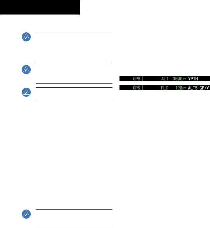
Vertical Path Tracking Mode (VPTH)
NOTE:If another pitch mode key is pressed while Vertical Path Tracking Mode is selected, Vertical Path Tracking Mode reverts to armed.
Figure 6-10 Vertical Path Tracking Armed Annunciations
Priortodescentpathinterception,theSelectedAltitude must be set below the current aircraft altitude by at least 75 ft. For the flight director to transition from Altitude Hold to Vertical Path Tracking Mode, acknowledgment is required within five minutes of descent path capture by:
•Pressing the VNV Key
•Adjusting the Selected Altitude
Ifacknowledgmentisnotreceivedwithinoneminuteof descent path interception, the white ‘VPTH’ annunciation andtheVNVKeyannunciatorlightstarttoflash. Flashing continues until acknowledged or the descent path is intercepted. If the descent is not confirmed by the time of interception, Vertical Path Tracking Mode remains armed and the descent is not captured.
6-10 |
Garmin G1000 Cockpit Reference Guide for the Cessna Nav III |
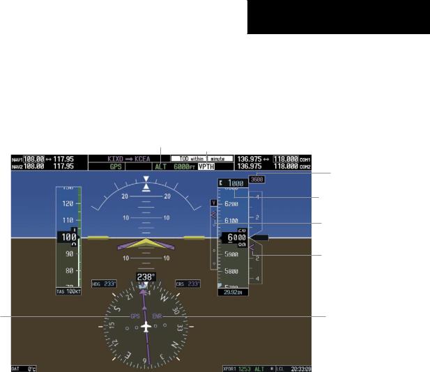
Inconjunctionwiththe“TOD[topofdescent]within1 minute” annunciation in the Navigation Data Box, VNAV indications (VNAV Target Altitude, vertical deviation, and vertical speed required) appear on the PFDs in magenta (Figure 6-11).
Altitude Hold Mode Active
HSI Set to GPS
SECTION 6 – AUTOMATIC
FLIGHT CONTROL
Vertical Path Tracking Armed, (Flashing Indicates Acknowledgment Required)
VNAV Target
Altitude
Selected Altitude Below
VNAV Target
Vertical Deviation
Indicator
Required Vertical
Speed Bug
Enroute Phase of
Flight
Figure 6-11 Vertical Path Capture
Garmin G1000 Cockpit Reference Guide for the Cessna Nav III |
6-11 |
SECTION 6 – AUTOMATIC
FLIGHT CONTROL
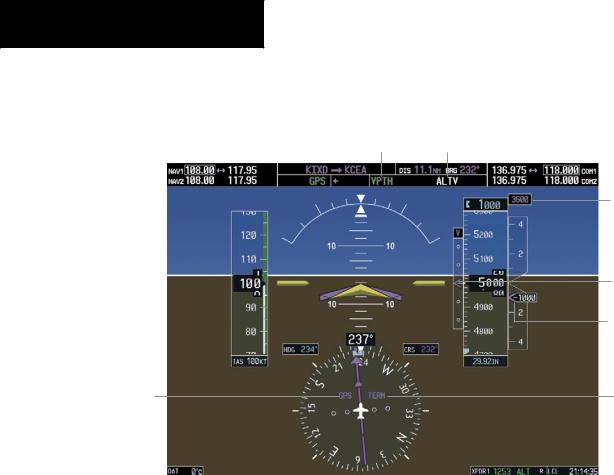
When a descent leg is captured (Figure 6-12), Vertical |
|
Path Tracking becomes active and tracks the descent pro- |
|
file. An altitude capture mode (‘ALTS’ or ‘ALTV’) is armed |
|
as appropriate. |
|
Vertical Path Tracking Active |
VNAV Target Altitude Capture Armed |
VNAV
Target
Altitude
Vertical
Deviation
Indicator
Required
Vertical
Speed Bug
Terminal
HSI Set to GPS Phase of
Flight
Figure 6-12 Vertical Path Tracking Mode
Automatic Pitch Hold Reversion
Several situations can occur while Vertical Path Tracking Mode is active which cause the flight director to revert to Pitch Hold Mode. Vertical Path Tracking and the appropriate altitude capture modes are armed for possible descent profile recapture if the vertical deviation:
•Exceeds 200 ft during an overspeed condition
•Experiencesadiscontinuityexceeding200ftdueto a flight plan change
•Becomes invalid due to excessive cross-track error, track angle error
•Cannot be computed for a leg type (such as a hold or procedure turn)
The following circumstances cause mode reversion without arming Vertical Path Tracking Mode:
•Navigation source manually changed from GPS
•CNCL VNV Softkey selected on the Active Flight Plan Page (MFD)
•All remaining vertical waypoints deleted from the flight plan
•Displays entering Reversionary Mode
Non-Path Descents
Pitch Hold, Vertical Speed, and Flight Level Change modes can also be used to fly non-path descents while
6-12 |
Garmin G1000 Cockpit Reference Guide for the Cessna Nav III |
VNAV flight control is selected. If the VS or FLC Key is pressed while Vertical Path Tracking Mode is selected, Vertical Path Tracking Mode reverts to armed along with the appropriate altitude capture mode to allow profile recapture.
Figure 6-13 Flight Level Change VNAV Non-Path Descent
To prevent immediate profile re-capture, the following must be satisfied:
•Atleasttensecondshavepassedsincethenon-path transition was initiated
•Verticaldeviationfromtheprofilehasexceeded250 ft, but is now less than 200 ft
Pressing the VNV Key twice re-arms Vertical Path Tracking for immediate profile re-capture.
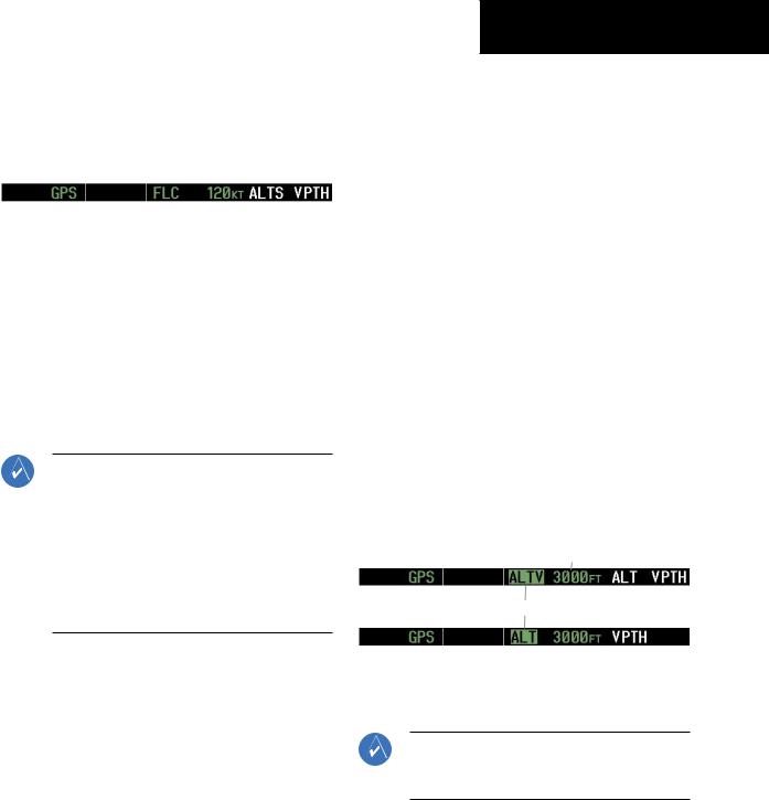
VNAV Target Altitude Capture Mode (ALTV)
NOTE: ArmedVNAVTargetAltitude and Selected Altitude capture modes are mutually exclusive. However, Selected Altitude Capture Mode is armed implicitly (not annunciated) whenever VNAV Target Altitude Capture Mode is armed. This ensures the SelectedAltitude is not violated during a change from VNAV Target Altitude Capture to SelectedAltitude Capture Mode close to Selected Altitude interception.
VNAV Target Altitude Capture is analogous to Selected Altitude Capture Mode and is armed automatically after the VNV Key is pressed and the next VNAV Target Altitude is to be intercepted before the Selected Altitude. The annunciation ‘ALTV’ indicates that the VNAV Target Altitude is to be captured. VNAV Target Altitudes are shown in the active flight plan or vertical direct-to, and canbeenteredmanuallyorloadedfromadatabase(seethe GPS Navigation Section for details). At the same time as “TOD within 1 minute” is annunciated in the Navigation
SECTION 6 – AUTOMATIC
FLIGHT CONTROL
Data Box, the VNAV Target Altitude is displayed above the Vertical Speed Indicator (see Figure 6-12). VNAV Target Altitudes can be modified until VNAV Target Altitude Capture Mode becomes active.
As the aircraft nears the VNAV Target Altitude, the flight director automatically transitions to VNAV Target Altitude Capture Mode with Altitude Hold Mode armed. This automatic transition is indicated by the green ‘ALTV’ annunciation flashing for up to ten seconds and the appearance of the white ‘ALT” annunciation. The VNAV Target Altitude is shown as the Altitude Reference beside the ‘ALTV’ annunciation.
At 50 ft from the VNAV Target Altitude, the flight director automatically transitions from VNAV Target Altitude Capture to Altitude Hold Mode and tracks the level leg. As Altitude Hold Mode becomes active, the white ‘ALT’ annunciation moves to the active pitch mode field and flashes green for ten seconds to indicate the automatic transition. The flight director automatically arms Vertical Path Tracking, allowing upcoming descent legs to be captured and subsequently tracked.
Altitude Reference (In This
Case, Equal To VNAV
Altitude Target)
Flash up to 10 sec, Indicating Automatic Transition
Figure 6-14 VNAV Altitude Capture
Changing the VNAV Target Altitude
NOTE: Pressing the CWS Button while in VNAV Target Altitude Capture Mode does not cancel the mode.
Garmin G1000 Cockpit Reference Guide for the Cessna Nav III |
6-13 |