

- •Chapter 1
- •1.1 Motivation
- •1.2 Objective of the Specification
- •1.3 Scope of the Document
- •1.4 Document Organization
- •Chapter 2
- •Chapter 3
- •3.1 Goals for the Universal Serial Bus
- •3.2 Taxonomy of Application Space
- •3.3 Feature List
- •Chapter 4
- •4.1 USB System Description
- •4.1.1 Bus Topology
- •4.2 Physical Interface
- •4.2.1 Electrical
- •4.2.2 Mechanical
- •4.3 Power
- •4.3.1 Power Distribution
- •4.3.2 Power Management
- •4.4 Bus Protocol
- •4.5 Robustness
- •4.5.1 Error Detection
- •4.5.2 Error Handling
- •4.6 System Configuration
- •4.6.1 Attachment of USB Devices
- •4.6.2 Removal of USB Devices
- •4.6.3 Bus Enumeration
- •4.7 Data Flow Types
- •4.7.1 Control Transfers
- •4.7.2 Bulk Transfers
- •4.7.3 Interrupt Transfers
- •4.7.4 Isochronous Transfers
- •4.7.5 Allocating USB Bandwidth
- •4.8 USB Devices
- •4.8.1 Device Characterizations
- •4.8.2 Device Descriptions
- •4.9 USB Host: Hardware and Software
- •4.10 Architectural Extensions
- •Chapter 5
- •5.1 Implementer Viewpoints
- •5.2 Bus Topology
- •5.2.1 USB Host
- •5.2.2 USB Devices
- •5.2.3 Physical Bus Topology
- •5.2.4 Logical Bus Topology
- •5.2.5 Client Software-to-function Relationship
- •5.3 USB Communication Flow
- •5.3.1 Device Endpoints
- •5.3.2 Pipes
- •5.4 Transfer Types
- •5.5 Control Transfers
- •5.5.1 Control Transfer Data Format
- •5.5.2 Control Transfer Direction
- •5.5.3 Control Transfer Packet Size Constraints
- •5.5.4 Control Transfer Bus Access Constraints
- •5.5.5 Control Transfer Data Sequences
- •5.6 Isochronous Transfers
- •5.6.1 Isochronous Transfer Data Format
- •5.6.2 Isochronous Transfer Direction
- •5.6.3 Isochronous Transfer Packet Size Constraints
- •5.6.4 Isochronous Transfer Bus Access Constraints
- •5.6.5 Isochronous Transfer Data Sequences
- •5.7 Interrupt Transfers
- •5.7.1 Interrupt Transfer Data Format
- •5.7.2 Interrupt Transfer Direction
- •5.7.3 Interrupt Transfer Packet Size Constraints
- •5.7.4 Interrupt Transfer Bus Access Constraints
- •5.7.5 Interrupt Transfer Data Sequences
- •5.8 Bulk Transfers
- •5.8.1 Bulk Transfer Data Format
- •5.8.2 Bulk Transfer Direction
- •5.8.3 Bulk Transfer Packet Size Constraints
- •5.8.4 Bulk Transfer Bus Access Constraints
- •5.8.5 Bulk Transfer Data Sequences
- •5.9 Bus Access for Transfers
- •5.9.1 Transfer Management
- •5.9.2 Transaction Tracking
- •5.9.3 Calculating Bus Transaction Times
- •5.9.4 Calculating Buffer Sizes in Functions and Software
- •5.9.5 Bus Bandwidth Reclamation
- •5.10 Special Considerations for Isochronous Transfers
- •5.10.1 Example Non-USB Isochronous Application
- •5.10.2 USB Clock Model
- •5.10.3 Clock Synchronization
- •5.10.4 Isochronous Devices
- •5.10.5 Data Prebuffering
- •5.10.6 SOF Tracking
- •5.10.7 Error Handling
- •5.10.8 Buffering for Rate Matching
- •Chapter 6
- •6.1 Architectural Overview
- •6.3 Cable
- •6.4 Cable Assembly
- •6.4.1 Detachable Cable Assemblies
- •6.4.3 Low-speed Captive Cable Assemblies
- •6.4.4 Prohibited Cable Assemblies
- •6.5.1 USB Icon Location
- •6.5.2 USB Connector Termination Data
- •6.5.3 Series “A” and Series “B” Receptacles
- •6.5.4 Series “A” and Series “B” Plugs
- •6.6.1 Description
- •6.6.2 Construction
- •6.6.3 Electrical Characteristics
- •6.6.4 Cable Environmental Characteristics
- •6.6.5 Listing
- •6.7 Electrical, Mechanical and Environmental Compliance Standards
- •6.7.1 Applicable Documents
- •6.8 USB Grounding
- •Chapter 7
- •7.1 Signaling
- •7.1.1 USB Driver Characteristics
- •7.1.2 Data Signal Rise and Fall
- •7.1.3 Cable Skew
- •7.1.4 Receiver Characteristics
- •7.1.5 Device Speed Identification
- •7.1.6 Input Characteristics
- •7.1.7 Signaling Levels
- •7.1.8 Data Encoding/Decoding
- •7.1.9 Bit Stuffing
- •7.1.10 Sync Pattern
- •7.1.11 Data Signaling Rate
- •7.1.12 Frame Interval and Frame Interval Adjustment
- •7.1.13 Data Source Signaling
- •7.1.14 Hub Signaling Timings
- •7.1.15 Receiver Data Jitter
- •7.1.16 Cable Delay
- •7.1.17 Cable Attenuation
- •7.1.18 Bus Turn-around Time and Inter-packet Delay
- •7.1.19 Maximum End-to-end Signal Delay
- •7.2 Power Distribution
- •7.2.1 Classes of Devices
- •7.2.2 Voltage Drop Budget
- •7.2.3 Power Control During Suspend/Resume
- •7.2.4 Dynamic Attach and Detach
- •7.3 Physical Layer
- •7.3.1 Regulatory Requirements
- •7.3.2 Bus Timing/Electrical Characteristics
- •7.3.3 Timing Waveforms
- •Chapter 8
- •8.1 Bit Ordering
- •8.2 SYNC Field
- •8.3 Packet Field Formats
- •8.3.1 Packet Identifier Field
- •8.3.2 Address Fields
- •8.3.3 Frame Number Field
- •8.3.4 Data Field
- •8.3.5 Cyclic Redundancy Checks
- •8.4 Packet Formats
- •8.4.1 Token Packets
- •8.4.2 Start-of-Frame Packets
- •8.4.3 Data Packets
- •8.4.4 Handshake Packets
- •8.4.5 Handshake Responses
- •8.5 Transaction Formats
- •8.5.1 Bulk Transactions
- •8.5.2 Control Transfers
- •8.5.3 Interrupt Transactions
- •8.5.4 Isochronous Transactions
- •8.6 Data Toggle Synchronization and Retry
- •8.6.1 Initialization via SETUP Token
- •8.6.2 Successful Data Transactions
- •8.6.3 Data Corrupted or Not Accepted
- •8.6.4 Corrupted ACK Handshake
- •8.6.5 Low-speed Transactions
- •8.7 Error Detection and Recovery
- •8.7.1 Packet Error Categories
- •8.7.2 Bus Turn-around Timing
- •8.7.3 False EOPs
- •8.7.4 Babble and Loss of Activity Recovery
- •Chapter 9
- •9.1 USB Device States
- •9.1.1 Visible Device States
- •9.1.2 Bus Enumeration
- •9.2 Generic USB Device Operations
- •9.2.1 Dynamic Attachment and Removal
- •9.2.2 Address Assignment
- •9.2.3 Configuration
- •9.2.4 Data Transfer
- •9.2.5 Power Management
- •9.2.6 Request Processing
- •9.2.7 Request Error
- •9.3 USB Device Requests
- •9.3.1 bmRequestType
- •9.3.2 bRequest
- •9.3.3 wValue
- •9.3.4 wIndex
- •9.3.5 wLength
- •9.4 Standard Device Requests
- •9.4.1 Clear Feature
- •9.4.2 Get Configuration
- •9.4.3 Get Descriptor
- •9.4.4 Get Interface
- •9.4.5 Get Status
- •9.4.6 Set Address
- •9.4.7 Set Configuration
- •9.4.8 Set Descriptor
- •9.4.9 Set Feature
- •9.4.10 Set Interface
- •9.4.11 Synch Frame
- •9.5 Descriptors
- •9.6 Standard USB Descriptor Definitions
- •9.6.1 Device
- •9.6.2 Configuration
- •9.6.3 Interface
- •9.6.4 Endpoint
- •9.6.5 String
- •9.7 Device Class Definitions
- •9.7.1 Descriptors
- •9.7.2 Interface(s) and Endpoint Usage
- •9.7.3 Requests
- •Chapter 10
- •10.1 Overview of the USB Host
- •10.1.1 Overview
- •10.1.2 Control Mechanisms
- •10.1.3 Data Flow
- •10.1.4 Collecting Status and Activity Statistics
- •10.1.5 Electrical Interface Considerations
- •10.2 Host Controller Requirements
- •10.2.1 State Handling
- •10.2.2 Serializer/Deserializer
- •10.2.3 Frame Generation
- •10.2.4 Data Processing
- •10.2.5 Protocol Engine
- •10.2.6 Transmission Error Handling
- •10.2.7 Remote Wakeup
- •10.2.8 Root Hub
- •10.2.9 Host System Interface
- •10.3 Overview of Software Mechanisms
- •10.3.1 Device Configuration
- •10.3.2 Resource Management
- •10.3.3 Data Transfers
- •10.3.4 Common Data Definitions
- •10.4 Host Controller Driver
- •10.5 Universal Serial Bus Driver
- •10.5.1 USBD Overview
- •10.5.2 USBD Command Mechanism Requirements
- •10.5.3 USBD Pipe Mechanisms
- •10.5.4 Managing the USB via the USBD Mechanisms
- •10.5.5 Passing USB Preboot Control to the Operating System
- •10.6 Operating System Environment Guides
- •Chapter 11
- •11.1 Overview
- •11.1.1 Hub Architecture
- •11.1.2 Hub Connectivity
- •11.2 Hub Frame Timer
- •11.2.1 Frame Timer Synchronization
- •11.2.2 EOF1 and EOF2 Timing Points
- •11.3 Host Behavior at End-of-Frame
- •11.3.1 Latest Host Packet
- •11.3.2 Packet Nullification
- •11.3.3 Transaction Completion Prediction
- •11.4 Internal Port
- •11.4.1 Inactive
- •11.4.2 Suspend Delay
- •11.4.3 Full Suspend (Fsus)
- •11.4.4 Generate Resume (GResume)
- •11.5 Downstream Ports
- •11.5.1 Downstream Port State Descriptions
- •11.6 Upstream Port
- •11.6.1 Receiver
- •11.6.2 Transmitter
- •11.7 Hub Repeater
- •11.7.1 Wait for Start of Packet from Upstream Port (WFSOPFU)
- •11.7.2 Wait for End of Packet from Upstream Port (WFEOPFU)
- •11.7.3 Wait for Start of Packet (WFSOP)
- •11.7.4 Wait for End of Packet (WFEOP)
- •11.8 Bus State Evaluation
- •11.8.1 Port Error
- •11.8.2 Speed Detection
- •11.8.3 Collision
- •11.9 Suspend and Resume
- •11.10 Hub Reset Behavior
- •11.10.1 Hub Receiving Reset on Upstream Port
- •11.11 Hub Port Power Control
- •11.11.1 Multiple Gangs
- •11.12 Hub I/O Buffer Requirements
- •11.12.1 Pull-up and Pull-down Resistors
- •11.12.2 Edge Rate Control
- •11.13 Hub Controller
- •11.13.1 Endpoint Organization
- •11.13.2 Hub Information Architecture and Operation
- •11.13.3 Port Change Information Processing
- •11.13.4 Hub and Port Status Change Bitmap
- •11.13.5 Over-current Reporting and Recovery
- •11.14 Hub Configuration
- •11.15 Descriptors
- •11.15.1 Standard Descriptors
- •11.15.2 Class-specific Descriptors
- •11.16 Requests
- •11.16.1 Standard Requests
- •11.16.2 Class-specific Requests
- •Index
Universal Serial Bus Specification Revision 1.1
11.7 Hub Repeater
The Hub Repeater provides the following functions:
Sets up and tears down connectivity on packet boundaries
Ensures orderly entry into and out of the Suspend state, including proper handling of remote wakeups
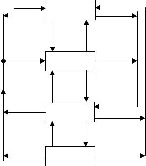
The state machine in Figure 11-9 shows the states and transitions needed to implement the Hub Repeater. Table 11-6 defines the Hub Repeater signals and events. The following sections describe the states and the transitions.
Several of the state transitions below will occur when an EOP is detected. When such a transition is indicated, the transition does not occur until after the hub has repeated the SE0-to-'J' transition and has driven 'J' for at least one bit time (bit time is determined by the speed of the port.)
Some of the transitions are triggered by an SOP. Transitions of this type occur as soon as the hub detects the 'J'-to-'K' transition, ensuring that the initial edge of the SYNC field is preserved.
Rx_Bus_Reset |
|
|
|
WFSOPFU |
|
State Machine Exports: |
|
|
|
Rptr_WFEOP(WFEOP) |
|
SOP_FU |
UEOP & !Lock |
Rptr_WFSOPFU(WFSOPFU) |
|
|
Rptr_Enter_WFEOPFU |
||
|
|
||
|
|
Rptr_Exit_WFEOPFU |
|
Rx_Resume |
|
|
|
WFEOPFU |
|
|
|
SOP_FU |
UEOP & Lock |
# = Logical OR |
|
|
|
||
|
Rx_Suspend |
& = Logical AND |
|
|
! = Logical NOT |
||
WFSOP |
EOF1 |
||
|
|||
DEOP |
SOP_FD |
|
|
WFEOP |
EOF2 |
|
|
|
|
||
Figure 11-9. Hub Repeater State Machine |
|||
249
Universal Serial Bus Specification Revision 1.1
Table 11-6. Hub Repeater Signal/Event Definitions
Signal/Event |
Event/Signal |
Description |
Name |
Source |
|
|
|
|
Rx_Bus_Reset |
Receiver |
Receiver is in the Bus_Reset state |
|
|
|
UEOP |
Internal |
EOP received from the upstream port |
|
|
|
DEOP |
Internal |
Generated when the Transmitter enters the SendJ state |
|
|
|
EOF1 |
Frame Timer |
Frame timer is at the EOF1 point or between EOF1 and End-of- |
|
|
Frame |
|
|
|
EOF2 |
Frame Timer |
Frame timer is at the EOF2 point or between EOF2 and End-of- |
|
|
Frame |
|
|
|
Lock |
Frame Timer |
Frame timer is locked |
|
|
|
Rx_Suspend |
Receiver |
Receiver is in the Suspend state |
|
|
|
Rx_Resume |
Receiver |
Receiver is in the Resume state |
|
|
|
SOP_FD |
Internal |
SOP received from downstream port or Hub Controller. |
|
|
Generated on the transition from the Idle to K state on a port. |
|
|
|
SOP_FU |
Internal |
SOP received from upstream port. Generated on the transition |
|
|
from the Idle to K state on the upstream port. |
|
|
|
11.7.1 Wait for Start of Packet from Upstream Port (WFSOPFU)
This state is entered in either of the following situations:
From any other state when the upstream Receiver is in the Bus_Reset state
From the WFSOP state if the frame timer is at or has passed the EOF1 point
From the WFEOP state at the EOF2 point.
From the WFEOPFU if the frame timer is not synchronized (locked) when an EOP is received on the upstream port.
In this state, the hub is waiting for an SOP on the upstream port and transitions on downstream ports are ignored by the Hub Repeater. While the Hub Repeater is in this state, connectivity is not established.
This state is used during the End-of-Frame (past the EOF1 point) to ensure that the hub will be able to receive the SOF when it is sent by the host.
11.7.2 Wait for End of Packet from Upstream Port (WFEOPFU)
The hub enters this state if the hub is in the WFSOP or WFSOPFU state and an SOP is detected on the upstream port. The hub also enters this state from the WFSOP, WFSOPFU, or WFEOP states when the Receiver enters the Resume state.
While in this state, connectivity is established from the upstream port to all enabled downstream ports. Downstream ports that are in the Enabled state are placed in the Transmit state on the transition to this state.
250