

- •Chapter 1
- •1.1 Motivation
- •1.2 Objective of the Specification
- •1.3 Scope of the Document
- •1.4 Document Organization
- •Chapter 2
- •Chapter 3
- •3.1 Goals for the Universal Serial Bus
- •3.2 Taxonomy of Application Space
- •3.3 Feature List
- •Chapter 4
- •4.1 USB System Description
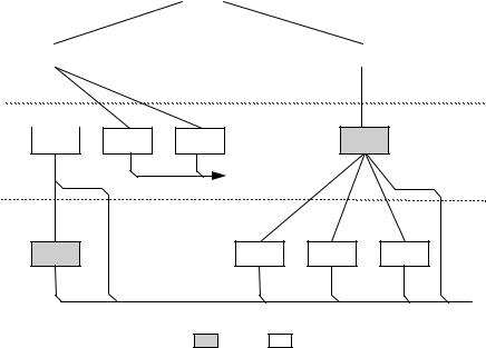
- •4.1.1 Bus Topology
- •4.2 Physical Interface
- •4.2.1 Electrical
- •4.2.2 Mechanical
- •4.3 Power
- •4.3.1 Power Distribution
- •4.3.2 Power Management
- •4.4 Bus Protocol
- •4.5 Robustness
- •4.5.1 Error Detection
- •4.5.2 Error Handling
- •4.6 System Configuration
- •4.6.1 Attachment of USB Devices
- •4.6.2 Removal of USB Devices
- •4.6.3 Bus Enumeration
- •4.7 Data Flow Types
- •4.7.1 Control Transfers
- •4.7.2 Bulk Transfers
- •4.7.3 Interrupt Transfers
- •4.7.4 Isochronous Transfers
- •4.7.5 Allocating USB Bandwidth
- •4.8 USB Devices
- •4.8.1 Device Characterizations
- •4.8.2 Device Descriptions
- •4.9 USB Host: Hardware and Software
- •4.10 Architectural Extensions
- •Chapter 5
- •5.1 Implementer Viewpoints
- •5.2 Bus Topology
- •5.2.1 USB Host
- •5.2.2 USB Devices
- •5.2.3 Physical Bus Topology
- •5.2.4 Logical Bus Topology
- •5.2.5 Client Software-to-function Relationship
- •5.3 USB Communication Flow
- •5.3.1 Device Endpoints
- •5.3.2 Pipes
- •5.4 Transfer Types
- •5.5 Control Transfers
- •5.5.1 Control Transfer Data Format
- •5.5.2 Control Transfer Direction
- •5.5.3 Control Transfer Packet Size Constraints
- •5.5.4 Control Transfer Bus Access Constraints
- •5.5.5 Control Transfer Data Sequences
- •5.6 Isochronous Transfers
- •5.6.1 Isochronous Transfer Data Format
- •5.6.2 Isochronous Transfer Direction
- •5.6.3 Isochronous Transfer Packet Size Constraints
- •5.6.4 Isochronous Transfer Bus Access Constraints
- •5.6.5 Isochronous Transfer Data Sequences
- •5.7 Interrupt Transfers
- •5.7.1 Interrupt Transfer Data Format
- •5.7.2 Interrupt Transfer Direction
- •5.7.3 Interrupt Transfer Packet Size Constraints
- •5.7.4 Interrupt Transfer Bus Access Constraints
- •5.7.5 Interrupt Transfer Data Sequences
- •5.8 Bulk Transfers
- •5.8.1 Bulk Transfer Data Format
- •5.8.2 Bulk Transfer Direction
- •5.8.3 Bulk Transfer Packet Size Constraints
- •5.8.4 Bulk Transfer Bus Access Constraints
- •5.8.5 Bulk Transfer Data Sequences
- •5.9 Bus Access for Transfers
- •5.9.1 Transfer Management
- •5.9.2 Transaction Tracking
- •5.9.3 Calculating Bus Transaction Times
- •5.9.4 Calculating Buffer Sizes in Functions and Software
- •5.9.5 Bus Bandwidth Reclamation
- •5.10 Special Considerations for Isochronous Transfers
- •5.10.1 Example Non-USB Isochronous Application
- •5.10.2 USB Clock Model
- •5.10.3 Clock Synchronization
- •5.10.4 Isochronous Devices
- •5.10.5 Data Prebuffering
- •5.10.6 SOF Tracking
- •5.10.7 Error Handling
- •5.10.8 Buffering for Rate Matching
- •Chapter 6
- •6.1 Architectural Overview
- •6.3 Cable
- •6.4 Cable Assembly
- •6.4.1 Detachable Cable Assemblies
- •6.4.3 Low-speed Captive Cable Assemblies
- •6.4.4 Prohibited Cable Assemblies
- •6.5.1 USB Icon Location
- •6.5.2 USB Connector Termination Data
- •6.5.3 Series “A” and Series “B” Receptacles
- •6.5.4 Series “A” and Series “B” Plugs
- •6.6.1 Description
- •6.6.2 Construction
- •6.6.3 Electrical Characteristics
- •6.6.4 Cable Environmental Characteristics
- •6.6.5 Listing
- •6.7 Electrical, Mechanical and Environmental Compliance Standards
- •6.7.1 Applicable Documents
- •6.8 USB Grounding
- •Chapter 7
- •7.1 Signaling
- •7.1.1 USB Driver Characteristics
- •7.1.2 Data Signal Rise and Fall
- •7.1.3 Cable Skew
- •7.1.4 Receiver Characteristics
- •7.1.5 Device Speed Identification
- •7.1.6 Input Characteristics
- •7.1.7 Signaling Levels
- •7.1.8 Data Encoding/Decoding
- •7.1.9 Bit Stuffing
- •7.1.10 Sync Pattern
- •7.1.11 Data Signaling Rate
- •7.1.12 Frame Interval and Frame Interval Adjustment
- •7.1.13 Data Source Signaling
- •7.1.14 Hub Signaling Timings
- •7.1.15 Receiver Data Jitter
- •7.1.16 Cable Delay
- •7.1.17 Cable Attenuation
- •7.1.18 Bus Turn-around Time and Inter-packet Delay
- •7.1.19 Maximum End-to-end Signal Delay
- •7.2 Power Distribution
- •7.2.1 Classes of Devices
- •7.2.2 Voltage Drop Budget
- •7.2.3 Power Control During Suspend/Resume
- •7.2.4 Dynamic Attach and Detach
- •7.3 Physical Layer
- •7.3.1 Regulatory Requirements
- •7.3.2 Bus Timing/Electrical Characteristics
- •7.3.3 Timing Waveforms
- •Chapter 8
- •8.1 Bit Ordering
- •8.2 SYNC Field
- •8.3 Packet Field Formats
- •8.3.1 Packet Identifier Field
- •8.3.2 Address Fields
- •8.3.3 Frame Number Field
- •8.3.4 Data Field
- •8.3.5 Cyclic Redundancy Checks
- •8.4 Packet Formats
- •8.4.1 Token Packets
- •8.4.2 Start-of-Frame Packets
- •8.4.3 Data Packets
- •8.4.4 Handshake Packets
- •8.4.5 Handshake Responses
- •8.5 Transaction Formats
- •8.5.1 Bulk Transactions
- •8.5.2 Control Transfers
- •8.5.3 Interrupt Transactions
- •8.5.4 Isochronous Transactions
- •8.6 Data Toggle Synchronization and Retry
- •8.6.1 Initialization via SETUP Token
- •8.6.2 Successful Data Transactions
- •8.6.3 Data Corrupted or Not Accepted
- •8.6.4 Corrupted ACK Handshake
- •8.6.5 Low-speed Transactions
- •8.7 Error Detection and Recovery
- •8.7.1 Packet Error Categories
- •8.7.2 Bus Turn-around Timing
- •8.7.3 False EOPs
- •8.7.4 Babble and Loss of Activity Recovery
- •Chapter 9
- •9.1 USB Device States
- •9.1.1 Visible Device States
- •9.1.2 Bus Enumeration
- •9.2 Generic USB Device Operations
- •9.2.1 Dynamic Attachment and Removal
- •9.2.2 Address Assignment
- •9.2.3 Configuration
- •9.2.4 Data Transfer
- •9.2.5 Power Management
- •9.2.6 Request Processing
- •9.2.7 Request Error
- •9.3 USB Device Requests
- •9.3.1 bmRequestType
- •9.3.2 bRequest
- •9.3.3 wValue
- •9.3.4 wIndex
- •9.3.5 wLength
- •9.4 Standard Device Requests
- •9.4.1 Clear Feature
- •9.4.2 Get Configuration
- •9.4.3 Get Descriptor
- •9.4.4 Get Interface
- •9.4.5 Get Status
- •9.4.6 Set Address
- •9.4.7 Set Configuration
- •9.4.8 Set Descriptor
- •9.4.9 Set Feature
- •9.4.10 Set Interface
- •9.4.11 Synch Frame
- •9.5 Descriptors
- •9.6 Standard USB Descriptor Definitions
- •9.6.1 Device
- •9.6.2 Configuration
- •9.6.3 Interface
- •9.6.4 Endpoint
- •9.6.5 String
- •9.7 Device Class Definitions
- •9.7.1 Descriptors
- •9.7.2 Interface(s) and Endpoint Usage
- •9.7.3 Requests
- •Chapter 10
- •10.1 Overview of the USB Host
- •10.1.1 Overview
- •10.1.2 Control Mechanisms
- •10.1.3 Data Flow
- •10.1.4 Collecting Status and Activity Statistics
- •10.1.5 Electrical Interface Considerations
- •10.2 Host Controller Requirements
- •10.2.1 State Handling
- •10.2.2 Serializer/Deserializer
- •10.2.3 Frame Generation
- •10.2.4 Data Processing
- •10.2.5 Protocol Engine
- •10.2.6 Transmission Error Handling
- •10.2.7 Remote Wakeup
- •10.2.8 Root Hub
- •10.2.9 Host System Interface
- •10.3 Overview of Software Mechanisms
- •10.3.1 Device Configuration
- •10.3.2 Resource Management
- •10.3.3 Data Transfers
- •10.3.4 Common Data Definitions
- •10.4 Host Controller Driver
- •10.5 Universal Serial Bus Driver
- •10.5.1 USBD Overview
- •10.5.2 USBD Command Mechanism Requirements
- •10.5.3 USBD Pipe Mechanisms
- •10.5.4 Managing the USB via the USBD Mechanisms
- •10.5.5 Passing USB Preboot Control to the Operating System
- •10.6 Operating System Environment Guides
- •Chapter 11
- •11.1 Overview
- •11.1.1 Hub Architecture
- •11.1.2 Hub Connectivity
- •11.2 Hub Frame Timer
- •11.2.1 Frame Timer Synchronization
- •11.2.2 EOF1 and EOF2 Timing Points
- •11.3 Host Behavior at End-of-Frame
- •11.3.1 Latest Host Packet
- •11.3.2 Packet Nullification
- •11.3.3 Transaction Completion Prediction
- •11.4 Internal Port
- •11.4.1 Inactive
- •11.4.2 Suspend Delay
- •11.4.3 Full Suspend (Fsus)
- •11.4.4 Generate Resume (GResume)
- •11.5 Downstream Ports
- •11.5.1 Downstream Port State Descriptions
- •11.6 Upstream Port
- •11.6.1 Receiver
- •11.6.2 Transmitter
- •11.7 Hub Repeater
- •11.7.1 Wait for Start of Packet from Upstream Port (WFSOPFU)
- •11.7.2 Wait for End of Packet from Upstream Port (WFEOPFU)
- •11.7.3 Wait for Start of Packet (WFSOP)
- •11.7.4 Wait for End of Packet (WFEOP)
- •11.8 Bus State Evaluation
- •11.8.1 Port Error
- •11.8.2 Speed Detection
- •11.8.3 Collision
- •11.9 Suspend and Resume
- •11.10 Hub Reset Behavior
- •11.10.1 Hub Receiving Reset on Upstream Port
- •11.11 Hub Port Power Control
- •11.11.1 Multiple Gangs
- •11.12 Hub I/O Buffer Requirements
- •11.12.1 Pull-up and Pull-down Resistors
- •11.12.2 Edge Rate Control
- •11.13 Hub Controller
- •11.13.1 Endpoint Organization
- •11.13.2 Hub Information Architecture and Operation
- •11.13.3 Port Change Information Processing
- •11.13.4 Hub and Port Status Change Bitmap
- •11.13.5 Over-current Reporting and Recovery
- •11.14 Hub Configuration
- •11.15 Descriptors
- •11.15.1 Standard Descriptors
- •11.15.2 Class-specific Descriptors
- •11.16 Requests
- •11.16.1 Standard Requests
- •11.16.2 Class-specific Requests
- •Index
Universal Serial Bus Specification Revision 1.1
Table 8-3. Host Responses to IN Transactions
Data Packet |
Host Can |
Handshake Returned by Host |
Corrupted |
Accept Data |
|
|
|
|
Yes |
N/A |
Discard data, return no response |
|
|
|
No |
No |
Discard data, return no response |
|
|
|
No |
Yes |
Accept data, issue ACK |
|
|
|
8.4.5.3 Function Response to an OUT Transaction
Handshake responses for an OUT transaction are shown in Table 8-4. Assuming successful token decode, a function, upon receiving a data packet, may return any one of the three handshake types. If the data packet was corrupted, the function returns no handshake. If the data packet was received error-free and the function’s receiving endpoint is halted, the function returns STALL. If the transaction is maintaining sequence bit synchronization and a mismatch is detected (refer to Section 8.6 for details), then the function returns ACK and discards the data. If the function can accept the data and has received the data error-free, it returns ACK. If the function cannot accept the data packet due to flow control reasons, it returns NAK.
Table 8-4. Function Responses to OUT Transactions in Order of Precedence
Data Packet |
Receiver |
Sequence Bits |
Function Can |
Handshake Returned |
Corrupted |
Halt |
Match |
Accept Data |
by Function |
|
Feature |
|
|
|
|
|
|
|
|
Yes |
N/A |
N/A |
N/A |
None |
|
|
|
|
|
No |
Set |
N/A |
N/A |
STALL |
|
|
|
|
|
No |
Not set |
No |
N/A |
ACK |
|
|
|
|
|
No |
Not set |
Yes |
Yes |
ACK |
|
|
|
|
|
No |
Not set |
Yes |
No |
NAK |
|
|
|
|
|
8.4.5.4 Function Response to a SETUP Transaction
SETUP defines a special type of host-to-function data transaction that permits the host to initialize an endpoint’s synchronization bits to those of the host. Upon receiving a SETUP token, a function must accept the data. A function may not respond to a SETUP token with either STALL or NAK and the receiving function must accept the data packet that follows the SETUP token. If a non-control endpoint receives a SETUP token, it must ignore the transaction and return no response.
8.5 Transaction Formats
Packet transaction format varies depending on the endpoint type. There are four endpoint types: bulk, control, interrupt, and isochronous.
162
Universal Serial Bus Specification Revision 1.1
8.5.1 Bulk Transactions
Bulk transaction types are characterized by the ability to guarantee error-free delivery of data between the host and a function by means of error detection and retry. Bulk transactions use a three-phase transaction consisting of token, data, and handshake packets as shown in Figure 8-9. Under certain flow control and halt conditions, the data phase may be replaced with a handshake resulting in a two-phase transaction in which no data is transmitted.
|
|
|
Idle |
|
|
|
|
|
|
Token |
IN |
|
OUT |
|
|
|
|||
|
|
|
|
|
DATA0/ |
NAK |
STALL |
|
DATA0/ |
|
DATA1 |
|
DATA1 |
|
||
|
|
|
|
||
Data |
|
|
|
|
|
|
|
Idle |
|
|
|
Handshake |
|
|
|
|
|
ACK |
Data |
ACK |
NAK |
STALL |
Data |
|
Error |
|
|
|
Error |
 Idle
Idle
Host Function
Figure 8-9. Bulk Transaction Format
When the host is ready to receive bulk data, it issues an IN token. The function endpoint responds by returning either a data packet or, should it be unable to return data, a NAK or STALL handshake. NAK indicates that the function is temporarily unable to return data, while STALL indicates that the endpoint is permanently halted and requires USB System Software intervention. If the host receives a valid data packet, it responds with an ACK handshake. If the host detects an error while receiving data, it returns no handshake packet to the function.
When the host is ready to transmit bulk data, it first issues an OUT token packet followed by a data packet. If the data is received without error by the function it will return one of three handshakes:
ACK indicates that the data packet was received without errors and informs the host that that it may send the next packet in the sequence.
NAK indicates that the data was received without error but that the host should resend the data because the function was in a temporary condition preventing it from accepting the data (e.g., buffer full).
If the endpoint was halted, STALL is returned to indicate that the host should not retry the transmission because there is an error condition on the function.
If the data packet was received with a CRC or bit stuff error, no handshake is returned.
163
Universal Serial Bus Specification Revision 1.1
Figure 8-10 shows the sequence bit and data PID usage for bulk reads and writes. Data packet synchronization is achieved via use of the data sequence toggle bits and the DATA0/DATA1 PIDs. A bulk endpoint’s toggle sequence is initialized to DATA0 when the endpoint experiences any configuration event (configuration events are explained in Sections 9.1.1.5 and 9.4.5). Data toggle on an endpoint is NOT initialized as the direct result of a short packet transfer or the retirement of an IRP.
Bulk |
OUT (0) |
|
OUT (1) |
Write |
|
||
|
|
|
|
DATA0 |
|
DATA1 |
|
|
|
||
Bulk |
|
|
|
IN (0) |
|
IN (1) |
|
Read |
|
||
|
DATA0 |
|
DATA1 |
...
...
OUT (0/1)
DATA0/1
IN (0/1)
DATA0/1
Figure 8-10. Bulk Reads and Writes
The host always initializes the first transaction of a bus transfer to the DATA0 PID with a configuration event. The second transaction uses a DATA1 PID, and successive data transfers alternate for the remainder of the bulk transfer. The data packet transmitter toggles upon receipt of ACK, and the receiver toggles upon receipt and acceptance of a valid data packet (refer to Section 8.6).
8.5.2 Control Transfers
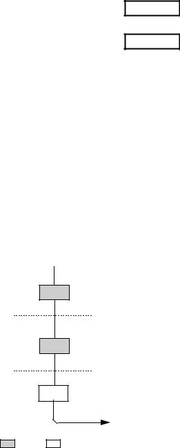
Control transfers minimally have two transaction stages: Setup and Status. A control transfer may optionally contain a Data stage between the Setup and Status stages. During the Setup stage, a SETUP transaction is used to transmit information to the control endpoint of a function. SETUP transactions are similar in format to an OUT, but use a SETUP rather than an OUT PID. Figure 8-11 shows the SETUP transaction format. A SETUP always uses a DATA0 PID for the data field of the SETUP transaction. The function receiving a SETUP must accept the SETUP data and respond with ACK, if the data is corrupted, discard the data and return no handshake.
Idle
Token SETUP
Data DATA0
Handshake ACK
Idle
Host Function
Figure 8-11. Control SETUP Transaction
The Data stage, if present, of a control transfer consists of one or more IN or OUT transactions and follows the same protocol rules as bulk transfers. All the transactions in the Data stage must be in the same direction (i.e., all INs or all OUTs). The amount of data to be sent during the data phase and its direction are specified during the Setup stage. If the amount of data exceeds the prenegotiated data packet size, the
164
Universal Serial Bus Specification Revision 1.1
data is sent in multiple transactions (INs or OUTs) that carry the maximum packet size. Any remaining data is sent as a residual in the last transaction.
The Status stage of a control transfer is the last operation in the sequence. A Status stage is delineated by a change in direction of data flow from the previous stage and always uses a DATA1 PID. If, for example, the Data stage consists of OUTs, the status is a single IN transaction. If the control sequence has no Data stage, then it consists of a Setup stage followed by a Status stage consisting of an IN transaction.
Figure 8-12 shows the transaction order, the data sequence bit value, and the data PID types for control read and write sequences. The sequence bits are displayed in parentheses.
Setup |
Data |
Stage |
Stage |
Control |
SETUP (0) |
|
OUT (1) |
|
OUT (0) |
Write |
|
|
|||
DATA0 |
|
DATA1 |
|
DATA0 |
|
|
|
|
|||
Control |
|
|
|
|
|
SETUP (0) |
|
IN (1) |
|
IN (0) |
|
Read |
|
|
|||
|
|
|
|
|
|
DATA0 |
|
DATA1 |
|
DATA0 |
|
|
|
|
|||
|
Setup |
|
Status |
|
|
|
Stage |
|
Stage |
|
|
No-data |
|
|
|
|
|
SETUP (0) |
|
IN (1) |
|
|
|
Control |
|
|
|
||
|
|
|
|
|
|
DATA0 |
|
DATA1 |
|
|
|
|
|
|
|
...
...
OUT (0/1)
DATA0/1
IN (0/1)
DATA0/1
Status
Stage
IN (1)
DATA1
OUT (1)
DATA1
Figure 8-12. Control Read and Write Sequences
When a STALL handshake is sent by a control endpoint in either the Data or Status stages of a control transfer, a STALL handshake must be returned on all succeeding accesses to that endpoint until a SETUP PID is received. The endpoint is not required to return a STALL handshake after it receives a subsequent SETUP PID.
8.5.2.1 Reporting Status Results
The Status stage reports to the host the outcome of the previous Setup and Data stages of the transfer. Three possible results may be returned:
The command sequence completed successfully.
The command sequence failed to complete.
The function is still busy completing command.
Status reporting is always in the function-to-host direction. The Table 8-5 summarizes the type of responses required for each. Control write transfers return status information in the data phase of the Status stage transaction. Control read transfers return status information in the handshake phase of a Status stage transaction, after the host has issued a zero-length data packet during the previous data phase.
165
Universal Serial Bus Specification Revision 1.1
Table 8-5. Status Stage Responses
Status Response |
Control Write Transfer |
Control Read Transfer |
|
(sent during data phase) |
(send during handshake phase) |
|
|
|
Function completes |
Zero-length data packet |
ACK handshake |
|
|
|
Function has an error |
STALL handshake |
STALL handshake |
|
|
|
Function is busy |
NAK handshake |
NAK handshake |
|
|
|
For control reads, the host sends an OUT token to the control pipe to initiate the Status stage. The host may only send a zero-length data packet in this phase but the function may accept any length packet as a valid status inquiry. The pipe’s handshake response to this data packet indicates the current status. NAK indicates that the function is still processing the command and that the host should continue the Status stage. ACK indicates that the function has completed the command and is ready to accept a new command. STALL indicates that the function has an error that prevents it from completing the command.
For control writes, the host sends an IN token to the control pipe to initiate the Status stage. The function responds with either a handshake or a zero-length data packet to indicate its current status. NAK indicates that the function is still processing the command and that the host should continue the Status stage; return of a zero-length packet indicates normal completion of the command; and STALL indicates that the function cannot complete the command. The function expects the host to respond to the data packet in the Status stage with ACK. If the function does not receive ACK, it remains in the Status stage of the command and will continue to return the zero-length data packet for as long as the host continues to send IN tokens.
If during a Data stage a command pipe is sent more data or is requested to return more data than was indicated in the Setup stage (see Section 8.5.2.2), it should return STALL. If a control pipe returns STALL during the Data stage, there will be no Status stage for that control transfer.
8.5.2.2 Variable-length Data Stage
A control pipe may have a variable-length data phase in which the host request more data than is contained in the specified data structure. When all of the data structure is returned to the host, the function should indicate that the Data stage is ended by returning a packet that is shorter than the MaxPacketSize for the pipe. If the data structure is an exact multiple of wMaxPacketSize for the pipe, the funtion will return a zero-length packet to indicate the end of the Data stage.
8.5.2.3 Error Handling on the Last Data Transaction
If the ACK handshake on an IN transaction is corrupted, the function and the host will temporarily disagree on whether the transaction was successful. If the transaction is followed by another IN, the toggle retry mechanism will detect the mismatch and recover from the error. If the ACK was on the last IN of a Data stage, the toggle retry mechanism cannot be used and an alternative scheme must be used.
The host that successfully received the data of the last IN will send ACK., Later, the host will issue an OUT token to start the Status stage of the transfer. If the function did not receive the ACK that ended the Data stage, the function will interpret the start of the Status stage as verification that the host successfully received the data. Control writes do not have this ambiguity. If an ACK handshake on an OUT gets corrupted, the host does not advance to the Status stage and retries the last data instead. A detailed analysis of retry policy is presented in Section 8.6.4.
166