

- •Chapter 1
- •1.1 Motivation
- •1.2 Objective of the Specification
- •1.3 Scope of the Document
- •1.4 Document Organization
- •Chapter 2
- •Chapter 3
- •3.1 Goals for the Universal Serial Bus
- •3.2 Taxonomy of Application Space
- •3.3 Feature List
- •Chapter 4
- •4.1 USB System Description
- •4.1.1 Bus Topology
- •4.2 Physical Interface
- •4.2.1 Electrical
- •4.2.2 Mechanical
- •4.3 Power
- •4.3.1 Power Distribution
- •4.3.2 Power Management
- •4.4 Bus Protocol
- •4.5 Robustness
- •4.5.1 Error Detection
- •4.5.2 Error Handling
- •4.6 System Configuration
- •4.6.1 Attachment of USB Devices
- •4.6.2 Removal of USB Devices
- •4.6.3 Bus Enumeration
- •4.7 Data Flow Types
- •4.7.1 Control Transfers
- •4.7.2 Bulk Transfers
- •4.7.3 Interrupt Transfers
- •4.7.4 Isochronous Transfers
- •4.7.5 Allocating USB Bandwidth
- •4.8 USB Devices
- •4.8.1 Device Characterizations
- •4.8.2 Device Descriptions
- •4.9 USB Host: Hardware and Software
- •4.10 Architectural Extensions
- •Chapter 5
- •5.1 Implementer Viewpoints
- •5.2 Bus Topology
- •5.2.1 USB Host
- •5.2.2 USB Devices
- •5.2.3 Physical Bus Topology
- •5.2.4 Logical Bus Topology
- •5.2.5 Client Software-to-function Relationship
- •5.3 USB Communication Flow
- •5.3.1 Device Endpoints
- •5.3.2 Pipes
- •5.4 Transfer Types
- •5.5 Control Transfers
- •5.5.1 Control Transfer Data Format
- •5.5.2 Control Transfer Direction
- •5.5.3 Control Transfer Packet Size Constraints
- •5.5.4 Control Transfer Bus Access Constraints
- •5.5.5 Control Transfer Data Sequences
- •5.6 Isochronous Transfers
- •5.6.1 Isochronous Transfer Data Format
- •5.6.2 Isochronous Transfer Direction
- •5.6.3 Isochronous Transfer Packet Size Constraints
- •5.6.4 Isochronous Transfer Bus Access Constraints
- •5.6.5 Isochronous Transfer Data Sequences
- •5.7 Interrupt Transfers
- •5.7.1 Interrupt Transfer Data Format
- •5.7.2 Interrupt Transfer Direction
- •5.7.3 Interrupt Transfer Packet Size Constraints
- •5.7.4 Interrupt Transfer Bus Access Constraints
- •5.7.5 Interrupt Transfer Data Sequences
- •5.8 Bulk Transfers
- •5.8.1 Bulk Transfer Data Format
- •5.8.2 Bulk Transfer Direction
- •5.8.3 Bulk Transfer Packet Size Constraints
- •5.8.4 Bulk Transfer Bus Access Constraints
- •5.8.5 Bulk Transfer Data Sequences
- •5.9 Bus Access for Transfers
- •5.9.1 Transfer Management
- •5.9.2 Transaction Tracking
- •5.9.3 Calculating Bus Transaction Times
- •5.9.4 Calculating Buffer Sizes in Functions and Software
- •5.9.5 Bus Bandwidth Reclamation
- •5.10 Special Considerations for Isochronous Transfers
- •5.10.1 Example Non-USB Isochronous Application
- •5.10.2 USB Clock Model
- •5.10.3 Clock Synchronization
- •5.10.4 Isochronous Devices
- •5.10.5 Data Prebuffering
- •5.10.6 SOF Tracking
- •5.10.7 Error Handling
- •5.10.8 Buffering for Rate Matching
- •Chapter 6
- •6.1 Architectural Overview
- •6.3 Cable
- •6.4 Cable Assembly
- •6.4.1 Detachable Cable Assemblies
- •6.4.3 Low-speed Captive Cable Assemblies
- •6.4.4 Prohibited Cable Assemblies
- •6.5.1 USB Icon Location
- •6.5.2 USB Connector Termination Data
- •6.5.3 Series “A” and Series “B” Receptacles
- •6.5.4 Series “A” and Series “B” Plugs
- •6.6.1 Description
- •6.6.2 Construction
- •6.6.3 Electrical Characteristics
- •6.6.4 Cable Environmental Characteristics
- •6.6.5 Listing
- •6.7 Electrical, Mechanical and Environmental Compliance Standards
- •6.7.1 Applicable Documents
- •6.8 USB Grounding
- •Chapter 7
- •7.1 Signaling
- •7.1.1 USB Driver Characteristics
- •7.1.2 Data Signal Rise and Fall
- •7.1.3 Cable Skew
- •7.1.4 Receiver Characteristics
- •7.1.5 Device Speed Identification
- •7.1.6 Input Characteristics
- •7.1.7 Signaling Levels
- •7.1.8 Data Encoding/Decoding
- •7.1.9 Bit Stuffing
- •7.1.10 Sync Pattern
- •7.1.11 Data Signaling Rate
- •7.1.12 Frame Interval and Frame Interval Adjustment
- •7.1.13 Data Source Signaling
- •7.1.14 Hub Signaling Timings
- •7.1.15 Receiver Data Jitter
- •7.1.16 Cable Delay
- •7.1.17 Cable Attenuation
- •7.1.18 Bus Turn-around Time and Inter-packet Delay
- •7.1.19 Maximum End-to-end Signal Delay
- •7.2 Power Distribution
- •7.2.1 Classes of Devices
- •7.2.2 Voltage Drop Budget
- •7.2.3 Power Control During Suspend/Resume
- •7.2.4 Dynamic Attach and Detach
- •7.3 Physical Layer
- •7.3.1 Regulatory Requirements
- •7.3.2 Bus Timing/Electrical Characteristics
- •7.3.3 Timing Waveforms
- •Chapter 8
- •8.1 Bit Ordering
- •8.2 SYNC Field
- •8.3 Packet Field Formats
- •8.3.1 Packet Identifier Field
- •8.3.2 Address Fields
- •8.3.3 Frame Number Field
- •8.3.4 Data Field
- •8.3.5 Cyclic Redundancy Checks
- •8.4 Packet Formats
- •8.4.1 Token Packets
- •8.4.2 Start-of-Frame Packets
- •8.4.3 Data Packets
- •8.4.4 Handshake Packets
- •8.4.5 Handshake Responses
- •8.5 Transaction Formats
- •8.5.1 Bulk Transactions
- •8.5.2 Control Transfers
- •8.5.3 Interrupt Transactions
- •8.5.4 Isochronous Transactions
- •8.6 Data Toggle Synchronization and Retry
- •8.6.1 Initialization via SETUP Token
- •8.6.2 Successful Data Transactions
- •8.6.3 Data Corrupted or Not Accepted
- •8.6.4 Corrupted ACK Handshake
- •8.6.5 Low-speed Transactions
- •8.7 Error Detection and Recovery
- •8.7.1 Packet Error Categories
- •8.7.2 Bus Turn-around Timing
- •8.7.3 False EOPs
- •8.7.4 Babble and Loss of Activity Recovery
- •Chapter 9
- •9.1 USB Device States
- •9.1.1 Visible Device States
- •9.1.2 Bus Enumeration
- •9.2 Generic USB Device Operations
- •9.2.1 Dynamic Attachment and Removal
- •9.2.2 Address Assignment
- •9.2.3 Configuration
- •9.2.4 Data Transfer
- •9.2.5 Power Management
- •9.2.6 Request Processing
- •9.2.7 Request Error
- •9.3 USB Device Requests
- •9.3.1 bmRequestType
- •9.3.2 bRequest
- •9.3.3 wValue
- •9.3.4 wIndex
- •9.3.5 wLength
- •9.4 Standard Device Requests
- •9.4.1 Clear Feature
- •9.4.2 Get Configuration
- •9.4.3 Get Descriptor
- •9.4.4 Get Interface
- •9.4.5 Get Status
- •9.4.6 Set Address
- •9.4.7 Set Configuration
- •9.4.8 Set Descriptor
- •9.4.9 Set Feature
- •9.4.10 Set Interface
- •9.4.11 Synch Frame
- •9.5 Descriptors
- •9.6 Standard USB Descriptor Definitions
- •9.6.1 Device
- •9.6.2 Configuration
- •9.6.3 Interface
- •9.6.4 Endpoint
- •9.6.5 String
- •9.7 Device Class Definitions
- •9.7.1 Descriptors
- •9.7.2 Interface(s) and Endpoint Usage
- •9.7.3 Requests
- •Chapter 10
- •10.1 Overview of the USB Host
- •10.1.1 Overview
- •10.1.2 Control Mechanisms
- •10.1.3 Data Flow
- •10.1.4 Collecting Status and Activity Statistics
- •10.1.5 Electrical Interface Considerations
- •10.2 Host Controller Requirements
- •10.2.1 State Handling
- •10.2.2 Serializer/Deserializer
- •10.2.3 Frame Generation
- •10.2.4 Data Processing
- •10.2.5 Protocol Engine
- •10.2.6 Transmission Error Handling
- •10.2.7 Remote Wakeup
- •10.2.8 Root Hub
- •10.2.9 Host System Interface
- •10.3 Overview of Software Mechanisms
- •10.3.1 Device Configuration
- •10.3.2 Resource Management
- •10.3.3 Data Transfers
- •10.3.4 Common Data Definitions
- •10.4 Host Controller Driver
- •10.5 Universal Serial Bus Driver
- •10.5.1 USBD Overview
- •10.5.2 USBD Command Mechanism Requirements
- •10.5.3 USBD Pipe Mechanisms
- •10.5.4 Managing the USB via the USBD Mechanisms
- •10.5.5 Passing USB Preboot Control to the Operating System
- •10.6 Operating System Environment Guides
- •Chapter 11
- •11.1 Overview
- •11.1.1 Hub Architecture
- •11.1.2 Hub Connectivity
- •11.2 Hub Frame Timer
- •11.2.1 Frame Timer Synchronization
- •11.2.2 EOF1 and EOF2 Timing Points
- •11.3 Host Behavior at End-of-Frame
- •11.3.1 Latest Host Packet
- •11.3.2 Packet Nullification
- •11.3.3 Transaction Completion Prediction
- •11.4 Internal Port
- •11.4.1 Inactive
- •11.4.2 Suspend Delay
- •11.4.3 Full Suspend (Fsus)
- •11.4.4 Generate Resume (GResume)
- •11.5 Downstream Ports
- •11.5.1 Downstream Port State Descriptions
- •11.6 Upstream Port
- •11.6.1 Receiver
- •11.6.2 Transmitter
- •11.7 Hub Repeater
- •11.7.1 Wait for Start of Packet from Upstream Port (WFSOPFU)
- •11.7.2 Wait for End of Packet from Upstream Port (WFEOPFU)
- •11.7.3 Wait for Start of Packet (WFSOP)
- •11.7.4 Wait for End of Packet (WFEOP)
- •11.8 Bus State Evaluation
- •11.8.1 Port Error
- •11.8.2 Speed Detection
- •11.8.3 Collision
- •11.9 Suspend and Resume
- •11.10 Hub Reset Behavior
- •11.10.1 Hub Receiving Reset on Upstream Port
- •11.11 Hub Port Power Control
- •11.11.1 Multiple Gangs
- •11.12 Hub I/O Buffer Requirements
- •11.12.1 Pull-up and Pull-down Resistors
- •11.12.2 Edge Rate Control
- •11.13 Hub Controller
- •11.13.1 Endpoint Organization
- •11.13.2 Hub Information Architecture and Operation
- •11.13.3 Port Change Information Processing
- •11.13.4 Hub and Port Status Change Bitmap
- •11.13.5 Over-current Reporting and Recovery
- •11.14 Hub Configuration
- •11.15 Descriptors
- •11.15.1 Standard Descriptors
- •11.15.2 Class-specific Descriptors
- •11.16 Requests
- •11.16.1 Standard Requests
- •11.16.2 Class-specific Requests
- •Index
Universal Serial Bus Specification Revision 1.1
When used in the toggle mode, an interrupt endpoint is initialized to the DATA0 PID by any configuration event on the endpoint and behaves the same as the bulk transactions shown in Figure 8-10.
An interrupt endpoint may also be used to communicate rate feedback information for certain types of isochronous functions. When used in this mode, the data toggle bits should be changed after each data packet is sent to the host without regard to the presence or type of handshake packet. This capability is supported only for interrupt IN endpoints.
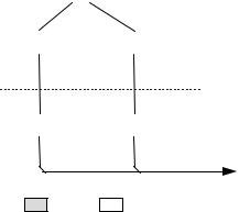
8.5.4 Isochronous Transactions
Isochronous (ISO) transactions have a token and data phase, but no handshake phase, as shown in Figure 8-14. The host issues either an IN or an OUT token followed by the data phase in which the endpoint (for INs) or the host (for OUTs) transmits data. ISO transactions do not support a handshake phase or retry capability.
|
Idle |
|
|
|
|
|
|
IN |
|
OUT |
Token |
|
|
|
|
|
|
|
Data |
DATA0/ |
|
DATA0 |
|
|
|
||
|
|
|
|
Idle
Host Function
See Note Below
Figure 8-14. Isochronous Transaction Format
Note: a device or Host Controller should be able to accept either DATA0 or DATA1. A device or Host Controller should only send DATA0.
ISO transactions do not support toggle sequencing.
8.6 Data Toggle Synchronization and Retry
The USB provides a mechanism to guarantee data sequence synchronization between data transmitter and receiver across multiple transactions. This mechanism provides a means of guaranteeing that the handshake phase of a transaction was interpreted correctly by both the transmitter and receiver. Synchronization is achieved via use of the DATA0 and DATA1 PIDs and separate data toggle sequence bits for the data transmitter and receiver. Receiver sequence bits toggle only when the receiver is able to accept data and receives an error-free data packet with the correct data PID. Transmitter sequence bits toggle only when the data transmitter receives a valid ACK handshake. The data transmitter and receiver must have their sequence bits synchronized at the start of a transaction. The synchronization mechanism used varies with the transaction type. Data toggle synchronization is not supported for ISO transfers.
168
Universal Serial Bus Specification Revision 1.1
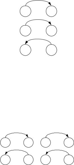
8.6.1 Initialization via SETUP Token
Control transfers use the SETUP token for initializing host and function sequence bits. Figure 8-15 shows the host issuing a SETUP packet to a function followed by an OUT transaction. The numbers in the circles represent the transmitter and receiver sequence bits. The function must accept the data and return ACK.
When the function accepts the transaction, it must set its sequence bit so that both the host’s and function’s sequence bits are equal to one at the end of the SETUP transaction.
Host |
Device |
|
SETUP |
Tx |
Rx |
(X-1) |
(X) |
|
DATA0 |
Tx |
Accept Rx |
(1)data (X->1) ACK
Tx |
Rx |
(1) |
(1) |
Figure 8-15. SETUP Initialization
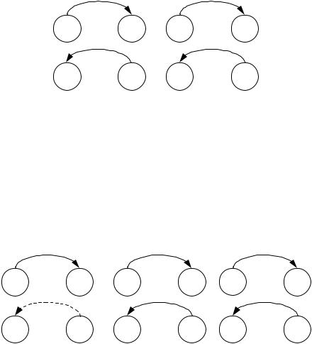
8.6.2 Successful Data Transactions
Figure 8-16 shows the case where two successful transactions have occurred. For the data transmitter, this means that it toggles its sequence bit upon receipt of ACK. The receiver toggles its sequence bit only if it receives a valid data packet and the packet’s data PID matches the current value of its sequence bit. The transmitter only toggles its sequence bit after it receives and ACK to a data packet.
During each transaction, the receiver compares the transmitter sequence bit (encoded in the data packet PID as either DATA0 or DATA1) with its receiver sequence bit. If data cannot be accepted, the receiver must issue NAK and the sequence bits of both the transmitter and receiver remain unchanged. If data can be accepted and the receiver’s sequence bit matches the PID sequence bit, then data is accepted and the sequence bit is toggled. Two-phase transactions in which there is no data packet leave the transmitter and receiver sequence bits unchanged.
DATA0 DATA1
Tx |
Accept |
Rx |
Tx |
Accept |
Rx |
(0) |
data |
(0->1) |
(1) |
data |
(1->0) |
|
ACK |
|
|
ACK |
|
Tx |
|
Rx |
Tx |
|
Rx |
(0->1) |
|
(1) |
(1->0) |
|
(0) |
|
Transfer i |
|
|
Transfer i + 1 |
|
Figure 8-16. Consecutive Transactions
169
Universal Serial Bus Specification Revision 1.1
8.6.3 Data Corrupted or Not Accepted
If data cannot be accepted or the received data packet is corrupted, the receiver will issue a NAK or STALL handshake, or timeout, depending on the circumstances, and the receiver will not toggle its sequence bit. Figure 8-17 shows the case where a transaction is NAKed and then retried. Any non-ACK handshake or timeout will generate similar retry behavior. The transmitter, having not received an ACK handshake, will not toggle its sequence bit. As a result, a failed data packet transaction leaves the transmitter’s and receiver’s sequence bits synchronized and untoggled. The transaction will then be retried and, if successful, will cause both transmitter and receiver sequence bits to toggle.
DATA0 DATA0
Tx |
Reject |
Rx |
Tx |
Accept |
Rx |
(0) |
data |
(0->0) |
(0) |
data |
(0->1) |
|
NAK |
|
|
ACK |
|
Tx |
|
Rx |
Tx |
|
Rx |
(0->0) |
|
(0) |
(0->1) |
|
(1) |
|
Transfer i |
|
|
Retry |
|
|
|
|
|
Transfer i |
|
Figure 8-17. NAKed Transaction with Retry
8.6.4 Corrupted ACK Handshake
The transmitter is the last and only agent to know for sure whether a transaction has been successful, due to its receiving an ACK handshake. A lost or corrupted ACK handshake can lead to a temporary loss of synchronization between transmitter and receiver as shown in Figure 8-18. Here the transmitter issues a valid data packet, which is successfully acquired by the receiver; however, the ACK handshake is corrupted.
|
DATA0 |
|
|
DATA0 |
|
|
DATA1 |
Tx |
Accept |
Rx |
Tx |
Ignore |
Rx |
Tx |
Rx |
(0) |
data |
(0->1) |
(0) |
data |
(1) |
(1) |
(1->0) |
|
Failed ACK |
|
|
ACK |
|
|
ACK |
Tx |
|
Rx |
Tx |
|
Rx |
Tx |
Rx |
(0->0) |
|
(1) |
(0->1) |
|
(1) |
(1->0) |
(0) |
|
Transfer i |
|
|
Transfer i |
|
|
Transfer i + 1 |
|
|
|
|
(retried) |
|
|
|
Figure 8-18. Corrupted ACK Handshake with Retry
At the end of transaction i, there is a temporary loss of coherency between transmitter and receiver, as evidenced by the mismatch between their respective sequence bits. The receiver has received good data, but the transmitter does not know whether it has successfully sent data. On the next transaction, the transmitter will resend the previous data using the previous DATA0 PID. The receiver’s sequence bit and the data PID will not match, so the receiver knows that it has previously accepted this data. Consequently, it discards the incoming data packet and does not toggle its sequence bit. The receiver then issues ACK, which causes the transmitter to regard the retried transaction as successful. Receipt of ACK causes the
170
Universal Serial Bus Specification Revision 1.1
transmitter to toggle its sequence bit. At the beginning of transaction i+1, the sequence bits have toggled and are again synchronized.
The data transmitter must guarantee that any retried data packet is identical (same length and content) as that sent in the original transaction. If the data transmitter is unable, because of problems such as a buffer underrun condition, to transmit the identical amount of data as was in the original data packet, it must abort the transaction by generating a bit stuffing violation. This causes a detectable error at the receiver and guarantees that a partial packet will not be interpreted as a good packet. The transmitter should not try to force an error at the receiver by sending a known bad CRC. A combination of a bad packet with a “bad” CRC may be interpreted by the receiver as a good packet.
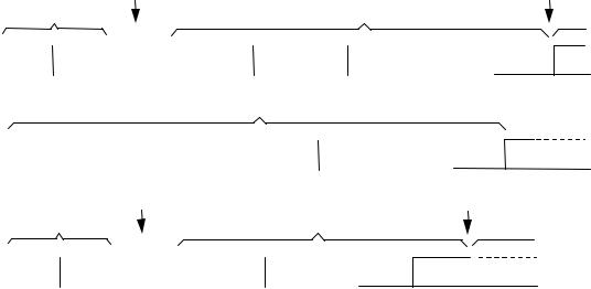
8.6.5 Low-speed Transactions
The USB supports signaling at two speeds: full-speed signaling at 12.0Mb/s and low-speed signaling at 1.5Mb/s. Hubs disable downstream bus traffic to all ports to which low-speed devices are attached during full-speed downstream signaling. This is required both for EMI reasons and to prevent any possibility that a low-speed device might misinterpret downstream a full-speed packet as being addressed to it.
Figure 8-19 shows an IN low-speed transaction in which the host issues a token and handshake and receives a data packet.
|
|
|
|
|
|
|
|
|
|
|
|
|
|
|
Hub enables low- |
|
|
|
|
|
|
Hub disables low- |
|||
|
|
|
|
|
|
|
|
|
|
|
|
|
|
|
speed port outputs |
|
|
|
|
|
|
speed port outputs |
|||
|
|
|
|
Preamble |
|
|
|
|
|
|
|
|
Token sent at low-speed |
|
|
||||||||||
sent at full-speed |
|
|
|
|
|
|
|
|
|
|
|||||||||||||||
|
|
|
|
|
|
|
|
|
|
|
|
|
|||||||||||||
|
|
|
|
|
|
|
|
|
|
|
|
|
|
|
|
|
|
|
|
|
|
|
|
|
|
|
|
|
|
|
|
|
|
|
|
|
|
|
|
|
|
|
|
|
|
|
|
|
|
|
|
|
|
|
|
|
|
|
|
|
|
|
|
|
|
Hub setup |
|
|
|
|
|
ENDP |
. . . |
|
|
||
|
SYNC |
|
|
PID |
|
|
|
|
|
|
SYNC |
|
|
PID |
|
EOP |
|||||||||
|
|
|
|
|
|
|
|
|
|
||||||||||||||||
|
|
|
|
|
|
|
|
|
|
|
|
|
|
|
|
|
|
|
|
|
|
|
|
|
|
|
|
|
|
|
|
|
|
|
|
|
|
|
|
|
|
|
|
Data packet sent at low-speed |
|
|
|
|
|||
|
|
|
|
|
|
|
|
|
|
|
|
|
|
|
|
|
|
|
|
|
|
|
|
|
|
|
|
|
|
|
SYNC |
|
|
|
|
|
|
|
|
PID |
|
DATA |
CRC |
|
EOP |
||||||
|
|
|
|
|
|
|
|
|
|
|
|
|
|
|
|
|
|
|
|
|
|
|
|
|
|
|
|
|
|
|
|
|
|
|
|
|
|
|
|
|
|
|
|
|
|
|
|
|
Hub disables low- |
||
|
|
|
|
|
|
|
|
|
|
|
|
|
|
|
|
|
|
|
|
|
|
|
|||
|
|
|
|
|
|
|
|
|
|
|
|
|
|
|
|
Hub enables low- |
|
|
|
|
speed port outputs |
||||
|
|
|
|
|
|
|
|
|
|
|
|
|
|
|
|
|
|
|
|
||||||
|
|
|
|
|
Preamble |
|
|
speed port outputs |
|
|
|
|
|
|
|||||||||||
|
|
|
sent at full-speed |
|
|
|
|
|
|
|
Handshake sent at low-speed |
|
|
|
|||||||||||
|
|
|
|
|
|
|
|
|
|
|
|
|
|||||||||||||
|
|
|
|
|
|
|
|
|
|
|
|
|
|
|
|
|
|
|
|
|
|
|
|
|
|
|
|
|
|
|
|
|
|
|
|
|
|
|
|
|
|
|
|
|
|
|
|
|
|
|
|
|
|
|
|
|
|
|
|
|
|
|
|
|
|
|
Hub setup |
SYNC |
|
|
PID |
EOP |
|
|
|
||
|
|
|
|
|
|
|
|
|
|
|
|
|
|
||||||||||||
|
|
|
SYNC |
|
|
|
PID |
|
|
|
|
|
|
|
|
|
|
||||||||
|
|
|
|
|
|
|
|
|
|
|
|
|
|||||||||||||
|
|
|
|
|
|
|
|
|
|
|
|
|
|||||||||||||
|
|
|
|
|
|
|
|
|
|
|
|
|
|
|
|
|
|
|
|
|
|
|
|
|
|
|
|
|
|
|
|
|
|
|
|
|
|
|
|
|
|
|
|
|
|
|
|
|
|
|
|
Figure 8-19. Low-speed Transaction
All downstream packets transmitted to low-speed devices require a preamble. The preamble consists of a SYNC followed by a PRE PID, both sent at full-speed. Hubs must comprehend the PRE PID; all other USB devices may ignore it and treat it as undefined. After the end of the preamble PID, the host must wait at least four full-speed bit times during which hubs must complete the process of enabling the repeater function on ports that are connected to low-speed devices. During this hub setup interval, hubs must drive their full-speed and low-speed ports to their respective Idle states. Hubs must be ready to repeat low-speed signaling on low-speed ports before the end of the hub setup interval. Low-speed connectivity rules are summarized below:
1.Low-speed devices are identified during the connection process and the hub ports to which they are connected are identified as low-speed.
2.All downstream low-speed packets must be prefaced with a preamble (sent at full-speed), which turns on the output buffers on low-speed hub ports.
171