

- •Chapter 1
- •1.1 Motivation
- •1.2 Objective of the Specification
- •1.3 Scope of the Document
- •1.4 Document Organization
- •Chapter 2
- •Chapter 3
- •3.1 Goals for the Universal Serial Bus
- •3.2 Taxonomy of Application Space
- •3.3 Feature List
- •Chapter 4
- •4.1 USB System Description
- •4.1.1 Bus Topology
- •4.2 Physical Interface
- •4.2.1 Electrical
- •4.2.2 Mechanical
- •4.3 Power
- •4.3.1 Power Distribution
- •4.3.2 Power Management
- •4.4 Bus Protocol
- •4.5 Robustness
- •4.5.1 Error Detection
- •4.5.2 Error Handling
- •4.6 System Configuration
- •4.6.1 Attachment of USB Devices
- •4.6.2 Removal of USB Devices
- •4.6.3 Bus Enumeration
- •4.7 Data Flow Types
- •4.7.1 Control Transfers
- •4.7.2 Bulk Transfers
- •4.7.3 Interrupt Transfers
- •4.7.4 Isochronous Transfers
- •4.7.5 Allocating USB Bandwidth
- •4.8 USB Devices
- •4.8.1 Device Characterizations
- •4.8.2 Device Descriptions
- •4.9 USB Host: Hardware and Software
- •4.10 Architectural Extensions
- •Chapter 5
- •5.1 Implementer Viewpoints
- •5.2 Bus Topology
- •5.2.1 USB Host
- •5.2.2 USB Devices
- •5.2.3 Physical Bus Topology
- •5.2.4 Logical Bus Topology
- •5.2.5 Client Software-to-function Relationship
- •5.3 USB Communication Flow
- •5.3.1 Device Endpoints
- •5.3.2 Pipes
- •5.4 Transfer Types
- •5.5 Control Transfers
- •5.5.1 Control Transfer Data Format
- •5.5.2 Control Transfer Direction
- •5.5.3 Control Transfer Packet Size Constraints
- •5.5.4 Control Transfer Bus Access Constraints
- •5.5.5 Control Transfer Data Sequences
- •5.6 Isochronous Transfers
- •5.6.1 Isochronous Transfer Data Format
- •5.6.2 Isochronous Transfer Direction
- •5.6.3 Isochronous Transfer Packet Size Constraints
- •5.6.4 Isochronous Transfer Bus Access Constraints
- •5.6.5 Isochronous Transfer Data Sequences
- •5.7 Interrupt Transfers
- •5.7.1 Interrupt Transfer Data Format
- •5.7.2 Interrupt Transfer Direction
- •5.7.3 Interrupt Transfer Packet Size Constraints
- •5.7.4 Interrupt Transfer Bus Access Constraints
- •5.7.5 Interrupt Transfer Data Sequences
- •5.8 Bulk Transfers
- •5.8.1 Bulk Transfer Data Format
- •5.8.2 Bulk Transfer Direction
- •5.8.3 Bulk Transfer Packet Size Constraints
- •5.8.4 Bulk Transfer Bus Access Constraints
- •5.8.5 Bulk Transfer Data Sequences
- •5.9 Bus Access for Transfers
- •5.9.1 Transfer Management
- •5.9.2 Transaction Tracking
- •5.9.3 Calculating Bus Transaction Times
- •5.9.4 Calculating Buffer Sizes in Functions and Software
- •5.9.5 Bus Bandwidth Reclamation
- •5.10 Special Considerations for Isochronous Transfers
- •5.10.1 Example Non-USB Isochronous Application
- •5.10.2 USB Clock Model
- •5.10.3 Clock Synchronization
- •5.10.4 Isochronous Devices
- •5.10.5 Data Prebuffering
- •5.10.6 SOF Tracking
- •5.10.7 Error Handling
- •5.10.8 Buffering for Rate Matching
- •Chapter 6
- •6.1 Architectural Overview
- •6.3 Cable
- •6.4 Cable Assembly
- •6.4.1 Detachable Cable Assemblies
- •6.4.3 Low-speed Captive Cable Assemblies
- •6.4.4 Prohibited Cable Assemblies
- •6.5.1 USB Icon Location
- •6.5.2 USB Connector Termination Data
- •6.5.3 Series “A” and Series “B” Receptacles
- •6.5.4 Series “A” and Series “B” Plugs
- •6.6.1 Description
- •6.6.2 Construction
- •6.6.3 Electrical Characteristics
- •6.6.4 Cable Environmental Characteristics
- •6.6.5 Listing
- •6.7 Electrical, Mechanical and Environmental Compliance Standards
- •6.7.1 Applicable Documents
- •6.8 USB Grounding
- •Chapter 7
- •7.1 Signaling
- •7.1.1 USB Driver Characteristics
- •7.1.2 Data Signal Rise and Fall
- •7.1.3 Cable Skew
- •7.1.4 Receiver Characteristics
- •7.1.5 Device Speed Identification
- •7.1.6 Input Characteristics
- •7.1.7 Signaling Levels
- •7.1.8 Data Encoding/Decoding
- •7.1.9 Bit Stuffing
- •7.1.10 Sync Pattern
- •7.1.11 Data Signaling Rate
- •7.1.12 Frame Interval and Frame Interval Adjustment
- •7.1.13 Data Source Signaling
- •7.1.14 Hub Signaling Timings
- •7.1.15 Receiver Data Jitter
- •7.1.16 Cable Delay
- •7.1.17 Cable Attenuation
- •7.1.18 Bus Turn-around Time and Inter-packet Delay
- •7.1.19 Maximum End-to-end Signal Delay
- •7.2 Power Distribution
- •7.2.1 Classes of Devices
- •7.2.2 Voltage Drop Budget
- •7.2.3 Power Control During Suspend/Resume
- •7.2.4 Dynamic Attach and Detach
- •7.3 Physical Layer
- •7.3.1 Regulatory Requirements
- •7.3.2 Bus Timing/Electrical Characteristics
- •7.3.3 Timing Waveforms
- •Chapter 8
- •8.1 Bit Ordering
- •8.2 SYNC Field
- •8.3 Packet Field Formats
- •8.3.1 Packet Identifier Field
- •8.3.2 Address Fields
- •8.3.3 Frame Number Field
- •8.3.4 Data Field
- •8.3.5 Cyclic Redundancy Checks
- •8.4 Packet Formats
- •8.4.1 Token Packets
- •8.4.2 Start-of-Frame Packets
- •8.4.3 Data Packets
- •8.4.4 Handshake Packets
- •8.4.5 Handshake Responses
- •8.5 Transaction Formats
- •8.5.1 Bulk Transactions
- •8.5.2 Control Transfers
- •8.5.3 Interrupt Transactions
- •8.5.4 Isochronous Transactions
- •8.6 Data Toggle Synchronization and Retry
- •8.6.1 Initialization via SETUP Token
- •8.6.2 Successful Data Transactions
- •8.6.3 Data Corrupted or Not Accepted
- •8.6.4 Corrupted ACK Handshake
- •8.6.5 Low-speed Transactions
- •8.7 Error Detection and Recovery
- •8.7.1 Packet Error Categories
- •8.7.2 Bus Turn-around Timing
- •8.7.3 False EOPs
- •8.7.4 Babble and Loss of Activity Recovery
- •Chapter 9
- •9.1 USB Device States
- •9.1.1 Visible Device States
- •9.1.2 Bus Enumeration
- •9.2 Generic USB Device Operations
- •9.2.1 Dynamic Attachment and Removal
- •9.2.2 Address Assignment
- •9.2.3 Configuration
- •9.2.4 Data Transfer
- •9.2.5 Power Management
- •9.2.6 Request Processing
- •9.2.7 Request Error
- •9.3 USB Device Requests
- •9.3.1 bmRequestType
- •9.3.2 bRequest
- •9.3.3 wValue
- •9.3.4 wIndex
- •9.3.5 wLength
- •9.4 Standard Device Requests
- •9.4.1 Clear Feature
- •9.4.2 Get Configuration
- •9.4.3 Get Descriptor
- •9.4.4 Get Interface
- •9.4.5 Get Status
- •9.4.6 Set Address
- •9.4.7 Set Configuration
- •9.4.8 Set Descriptor
- •9.4.9 Set Feature
- •9.4.10 Set Interface
- •9.4.11 Synch Frame
- •9.5 Descriptors
- •9.6 Standard USB Descriptor Definitions
- •9.6.1 Device
- •9.6.2 Configuration
- •9.6.3 Interface
- •9.6.4 Endpoint
- •9.6.5 String
- •9.7 Device Class Definitions
- •9.7.1 Descriptors
- •9.7.2 Interface(s) and Endpoint Usage
- •9.7.3 Requests
- •Chapter 10
- •10.1 Overview of the USB Host
- •10.1.1 Overview
- •10.1.2 Control Mechanisms
- •10.1.3 Data Flow
- •10.1.4 Collecting Status and Activity Statistics
- •10.1.5 Electrical Interface Considerations
- •10.2 Host Controller Requirements
- •10.2.1 State Handling
- •10.2.2 Serializer/Deserializer
- •10.2.3 Frame Generation
- •10.2.4 Data Processing
- •10.2.5 Protocol Engine
- •10.2.6 Transmission Error Handling
- •10.2.7 Remote Wakeup
- •10.2.8 Root Hub
- •10.2.9 Host System Interface
- •10.3 Overview of Software Mechanisms
- •10.3.1 Device Configuration
- •10.3.2 Resource Management
- •10.3.3 Data Transfers
- •10.3.4 Common Data Definitions
- •10.4 Host Controller Driver
- •10.5 Universal Serial Bus Driver
- •10.5.1 USBD Overview
- •10.5.2 USBD Command Mechanism Requirements
- •10.5.3 USBD Pipe Mechanisms
- •10.5.4 Managing the USB via the USBD Mechanisms
- •10.5.5 Passing USB Preboot Control to the Operating System
- •10.6 Operating System Environment Guides
- •Chapter 11
- •11.1 Overview
- •11.1.1 Hub Architecture
- •11.1.2 Hub Connectivity
- •11.2 Hub Frame Timer
- •11.2.1 Frame Timer Synchronization
- •11.2.2 EOF1 and EOF2 Timing Points
- •11.3 Host Behavior at End-of-Frame
- •11.3.1 Latest Host Packet
- •11.3.2 Packet Nullification
- •11.3.3 Transaction Completion Prediction
- •11.4 Internal Port
- •11.4.1 Inactive
- •11.4.2 Suspend Delay
- •11.4.3 Full Suspend (Fsus)
- •11.4.4 Generate Resume (GResume)
- •11.5 Downstream Ports
- •11.5.1 Downstream Port State Descriptions
- •11.6 Upstream Port
- •11.6.1 Receiver
- •11.6.2 Transmitter
- •11.7 Hub Repeater
- •11.7.1 Wait for Start of Packet from Upstream Port (WFSOPFU)
- •11.7.2 Wait for End of Packet from Upstream Port (WFEOPFU)
- •11.7.3 Wait for Start of Packet (WFSOP)
- •11.7.4 Wait for End of Packet (WFEOP)
- •11.8 Bus State Evaluation
- •11.8.1 Port Error
- •11.8.2 Speed Detection
- •11.8.3 Collision
- •11.9 Suspend and Resume
- •11.10 Hub Reset Behavior
- •11.10.1 Hub Receiving Reset on Upstream Port
- •11.11 Hub Port Power Control
- •11.11.1 Multiple Gangs
- •11.12 Hub I/O Buffer Requirements
- •11.12.1 Pull-up and Pull-down Resistors
- •11.12.2 Edge Rate Control
- •11.13 Hub Controller
- •11.13.1 Endpoint Organization
- •11.13.2 Hub Information Architecture and Operation
- •11.13.3 Port Change Information Processing
- •11.13.4 Hub and Port Status Change Bitmap
- •11.13.5 Over-current Reporting and Recovery
- •11.14 Hub Configuration
- •11.15 Descriptors
- •11.15.1 Standard Descriptors
- •11.15.2 Class-specific Descriptors
- •11.16 Requests
- •11.16.1 Standard Requests
- •11.16.2 Class-specific Requests
- •Index
Universal Serial Bus Specification Revision 1.1
Chapter 11
Hub Specification
This chapter describes the architectural requirements for the USB hub. It contains a description of the two principal sub-blocks: the Hub Repeater and the Hub Controller. The chapter also describes the hub's operation for error recovery, reset, and suspend/resume. The second half of the chapter defines hub request behavior and hub descriptors.
The hub specification supplies sufficient additional information to permit an implementer to design a hub that conforms to the USB specification.
11.1 Overview
Hubs provide the electrical interface between USB devices and the host. Hubs are directly responsible for supporting many of the attributes that make USB user friendly and hide its complexity from the user. Listed below are the major aspects of USB functionality that hubs must support:
Connectivity behavior
Power management
Device connect/disconnect detection
Bus fault detection and recovery
Fulland low-speed device support.
A hub consists of two components: the Hub Repeater and the Hub Controller. The Hub Repeater is responsible for connectivity setup and tear-down. It also supports exception handling, such as bus fault detection and recovery and connect/disconnect detect. The Hub Controller provides the mechanism for host-to-hub communication. Hub-specific status and control commands permit the host to configure a hub and to monitor and control its individual downstream ports.
229
Universal Serial Bus Specification Revision 1.1
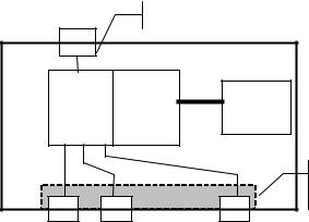
11.1.1 Hub Architecture
Figure 11-1 shows a hub and the locations of its upstream and downstream ports. A hub consists of a Hub Repeater section and a Hub Controller section. The Hub Repeater is responsible for managing connectivity on a per-packet basis, while the Hub Controller provides status and control and permits host access to the hub.
Port 0
Upstream Port |
Upstream Port State Machine |
Hub |
|
Hub |
Hub |
|
Repeater |
State |
|||
Controller |
||||
|
|
Machine |
||
|
|
|
||
|
|
... |
|
|
Port 1 |
Port 2 |
Port N |
||
Downstream Ports
Figure 11-1. Hub Architecture
Downstream Port
State Machine(s)
11.1.2 Hub Connectivity
Hubs display differing connectivity behavior, depending on whether they are propagating packet traffic or resume signaling, or are in the Idle state.
230
Universal Serial Bus Specification Revision 1.1
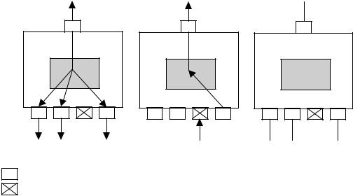
11.1.2.1 Packet Signaling Connectivity
The Hub Repeater contains one port that must always connect in the upstream direction (referred to as the upstream port) and one or more downstream ports. Upstream connectivity is defined as being towards the host, and downstream connectivity is defined as being towards a device. Figure 11-2 shows the packet signaling connectivity behavior for hubs in the upstream and downstream directions. A hub also has an Idle state, during which the hub makes no connectivity. When in the Idle state, all of the hub’s ports are in the receive mode waiting for the start of the next packet.
Upstream |
Port |
Downstream
Ports
Downstream |
Upstream |
Idle |
Connectivity |
Connectivity |
(No Connectivity) |
Enabled Port
Port not Enabled
Figure 11-2. Hub Signaling Connectivity
If a downstream hub port is enabled (i.e., in a state where it can propagate signaling through the hub) and the hub detects a Start-of-Packet (SOP) on that port, connectivity is established in an upstream direction to the upstream port of that hub, but not to any other downstream ports. This means that when a device or a hub transmits a packet upstream, only those hubs in line between the transmitting device and the host will see the packet. Refer to Section 11.8.3 for optional behavior when a hub detects simultaneous upstream signaling on more than one port.
In the downstream direction, hubs operate in a broadcast mode. When a hub detects an SOP on its upstream port, it establishes connectivity to all enabled downstream ports. If a port is not enabled, it does not propagate packet signaling downstream.
231