

Appendix A
IEEE 802.11A/E SIMULATION TOOL “WARP2”
A.1 |
Traffic Models .................................................................... |
216 |
A.2 |
IEEE 802.11 MAC Implementation.................................. |
216 |
A.3 |
Radio Channel and PHY Capture Model......................... |
217 |
A.4 |
Results................................................................................. |
217 |
A.5 |
User Interface..................................................................... |
219 |
WARP2 stands for Wireless Access Radio Protocol, where the number 2 refers to the HiperLAN/2 protocol. The simulator was developed in Kadelka (2001) and Esseling et al. (2001) as simulation environment
for the HiperLAN/2 protocol. In WARP2, the HiperLAN/2 protocol is specified in the graphical representation of the System Description Language (SDL) and the Abstract Syntax Notation (ASN.1) with the usage of the commercial tool Telelogic TAU SDTTM. With this tool, stand-alone simulators can be generated that allow tests of the specified protocols. For in depth analysis and event driven simulation, a modified version of the ComNets Class Library (CNCL) and the ComNets ReadDefaults tool have been attached to the protocol specification, making WARP2 suitable for the simulation of large scenarios with detailed specifications of complete protocols.
For this thesis, the WARP2 simulator was extended by a complete specification of the 802.11 MAC protocol including the 802.11e QoS enhancements, and a model of the 802.11a PHY with the OFDM radio transmission scheme, which allows simulation of 802.11 in parallel to the HiperLAN/2 protocol. Further, the channel model as described in Section 2.4 and Appendix C was implemented, and a JAVA-based graphical user interface was added. Contributions from the following works have been integrated in the 802.11 part of the simulation tool WARP2:

216 |
A: IEEE 802.11a/e Simulation Tool “WARP2” |
Forkel (1999), Easo (1999), Wijaya (1999), Hmaimou (2000), Wiemann (2000), Badali (2001), Hiertz (2002), and Berlemann (2002).18
A.1 Traffic Models
Various models that generate typical Internet traffic can be used as offered traffic for MSDU Deliveries in single-hop station-to-station links or in multi-hop routes where MSDUs are forwarded over more than two stations. In WARP2, multi-hop routes are static, which means the list of stations by which a particular route is defined remains constant throughout a simulation. The traffic generators used in WARP2 allow the application of constantly distributed and negativeexponentially distributed inter-arrival times of the generated packets. The generated packets are fed into the MAC layers as part of the frame body of MSDUs. The constant inter-arrival time can be used to simulate highly correlated offers such as an N-ISDN voice source with a constant bit rate of 64 kbit/s. The nega- tive-exponentially distributed inter-arrival times can be used to simulate uncorrelated offers such as best-effort Ethernet traffic. In addition, traces of recorded real life inter-arrival processes of traffic sources, which include packet lengths, can be used to simulate realistic LAN and Moving Pictures Expert Group (MPEG) video, i.e., MPEG-1 offers (see Bellcore 2000 and Garret 2000).
To investigate the interaction between the protocols and the Transport Control Protocol (TCP) and Internet Protocol (IP) stack, a TCP/IP model with File Transfer Protocol (FTP) and Hypertext Transfer Protocol (HTTP) applications are available, but not used in this thesis. All traffic generators can be mixed to model complicated scenarios where each station carries multiple applications at the same time.
A.2 IEEE 802.11 MAC Implementation
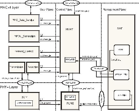
Figure A.1 illustrates the implementation of the 802.11 protocol in WARP2. Shown are the models for MAC and PHY layers, that are connected to traffic generators, stochastic evaluation, and the radio channel model. However, any number of stations can be simulated by instantiating numerous entities of the 802.11 protocol. It is defined in some parameter files where the stations are positioned and in case they are mobile, along what route they move throughout the simulation.
18The diploma theses referred to in this thesis, including all cited diploma theses in the bibliography, have been supervised by the author of this thesis.
A.3: Radio Channel and PHY Capture Model |
217 |
A.3 Radio Channel and PHY Capture Model
The channel model as described in Section 2.1 and Appendix C is implemented in WARP2, including power control, link adaptation, and a simplified mobility model. Further, a complex model of PHY capture is implemented in WARP2. This PHY capture happens when a receiving station is synchronizing its reception to a particular burst by receiving a valid preamble from that burst, and at some point in time during synchronization, this receiving station is detecting another preamble from another transmission of a second transmitting station, at a higher power level. In this case, it may happen that the second transmitting station captures the synchronization, and as a result, the receiving station attempts to receive the burst from the second transmitting station instead of the first burst. In the model that is implemented in the WARP2 simulator, it is assumed that the PHY capture occurs if the receiving power of the second burst is at least twice as high as the receiving power of the ongoing synchronization. The success of the synchronization itself is calculated based on the PER requirements of a short frame transmitted with BPSK1/2. A detailed model of the timing during synchronization is required in simulation of the 802.11 protocol, since according to the 802.11 standard, stations have to react differently when receiving bursts from stations that transmit simultaneously, but with different starting times. Received powers at a station depend on the transmitting powers and distances between stations. Throughout this thesis, the attenuation model as given in Equation (2.3) is used withγ = 3.5 , if not stated otherwise. Transmit powers are typically 23 dBm , but may change dynamically from frame to frame when dynamic transmit power control is applied by a station.
A.4 Results
The results of the stochastic simulation are the throughput per route (a route may be a single hop), the backoff delays per access category at any backoff entity within any station, and the MSDU Delivery delays per route (per multi hop or per single hop). All results can be given per access category for every station individually, or averaged over all stations of the scenario.
Further, beacon delays and collision probabilities can be evaluated, as well as any parameters of the random backoff processes, such as contention window sizes. With WARP2, event-driven, stochastic simulation is used to calculate long runs of realistic scenarios. For the delay results of the MSDU Delivery and backoff delays, empirical distribution functions of the resulting stochastic data can be given, in this thesis presented as Complementary Cumulative Distribution Func-
218 |
A: IEEE 802.11a/e Simulation Tool “WARP2” |
tions (CCDFs). The discrete Limited Relative Error (LRE) algorithm that measures the local correlation of the stochastic data is used.
See Schreiber (1988) and Görg (1997) for an explanation of the LRE algorithm. With this algorithm, by measuring local correlations, the accuracy of empirical simulation results can be estimated. All WARP2 results that are presented in this thesis are within a maximum limited relative error of 5 %. This maximum limited relative error is the level of confidence all WARP2 results are calculated with.
Figure A.1: Implementation of the IEEE 802.11 MAC and PHY layer. Shown are user, control, and management plane. Packets are fed into an instance of the MAC user plane by traffic generators. The physical layer forwards MPDUs through a channel to other stations.

A.5: User Interface |
219 |
A.5 User Interface
Figure A.2 shows the user interface of the WARP2 simulation tool.
Figure A.2: User interface of the WARP2 simulation tool. Shown are frame exchanges between eight 802.11e stations, including beacon and QoS CF-Poll.