

46 |
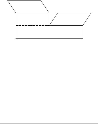
4. IEEE 802.11e Hybrid Coordination Function |
time bounded services: QoS guarantee
Controlled Channel Access, as part of Hybrid Coord. Function (HCF)
differentiated services: QoS support
with priorities
Contention-based Channel Access (Enhanced DCF), as part of Hybrid Coordination Function (HCF)
Figure 4.1: 802.11e coordination function HCF.
The priorities correspond to Annex H.2 of IEEE 802.1D (1998), and are summarized in Table 4.1. The EDCF parameter sets define the priorities in channel access by modifying the backoff process with individual interframe spaces, contention windows and many more parameters per AC, as explained in the following.
4.2.2EDCF Parameter Sets per AC
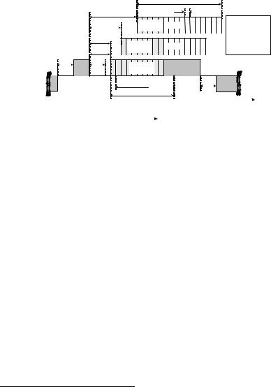
The contention-based channel access is realized with the EDCF parameter sets per AC. Which values to be used by which backoff entity is defined by the HC. The EDCF parameters can be adapted over time by the HC, and are announced via information fields in the beacon frames. Figure 4.3 illustrates the distributed nature of this approach. A QBSS with some activities on the radio channel is shown in the figure. The identical EDCF parameters must be used by the different backoff entities of the same AC. Any active schedule of MSDUs waiting in different queues, and any individual change of EDCF parameters within a station will violate the standard.
Table 4.1: Priority – AC mapping (IEEE 802.11 WG, 2002a)
802.1D |
802.1D Interpretation |
802.11e |
Service Type |
|
Priority |
AC |
|||
|
|
|||
|
|
|
|
|
0 |
Best Effort |
0 |
best effort |
|
1 |
Background |
0 |
best effort |
|
2 |
- |
0 |
best effort |
|
3 |
Excellent Effort |
1 |
video probe |
|
4 |
Controlled Load |
2 |
video |
|
5 |
Video < 100ms delay and delay variation |
2 |
video |
|
6 |
Voice, video < 10ms delay and delay variation |
3 |
voice/video |
|
7 |
Network Control |
3 |
network control |
|
|
|
|
|
4.2 Hybrid Coordination Function, Contention-based Channel Access |
|
|
|
|
|
47 |
|||||||||||
legacy 802.11 station |
IEEE 802.11e station with four backoff entities: |
|
|
||||||||||||||
with one backoff entity: |
|
|
|
|
|
|
|
|
|
|
|
|
|
|
|
|
|
|
|
|
|
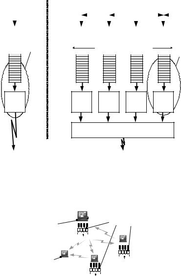
8 priorities 0 |
- 7 according to 802.1D are |
|
|
|
|
||||||||
|
|
|
|
mapped to 4 Access Categories (ACs) |
|
|
|
|
|||||||||
|
|
7 |
6 |
5 |
4 |
3 |
2 |
|
1 |
|
0 |
|
|||||
|
|
|
|
|
|
|
|
|
|
|
|
|
|
|
|
|
|
|
|
|
|
|
|
|
|
|
|
|
|
|
|
|
|
|
|
|
|
|
|
|
|
|
|
|
|
|
|
|
|
|
|
|
|
|
|
|
|
|
|
|
|
|
|
|
|
|
|
|
|
|
|
one priority |
4 Access Categories AC0 - AC3 representing 4 |
|
priorities, with 4 independent backoff entities |
||
|
backoff |
higher priority |
|
entity |
AC3 |
AC2 |
|
lower priority
AC1 |
AC0 |
backoff |
|
entity |
|||
|
|
backoff |
PF[AC] not |
backoff |
backoff |
backoff |
backoff |
(DIFS) |
(AIFSN) |
(AIFSN) |
(AIFSN) |
(AIFSN) |
|
(15) |
part of |
(CWmin) |
(CWmin) |
(CWmin) |
(CWmin) |
(1023) |
802.11e |
(CWmax) |
(CWmax) |
(CWmax) |
(CWmax) |
|
|
upon parallel access at the same slot, the higher priority |
|||
|
|
AC backoff entity transmits, the other backoff entity/ |
|||
|
|
|
entities act as if a collision occured |
|
|
transmission |
AIFSN = 1,2,3… |
|
transmission |
|
|
AIFS = SIFS + aSlotTime x AIFSN |
|
||||
|
|
||||
|
|
|
|||
Figure 4.2: Legacy 802.11 station and 802.11e station with four ACs within one station. The abbreviations used in the figure are explained in Section 4.2.2.
This violation will break the consistency of the protocol because in this case MSDUs delivered by backoff entities of different stations but within one AC will observe different QoS. In an QIBSS, the beacon holder is responsible for defining the EDCF parameters.
|
|
|
|
|
|
Access |
equal QoS parameters |
|||||
|
|
|
|
|
|
|
Point |
for this AC, used by all |
||||
the HC residing in the AP |
|
|
|
|
|
uplink |
backoff entities in this AC |
|||||
|
|
|
|
|
||||||||
|
|
|
|
|
|
|
|
|||||
broadcasts QoS parameter |
|
|
|
|
|
|
|
|
|
|
||
|
|
|
|
|
|
|
|
|
|
|
|
|
sets, to be used by all |
|
|
|
downlinks |
|
|
|
|
||||
|
|
|
|
|||||||||
backoff entities in the QBSS |
|
|
|
|
||||||||
|
|
|
|
|
|
|
|
|||||
station receives direct link |
|
|
|
|
|
|
|
|||||
|
|
|
|
|
|
|
||||||
|
|
|
|
|
|
|
||||||
|
|
|
|
|
|
|
||||||
|
|
|
|
|
|
|
||||||
|
|
|
|
|
|
|
||||||
only, no backoff |
|
|
|
|
|
|
|
|
||||
|
|
|
|
|
|
|
|
|||||
entities required |
|
|
|
|
|
|
|
|
||||
|
|
|
|
|
|
|
|
|||||
Figure 4.3: Multiple backoff entities in each 802.11e station. Any scheduling or optimization of the EDCF parameters within one station will violate the standard and introduce fairness problems.
48 |
4. IEEE 802.11e Hybrid Coordination Function |
4.2.2.1Arbitration Interframe Space and Arbitration Interframe Space Number as EDCF Parameters per Access Category
Each backoff entity within the stations contends for a TXOP independently. It starts down-counting the backoff-counter after detecting the channel being idle for an Arbitration Interframe Space ( AIFS [AC ]). The AIFS [AC ] is at least
PIFS, and can be enlarged per AC with the help of the Arbitration Interframe Space |
|
Number ( AIFSN [AC ]). The AIFSN [AC ] |
defines the duration of |
AIFS [AC ] according to |
|
AIFS [AC ]= SIFS +AIFSN [AC ] aSlotTime, |
1 ≤ AIFSN [AC ]≤10 . |
AIFSN [AC ]can be any number between 1 and 10. The smaller AIFSN [AC ],
the |
higher the channel access priority. It |
is emphasized that |
with AIFSN [AC ]=1, the earliest channel access time after the channel became |
||
idle is DIFS, similar to the legacy protocol, because of |
a different interpretation |
|
of |
the contention window. This different interpretation will be explained in the |
|
next section.
4.2.2.2Minimum Contention Window as Parameter per Access Category
The minimum size of the contention window, CWmin [AC ], is another parameter dependent on the AC. The initial value for the backoff counter is a random number taken from an interval defined by the Contention Window (CW), similar to legacy DCF. The contention window may be the initial minimum sizeCWmin [AC ], or higher values in case MSDU Delivery failures occurred during the last frame exchange. Different to the legacy DCF, an 802.11e backoff entity selects its counter as a random number drawn from the interval [1,CW +1] instead of [0,CW ] for the following reason. When many backoff entities contend for channel access, it occurs often that backoff entities defer from channel access upon detecting that at least one other backoff entity initiated a frame exchange at a particular slot. However, only backoff entities that did not count down to 0 defer. Any other backoff entity that reaches 0 at this slot will also transmit. After the channel becomes idle again, backoff entities that deferred will have to count down at least one more slot. This means that in legacy DCF, in scenarios with high offered traffic, in most of the cases the earliest channel access is DIFS+aSlotTime, and not DIFS, as expected. This can be easily confirmed with simulation, by evaluating the CCA pattern in scenarios with high load and many contending stations. To eliminate this unwanted behavior, 802.11e backoff entities select a slot from the interval [1,CW +1] instead of [0,CW ].
4.2 Hybrid Coordination Function, Contention-based Channel Access |
49 |
||||
|
|
|
CW[AC=low] |
|
|
|
AIFS[AC=low] |
|
aSlotTime |
|
|
|
|
with 802.11a: |
|
||
|
|
low |
|
|
|
|
AIFS[AC=med.] |
backoff |
aSlotTime: 9us |
|
|
|
AIFS[AC=high] |
priority AC |
|
SIFS: 16us |
|
|
|
|
PIFS: 25us |
|
|
|
(=PIFS) |
|
|
|
|
|
medium |
|
DIFS: 34us |
|
|
|
|
backoff |
AIFSN: 1…10[slots] |
|
|
|
|
priority AC |
|
||
|
PIFS |
|
AIFS: >=PIFS |
|
|
|
|
|
|
||
SIFS |
SIFS |
high |
RTS |
AIFS[AC] = |
|
ACK |
|
SIFS + aSlotTime * AIFSN[AC] |
|
||
|
|
priority AC |
|
|
|
|
earliest channel access |
|
SIFS CTS |
|
|
busy |
|
for high priority AC |
|
|
|
|
|
|
|
|
|
channel |
|
CW[AC=high] |
|
|
|
DCF: Random backoff counter is selected from interval 0...CW. Minimum interframe space is DIFS.  Earliest channel access is DIFS.
EDCF: Random backoff counter is |
|
time |
|
||
|
|
selected from interval 1...CW+1. |
|
|
|
|
|
Minimum interframe space is PIFS. |
|
|
|
|
|
Earliest channel access is DIFS. |
|
|
|
|
|
|
|
|
|
Figure 4.4: In EDCF, multiple backoff entities contend for channel access with different priorities in parallel. The earliest possible channel access time after a busy channel is DIFS.
With the minimum AIFS [AC ] being PIFS, the earliest channel access time for backoff entities that did not defer from access is DIFS, similar to legacy stations.
Further, the earliest channel |
access |
time |
for backoff |
entities |
is |
AIFS [AC ]+aSlotTime = DIFS |
after any |
deferrel, |
however, only |
in the |
case |
when AIFSN [AC ]=1 AIFS [AC ]= PIFS . |
|
|
|
||
See Figure 4.4 for an illustration of the AIFS [AC ] andCWmin [AC ]. Three priorities are shown in the figure4.
The smallerCWmin [AC ], the higher the priority in channel access. However, the collision probability increases with smaller CWmin [AC ] if there are more than
one backoff entities of the respective AC operating in the QBSS. Priority over |
||
legacy stations can be supported by setting |
CWmin [AC ]<15 (in |
case of |
802.11a PHY), and AIFSN [AC ]=1, which |
means that the earliest |
channel |
access time is DIFS, similar to the legacy DCF.
Obviously, the positions of the contention windows relative to each other, as defined per AC by the EDCF parameters, are the important factors to define the relative priority in channel access per AC. Different settings are possible, as illustrated in Figure 4.5 and Figure 4.6.
4Throughout this thesis, if not stated otherwise, EDCF and HCF priorities are labeled with expressions such as “highest,” “higher,” “medium,” and “lower.” This is motivated by the fact that there is no absolute priority 1 or 2 in the contention-based channel access of the HCF. What can be identified is the legacy priority, and relative to that, “higher” and “lower” priorities. The legacy priority is often referred to as “medium” priority in this thesis. In addition, “highest” priority denotes the most aggressive channel access with smallest possible AIFS and CWmin (equivalent to the controlled channel access).
50 |
4. IEEE 802.11e Hybrid Coordination Function |
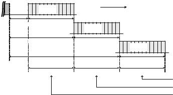
In Figure 4.5, the initial CWs do not overlap at all (in the figure, intervals X1, X2, X3), which makes the QoS differentiation between the ACs of different priorities more strictly.
However, as soon as CWs increase upon collisions, this strict priority differentiation is lost. In a scenario of multiple backoff entities contending for access, not all backoff entities increase their CWs at the same time. Thus, a backoff entity of the higher priority AC may operate with increased CWs while at the same time a medium priority backoff entity operates with CW=CWmin, for example after a successful transmission. The EDCF cannot support strict priorities between ACs, as long as increasing backoff stages lead to overlapping CWs. Figure 4.6 illustrates another possible case where the initial CWs overlap in the initial stage, making the QoS differentiation less strictly.
4.2.2.3Maximum Contention Window Size as Parameter per Access Category
The contention window increases upon unsuccessful frame exchanges, but never exceeds the value ofCWmax [AC ], which is the maximum possible value. This
parameter is defined per AC as part of the EDCF parameter set. The smaller |
|
theCWmax [AC ], the higher |
the channel access priority. However, a small |
CWmax [AC ] may increase |
the collision probability. Note that any value |
CWmin [AC ]≤CWmax [AC ] |
≤ 65535 is possible. Further, it should be high- |
lighted that the retry counters limit the number of retransmissions and can therefore limit the maximum size of the CW.
busy |
higher |
time |
|
channel |
|
||
priority AC |
|
||
AIFS[higher pr.] |
CWmin[higher pr.] |
medium |
|
|
|
|
|
|
|
priority AC |
|
AIFS[medium pr.] |
CWmin[medium pr.] |
lower |
|
|
|
|
|
|
|
|
priority AC |
|
AIFS[lower pr.] |
|
CWmin[lower pr.] |
|
X1 |
X3 |
X5 |
exclusive lower pr. exclusive medium pr. exclusive higher pr.
Figure 4.5: Non-overlapping contention windows of three Access Categories (ACs), higher, medium, lower priority.