

3.3 Medium Access Control |
35 |
3.3.2Point Coordination Function
To support time-bounded services, the IEEE 802.11 standard defines the Point Coordination Function (PCF) to let stations have priority access to the radio channel, coordinated by a station called Point Coordinator (PC). The PC typically resides in the AP.
3.3.2.1Contention Free Period and Superframes
The PCF has higher priority than the DCF, because the period during which the PCF is used is protected from the DCF access by the NAV. The time during which 802.11 stations operate is divided into repeated periods, called superframes. A superframe starts with a beacon. With an active PCF, a Contention Free Period (CFP) and a Contention Period (CP) alternate over time, where a CFP and the following CP form a superframe. During the CFP, the PCF is used for accessing the channel, while the DCF is used during the CP. It is mandatory that a superframe includes a CP of a minimum length that allows at least one MSDU Delivery under DCF. A superframe starts with a beacon frame, regardless if the PCF is active or not. The beacon frame is a management frame that maintains the synchronization of the local timers in the stations and delivers protocol related parameters, as explained earlier. The PC, which is typically co-located with the AP, generates beacon frames at regular beacon frame intervals, thus every station knows when the next beacon frame will arrive. During CFP, there is no contention among stations; instead, stations are polled. See Figure 3.13 for a typical frame exchange sequence during CFP. The PC polls a station asking for a pending frame. Because the PC itself has pending data for this station, it uses a combined data and poll frame by piggybacking the CF-Poll frame into the data frame. Therefore, no idle period longer than PIFS occurs during CFP.
|
|
P |
|
S |
|
S |
|
S |
S |
|
station 1 (PC) |
I |
beacon |
I |
DATA + |
I |
DATA + |
I |
I |
CF- |
|
F |
F |
F |
F |
F |
||||||
|
|
S |
|
S |
CF-Poll |
S |
CF-Poll |
S |
S |
End |
|
|
|
|
S |
|
|||||
station 2 |
|
|
|
|
|
DATA + |
|
CF- |
|
|
|
|
|
|
|
I |
|
|
|||
|
|
CP |
CFP |
|
|
CF-ACK |
F |
|
ACK |
CP |
|
|
|
|
|
S |
|
|
|||
|
S |
TBTT |
|
station 3 sets NAV at TBTT, update |
|
|
NAV |
|||
station 3 |
I |
|
|
|
after beacon reception |
|
|
|
||
F |
ACK |
|
|
|
|
|
|
|
reset |
|
|
S |
|
|
|
|
|
|
|
|
|
station 4 |
|
DCF data |
Station 4 is hidden to the PC, it does not set its NAV. |
|
||||||
|
transmission during |
|
This station should not be part of the BSS |
|
time |
|||||
|
|
|
|
|||||||
|
|
Contention Period |
|
coordinated by the PC (station 1). |
|
|
||||
|
|
|
|
|
NAV (timer) |
|||||
|
|
|
|
|
|
|
|
|
|
|
|
|
|
|
|
|
|
|
|
|
transmission |
Figure 3.13: Example for the PCF operation. Station 1 is the PC and polls station 2. Station 3 detects the beacon frame and updates the NAV for the whole CFP.
36 |
3. IEEE 802.11 |
The PC continues with polling other stations until the CFP expires. A CF-End control frame is transmitted by the PC as the last frame within the CFP to signal the end of the CFP.
3.3.2.2QoS Support with PCF
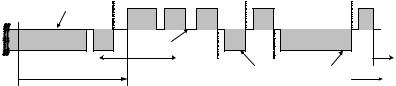
There are problems with the PCF that motivated to the current activities to enhance the protocol. Among others, the main problems are the unpredictable beacon delays and unknown transmission durations of the polled stations. See Figure 3.14 for an illustration of the problems. At TBTT, a PC schedules the beacon as the next frame to be transmitted, and the beacon can be transmitted when the channel has been determined to be idle for at least PIFS. Depending on the radio channel at this point in time, i.e., whether it is idle or busy around the TBTT, a delay of the beacon frame may occur. The time the beacon frame is delayed, i.e., the duration it is sent after the TBTT, delays the transmission of time-bounded MSDUs that have to be delivered in CFP. From the legacy 802.11 standard, stations can start their transmissions even if the MSDU Delivery cannot finish before the upcoming TBTT. This may severely affect the QoS as this introduces unpredictable time delays in each CFP. Beacon frame delays of around 4.9 ms are possible in 802.11a in the worst case.
In simulation of the PCF that have been performed, a mean beacon frame delay of up to 250 us was observed, depending on frame lengths, fragmentation, and the offered traffic (Mangold et al., 2002a). There is another problem with the PCF, the unknown transmission time of polled stations. A station that has been polled by the PC is allowed to send a single frame that may be fragmented and of arbitrary length, up to the maximum of 2304 byte (2312 byte with Wired Equivalent Privacy (WEP) encryption due to the overhead that results from the encryption). Further, different modulation and coding schemes are specified in 802.11a, thus the duration of the MSDU Delivery as response to the CF-Poll frame is not under the control of the PC. This destroys any attempt to provide QoS to other stations that are polled during the rest of the CFP.
|
previous data transmission during |
|
|
|
|
|
|
|
||
|
Contention Period transmitting across TBTT P |
S |
P |
|
S |
|
S |
|
||
station 1 (PC) |
|
I |
I |
I |
|
I |
|
I |
CF- |
|
|
F |
beacon F CF-Poll |
F CF-Poll |
|
F |
CF-Poll |
F |
|||
|
|
|
S |
S |
S |
|
S |
|
S |
End |
station 2 |
|
S |
|
|
|
S DATA + |
S |
|
|
|
DATA (MSDU) |
I |
ACK |
no response to poll, |
I |
CF- |
I |
DATA + CF-ACK |
|
||
|
|
F |
|
recover after PIFS |
F |
ACK |
F |
|
|
|
|
|
S |
|
S |
|
S |
|
|
||
|
|
|
|
|
|
|
|
|||
|
listen before talk |
CP |
CFP |
|
|
|
duration of data frames is |
CP |
||
|
|
|
|
|
|
|
|
|
||
|
|
|
|
|
|
|
|
unknown to the PC |
|
|
|
start of CFP is delayed |
|
|
|
|
|
time |
|||
TBTT
Figure 3.14: Frame exchanges with the Point Coordination Function (PCF).