

5.1 HCF Contention-based Channel Access |
67 |
Considering all these modifications, the stationary probability distribution b0,0 of an idle system is calculated as
b0,0 |
= |
|
|
|
|
|
|
|
|
|
|
|
|
|
|
|
|
|
|
|
|
|
|
|
|
|
|
|
|
|
|
|
|
|
|
|
|
|
|
|
|
|
|
|||
|
|
|
|
|
|
|
|
|
|
|
|
|
|
|
|
|
( |
|
|
|
|
) |
|
|
|
|
|
|
|
|
|
|
|
|
|
|
|
|
|
|
p = |
1 |
|
|
|
|
|
|
|
|
|
|
|
|
|
|
|
|
|
|
|
|
|
|
|
|
|
|
|
|
|
|
|
|
|
|
|
|
|
|
|
|
|
|
|
|
|
|
|
|
|||
|
|
|
|
|
|
|
|
|
|
|
|
|
|
|
|
|
|
|
|
|
|
|
|
|
|
|
|
|
|
|
|
|
|
|
|
|
|
|
|
|
|
|
|
|||
|
|
|
|
|
|
|
|
|
|
|
|
|
|
|
2 1 −p |
|
|
|
|
|
|
|
|
|
|
|
|
|
|
|
|
|
|
|
, |
|
PF [AC ], |
|
||||||||
W |
1 |
−p |
) |
m |
PF |
[ |
AC |
] |
p |
) |
m +1+W |
|
|
PF |
[ |
AC |
] |
p |
) |
m +1 |
|
|
||||||||||||||||||||||||
|
|
|
o |
( |
|
|
|
( |
|
|
|
|
|
|
|
o |
( |
|
|
|
|
|
|
|
|
|
|
m > 0 |
|
|||||||||||||||||
|
|
|
|
|
|
|
|
|
|
|
|
|
|
|
|
|
|
|
|
|
|
|
|
|
|
|
|
|
|
|
|
|
|
|
|
|
|
|
|
|||||||
|
|
|
|
|
|
|
|
|
|
|
|
|
|
|
|
|
|
|
|
|
|
|
|
|
|
|
|
|
|
|
|
|
|
|
|
|
|
|
|
|
|
1 |
|
|
|
|
|
|
|
|
|
|
|
|
|
|
|
|
|
|
|
2 (1 −p) |
|
|
|
|
|
|
|
|
|
|
|
|
|
|
|
|
|
|
|
|
|
||||||||||
|
|
|
|
|
|
|
|
|
|
|
|
|
|
|
|
|
|
|
|
|
|
|
|
|
|
|
|
|
|
|
|
|
p ≠ |
|
|
|
|
(5.3) |
||||||||
|
|
|
|
|
|
|
|
|
|
|
|
|
|
|
|
|
|
|
|
|
|
|
|
|
|
|
|
|
|
|
|
PF [AC ], |
||||||||||||||
|
|
|
|
|
|
|
|
|
|
|
|
|
|
|
|
|
|
|
|
|
|
|
|
|
|
|
|
|
|
|
|
|
|
|
|
|
|
|
|
, |
|
|||||
|
|
|
|
|
|
|
|
|
|
1 −(PF [AC ] p)m |
|
|
|
|
|
|
|
|
|
|
|
|
|
|
|
|
|
|
|
|||||||||||||||||
|
|
|
|
|
( |
|
|
) |
|
|
|
( |
|
|
|
[ |
|
|
] |
|
|
) |
m |
|
|
|
m > 0 |
|
||||||||||||||||||
|
|
|
o |
|
|
|
|
|
|
|
|
|
|
|
|
|
|
|
o |
PF |
AC |
p |
|
|
+1 |
|
|
|||||||||||||||||||
|
W |
|
1 −p |
|
|
1 −PF [AC ] p |
|
|
|
+W |
|
|
|
|
|
|
|
|
|
|
|
|
|
|||||||||||||||||||||||
|
|
|
|
|
|
|
|
|
|
|
|
|
|
|
|
|
|
|
|
|
|
|
|
|
|
|
|
|
|
|
|
|
|
|
|
|
|
|||||||||
|
|
|
|
|
|
|
|
|
|
|
|
|
|
|
|
|
|
|
2 |
|
|
|
|
|
|
|
, |
|
|
|
|
|
|
|
|
|
|
|
|
|
m = 0 |
|
||||
|
|
|
|
|
|
|
|
|
|
|
|
|
|
|
|
|
|
|
|
|
|
|
|
|
|
|
|
|
|
|
||||||||||||||||
|
|
|
|
|
|
|
|
|
|
|
|
|
2 +(1 −p) |
(W |
−1) |
|
|
|
|
|
|
|
|
|
|
|
|
|
|
|||||||||||||||||
|
|
|
|
|
|
|
|
|
|
|
|
|
|
|
|
|
|
|
|
|
|
o |
|
|
|
|
|
|
|
|
|
|
|
|
|
|
|
|
|
|
|
|
|
|
|
|
|
|
|
|
|
|
|
|
|
|
|
|
|
|
|
|
|
|
|
|
|
|
|
|
|
|
|
|
|
|
|
|
|
|
|
|
|
|
|
|
|
|
|
|
|
|
|
The probability τ that a backoff entity is transmitting in a generic slot is calculated by the summation of all stationary distributions bi ,0 , as in Bianchi’s legacy 802.11 model, given by
m |
|
1, |
|
p =1, |
|
|
|
|
1 |
|
|
τ = ∑bi ,0 |
= |
|
|
|
|
i =0 |
b0,0 |
|
|
, else. |
|
|
−p |
||||
|
|
1 |
|
||
In 802.11e, with the controlled channel access, p =1. In this case, all slots are busy at any time, and thereforeτ =1 .
All the rest of the analysis of the saturation throughput can be taken from Appendix D. Note that a generic slot is different to a backoff slot in this thesis. A generic slot may be an idle generic slot during the contention phase, or a busy generic slot during which a frame exchange is completed, or, alternatively, during which a collision occurs. It is referred to as generic slot to differentiate it from the backoff slots, because a generic slot can be a backoff slot or a busy phase with a longer duration than the backoff slot duration.
5.1.2.2Throughput Evaluation for Different EDCF Parameter Sets
The saturation throughput of a number of backoff entities that operate all according to the same AC can be approximated by modifying Bianchi’s legacy 802.11 analysis as explained in the previous Section 5.1.2.1. These approximations are evaluated in this section and compared to WARP2 simulation results. In

68 |
5. Evaluation of IEEE 802.11e with the IEEE 802.11a Physical Layer |
addition to the legacy EDCF parameters, two other EDCF parameter sets are defined in the following. One is referred to as the “higher priority AC” and the other as the “lower priority AC,” as they will allow higher and lower priority in channel access than the legacy priority, respectively. The legacy priority AC is also referred to as “medium priority AC.” The saturation throughput for the medium priority AC can be found in Appendix D, and the results for the higher and lower priority AC are shown in this section. Table 5.2 summarizes the EDCF parameter sets selected for the three ACs. The medium priority AC follows the legacy DCF protocol. The higher priority AC operates with a smaller CWmin [AC ] and a smaller PF [AC ], the lower priority AC operates with a larger CWmin [AC ] and a larger PF [AC ] than what is defined for the legacy DCF. All other EDCF parameters remain equal to the medium priority EDCF parameters.
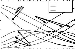
The contention window sizes for the three priorities for the first four backoff stages are presented in Figure 5.4. It can be seen that the parameter PF has a considerable impact on the resulting contention window sizes. The relative large value of AIFSN for the lower priority ( AIFSN [lower ]= 9 ) together with the larger contention window sizes will give this AC only a very limited priority in channel access.
Larger contention window sizes have also positive effects on the saturation throughput. shows the probability τ that a backoff entity transmits in a generic slot versus the number of backoff entities.
Furher, Figure 5.5 illustrates the probability p that transmission attempts at a particular slot are unsuccessful due to collision, as function of the number of backoff entities. The probabilities are shown for the three known priorities. As expected, the larger the number of backoff entities, the larger the collision probability. Further, the probability that a backoff entity is transmitting at a generic slot decreases with increasing number of backoff entities.
Table 5.2: EDCF parameter sets for the three ACs, as selected for the analysis. The TXOPlimit per AC is not used in this thesis; one value is used for all ACs. Note that the legacy DCF backoff is assumed.
AC (priority): |
higher |
medium(=legacy) |
lower |
|
|
|
|
AIFSN[AC]: |
2 |
2 |
9 |
CWmin[AC]: |
7 |
15 |
31 |
CWmax[AC]: |
1023 |
1023 |
1023 |
PF[AC]: |
24/16 |
32/16 |
40/16 |
RetryCnt[AC]: |
7 |
7 |
7 |
|
|
|
|
5.1 HCF Contention-based Channel Access |
69 |
backoff stage
|
|
|
|
|
|
|
|
|
|
|
|
|
|
|
|
|
|
|
|
|
|
|
|
|
|
|
|
|
|
|
|
|
|
|
|
|
|
|
|
|
|
|
|
|
|
|
|
|
|
|
|
|
|
|
|
|
|
|
|
|
|
|
|
|
|
|
|
|
|
|
|
|
|
|
higher pr. (802.11e) |
|
|||||||
|
|
|
|
AIFSN[AC]=9 |
|
|
|
|
|
|
|
|
|
CW[AC](stage=1) = CWmin[AC] =31 |
|
|
|
|
|
|
|
|
|
legacy pr. (802.11) |
|
|
|||||||||||||||
1 |
|
|
|
|
|
|
|
|
|
|
|
|
|
|
|
|
|
|
|
|
|
|
|
|
|
|
|
|
|
|
|
|
lower pr. (802.11e) |
|
|||||||
|
|
AIFSN[AC]=2 |
|
|
CW[AC](stage=1) = CWmin[AC] =15 |
|
|
|
|
|
|
|
|
|
|
|
|
|
|
|
|
|
|||||||||||||||||||
|
|
|
|
|
|
|
|
|
|
|
|
|
|
|
|
|
|
|
PF[AC]=[1.5(high), 2(legacy), 2.5(low)] |
|
|
|
|
|
|
|
|
|
|
|
|
||||||||||
|
|
|
|
CW[AC](stage=1) = CWmin[AC] =7 |
|
|
|
|
|
|
|
|
|
|
|
|
|
|
|
|
|
||||||||||||||||||||
|
|
AIFSN[AC]=2 |
|
|
|
|
|
|
|
|
|
|
|
|
|
|
|
|
|
|
|
|
|
|
|
|
|
|
|
|
|
|
|
|
|
|
|
|
|
|
|
|
|
|
|
|
|
|
|
|
|
|
|
|
|
|
|
|
|
|
|
|
|
|
|
|
|
|
|
|
|
|
|
|
|
|
|
|
|
|
|
|
|
|
|
|
|
AIFSN[AC]=9 |
|
|
|
|
|
|
|
|
|
|
|
|
|
|
|
|
|
|
|
|
|
|
CW[AC](stage=2) =79 |
|
|
|
|
|
|
|
|
|
|
|
|||
2 |
|
|
AIFSN[AC]=2 |
|
|
|
|
|
|
|
|
|
CW[AC](stage=2) =31 |
|
|
|
|
|
|
|
|
|
|
|
|
|
|
|
|
|
|
|
|
|
|
|
|
||||
|
|
|
|
CW[AC](stage=2) =11 |
|
|
|
|
|
|
|
|
|
|
|
|
|
|
|
|
|
|
|
|
|
|
|
|
|
|
|
|
|
|
|||||||
|
|
AIFSN[AC]=2 |
|
|
|
|
|
|
|
|
|
|
|
|
|
|
|
|
|
|
|
|
|
|
|
|
|
|
|
|
|
|
|
|
|
|
|
|
|
|
|
|
|
|
|
|
|
|
|
|
|
|
|
|
|
|
|
|
|
|
|
|
|
|
|
|
|
|
|
|
|
|
|
|
|
CW[AC](stage=3) =199 |
|
||||||
|
|
|
|
|
|
|
|
|
|
|
|
|
|
|
|
|
|
|
|
|
|
|
|
|
|
|
|
|
|
|
|
|
|
|
|
|
|||||
|
|
|
|
AIFSN[AC]=9 |
|
|
|
|
|
|
|
|
|
|
|
|
|
|
|
|
|
|
|
|
|
|
|
|
|
|
|
|
|
|
|
|
|
|
|
|
|
3 |
|
|
AIFSN[AC]=2 |
|
|
|
|
|
|
|
|
|
|
|
|
|
|
|
|
|
|
CW[AC](stage=3) =63 |
|
|
|
|
|
|
|
|
|
|
|
|
|
|
|
|
|
||
|
|
|
|
|
|
|
CW[AC](stage=3) =17 |
|
|
|
|
|
|
|
|
|
|
|
|
|
|
|
|
|
|
|
|
|
|
|
|
|
|
|
|
||||||
|
|
AIFSN[AC]=2 |
|
|
|
|
|
|
|
|
|
|
|
|
|
|
|
|
|
|
|
|
|
|
|
|
|
|
|
|
|
|
|
|
|
|
|
|
|
|
|
|
|
|
|
|
|
|
|
|
|
|
|
|
|
|
|
|
|
|
|
|
|
|
|
|
|
|
|
|
|
|
|
|
|
|
|
|
|
|
|
||
|
|
|
|
|
|
|
|
|
|
|
|
|
|
|
|
|
|
|
|
|
|
|
|
|
|
|
|
|
|
|
|
|
|
CW[AC](stage=4) =499 |
|
||||||
|
|
|
|
|
|
|
|
|
|
|
|
|
|
|
|
|
|
|
|
|
|
|
|
|
|
|
|
|
|
|
|
|
|
|
|
|
|||||
|
|
|
|
AIFSN[AC]=9 |
|
|
|
|
|
|
|
|
|
|
|
|
|
|
|
|
|
|
|
|
|
|
|
|
|
|
|
|
|
|
|
|
|
|
|
|
|
4 |
|
|
AIFSN[AC]=2 |
|
|
|
|
|
|
|
|
|
|
|
|
|
|
|
|
|
|
|
|
|
|
|
|
|
|
|
|
|
|
|
|
|
|
|
|
|
|
|
|
|
|
|
|
|
|
|
|
CW[AC](stage=4) =26 |
|
|
|
|
|
|
|
|
|
|
|
|
|
|
|
|
|
|
CW[AC](stage=4) =127 |
|
|
|
|||||||||
|
|
AIFSN[AC]=2 |
|
|
|
|
|
|
|
|
|
|
|
|
|
|
|
|
|
|
|
|
|
|
|
|
|
|
|
|
|
|
|
|
|
|
|
|
|
|
|
|
|
|
|
|
|
|
|
|
|
|
|
|
|
|
|
|
|
|
|
|
|
|
|
|
|
|
|
|
|
|
|
|
|
|
|
|
|
|
|
||
|
|
|
|
|
|
|
|
|
|
|
|
|
|
|
|
|
|
|
|
|
|
|
|||||||||||||||||||
|
|
|
|
higher backoff−stages with larger CWs are not shown here |
|
|
|
|
|
|
|
|
|
|
|
|
|
|
|
|
|
|
|
||||||||||||||||||
|
|
|
|
|
|
|
|
|
|
|
|
|
|
|
|
|
|
|
|
|
|
|
|
|
|
|
|
|
|
|
|
|
|
|
|
|
|
|
|
|
|
|
|
|
|
|
|
|
|
|
|
|
|
|
|
|
|
|
|
|
|
|
|
|
|
|
|
|
|
|
|
|
|
|
|
|
|
|
|
|
|
|
|
2 |
10 |
20 |
|
30 |
40 |
50 |
60 |
|
70 |
80 |
90 |
100 |
110 |
120 |
|
130 |
|
|
|
||||||||||||||||||||||
|
|
|
|
|
|
|
|
|
|
|
|
position and size of contention windows of three parallel backoff entities |
|
|
|
|
|
|
|
|
|
|
|
||||||||||||||||||
Figure 5.4: EDCF QoS-parameter setting for the three priorities, contention windows of the first four backoff stages.
Remarkably, with any number of backoff entities, the collision probability is higher for the higher probability AC than for the legacy and lower probability ACs, which is a result of the large contention window sizes. With a small number of backoff entities, the probability that a particular backoff entity is transmitting at a generic slot is higher for the higher priority AC than for the other ACs.
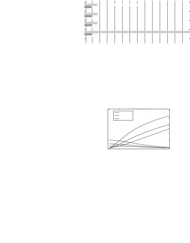
Figure 5.6 illustrates three other probabilities of the modified model as functions of the number of backoff entities. The probability that a generic slot is idle is referred to as prob(CCAidle), the probability that a collision occurs, if a generic slot is busy is referred to as prob(collision|CCAbusy) and the probability that a frame exchange is successful, provided that a generic slot is busy, is referred to as
prob(success|CCAbusy). |
|
|
|
|
|
|
1 |
|
higher pr. |
|
|
|
|
|
p = prob(collision) |
||
|
|
|
legacy pr. |
||
|
0.8 |
|
|
|
|
|
|
lower pr. |
|
|
|
p |
0.6 |
|
|
|
|
τ, |
|
|
|
|
|
|
|
|
|
|
|
prob. |
0.4 |
|
|
|
|
|
0.2 |
|
|
|
τ = prob(backoff |
|
|
|
|
entity transmits) |
|
|
0 |
|
|
|
|
|
1 |
2 |
|
10 |
50 |
number of backoff entities
Figure 5.5: Collision and transmission probability (p, τ ) for a single backoff entity in a generic slot, as functions of the number of backoff entities.
70 |
5. Evaluation of IEEE 802.11e with the IEEE 802.11a Physical Layer |
|
1 |
|
prob(CCAidle) |
higher pr. |
|
|
|
|
|
|
|||
|
|
|
legacy pr. |
|
||
|
|
|
|
|
|
|
|
0.8 |
|
|
|
lower pr. |
|
|
|
prob(collision|CCAbusy) |
|
|||
|
|
|
|
|||
prob. |
0.6 |
|
|
|
|
|
0.4 |
|
|
|
|
|
|
|
|
|
|
|
|
|
|
0.2 |
|
|
|
|
|
|
0 |
|
|
prob(success|CCAbusy) |
|
|
|
|
|
|
|
|
|
|
1 |
2 |
10 |
50 |
100 |
1000 |
|
|
|
number of backoff entities |
|
||
Figure 5.6: Probability that a generic slot is idle, busy with an collided frame, or busy with a successfully transmitted frame, as functions of the number of backoff entities.
The probabilities are defined in Appendix D.2 as PCCAidle , Pcoll , and Psuccess , respectively. The index “CCA” refers to Clear Channel Assessment (CCA), which is the
carrier sense process in the 802.11 protocol. It can be observed from Figure 5.6 that with increasing number of backoff entities the probability that a generic slot
is idle, PCCAidle , decreases, as expected. In addition, the collision probability Pcoll increases with increasing number of backoff entities, which is again an expected
result. An interesting observation is that the probability Psuccess shows maxima for all ACs, which are at different numbers of backoff entities for the different ACs.
The higher the priority, the smaller the number of backoff entities that define the unique maximum, which is an expected result.
In the next two sections, Section 5.1.2.2.1 and Section 5.1.2.2.2, the saturation throughput calculated for the two priorities “lower” and “higher” are discussed and evaluated. The figures can be compared also to the figures that show the results for the legacy AC, see Figure D.3, p. 237, and Figure D.4, p. 238.
5.1.2.2.1Lower Priority AC Saturation Throughput
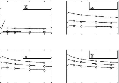
Figure 5.7 and Figure 5.8 illustrate the resulting saturation throughput obtained through simulation and analytical approximation with the modified model for the lower priority AC. Shown is the saturation throughput for different PHY modes, and a varying number of backoff entities for the frame body sizes 48, 512, 1514, and 2304 byte. The EDCF parameters as defined in Table 5.2 are used. Figure 5.7 shows the saturation throughput for scenarios without use of RTS/CTS, Figure 5.8 shows results for the same scenarios, with the use of RTS/CTS. The results show the expected characteristics.
5.1 HCF Contention-based Channel Access |
71 |
saturation thrp. (norm.)
1
0.8
0.6
0.4
0.2
0
 BPSK1/2 (6 Mbit/s)
16QAM1/2 (24 Mbit/s) 64QAM3/4 (54 Mbit/s)
thrp. increases with increasing number of backoff entities
with address 4, w/o WEP encrypt.
10 |
20 |
40 |
60 |
number of backoff entities
(a) 48 byte frame body size.
saturation thrp. (norm.)
1 BPSK1/2 (6 Mbit/s)
 16QAM1/2 (24 Mbit/s)
0.8 |
64QAM3/4 (54 Mbit/s) |
with address 4, w/o WEP encrypt.
0.6
0.4 |
|
|
|
0.2 |
|
|
|
0 |
|
|
|
10 |
20 |
40 |
60 |
|
number of backoff entities |
|
|
1 BPSK1/2 (6 Mbit/s)
 16QAM1/2 (24 Mbit/s)
(norm.) |
0.8 |
64QAM3/4 (54 Mbit/s) |
|
||
thrp. |
0.6 |
|
0.2 |
|
|
saturation |
|
|
|
0.4 |
|
|
|
with address 4, w/o WEP encrypt. |
0
10 |
20 |
40 |
60 |
|
number of backoff entities |
|
|
(c) 1514 byte frame body size.
saturation thrp. (norm.)
1
0.8
0.6
0.4
0.2
0
 BPSK1/2 (6 Mbit/s)
16QAM1/2 (24 Mbit/s) 64QAM3/4 (54 Mbit/s)
with address 4, w/o WEP encrypt.
10 |
20 |
40 |
60 |
|
number of backoff entities |
|
|
(d) 2304 byte frame body size.
lines: modified Bianchi approx.; markers: WARP2 simulation results
Figure 5.7: Normalized saturation throughput for different PHY modes, and a varying number of backoff entities, for lower priority (AC=”lower”). EDCF parameters as defined in Table 5.2. RTS/CTS are not used. The respective legacy saturation throughput is illus- trated in Appendix D.4, Figure D.3, p. 237.
The throughput increases with increasing frame body sizes. The higher the number of backoff entities, the lower the saturation throughput. The higher the PHY mode, the smaller the efficiency of the carrier sense protocol.
RTS/CTS increase the saturation throughput for long frame body sizes, but not for short frame body sizes. For small numbers of backoff entities, the saturation throughput increases with increasing number of backoff entities.
This is an expected result for the lower priority AC with its large initial contention window: as long as the collision probability is not too high, more contending backoff entities result in shorter idle phases and thus higher saturation throughput. Comparing the figures to the results of the legacy priority AC (Figure D.3, p. 237, and Figure D.4, p. 238), the saturation throughput is higher for the lower priority than for the legacy priority, which again is an effect resulting from the lower collision probability at the lower priority AC.