

5.3 Radio Resource Capture |
105 |
cess. As a result, the channel cannot be captured for time durations longer than a slot duration. In the simulation discussed in the following, a slot duration of 4 Time Units (TUs), i.e., 4.096 ms, is used. An immediate drawback of the slotting is the throughput degradation in each BSS. To mitigate this, it is here proposed to apply CFBs as explained in the next section.
5.3.4Evaluation
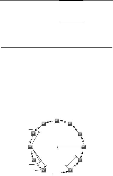
A symmetric scenario is selected to investigate the effects of slotting and CFBs in 802.11e. A circle of 12 stations forms a QBSS where all stations operate according to EDCF, see Figure 5.32. All frames are transmitted with the 12 Mbit/s PHY mode. Each station generates the same offered traffic comprising three single hop data streams, labeled as high, medium and low, according to their priorities.
By means of these streams, stations deliver MSDUs with three different priorities to one direct neighbor station, and also receive three streams from the other neighbor station. In total, 12 3 = 36 data streams are simulated. All MSDUs arrive with negative-exponentially distributed inter-arrival times.
The three priorities are always offered the same traffic. At the different backoff entities in the simulated system model, MSDUs with a size of either 600 byte or 128 byte arrive such that the queues are always full. Another traffic load is derived from an Ethernet traffic trace file that offers 1 Mbit/s with typical Ethernet frame sizes of up to 1514 byte as traffic source for each data stream.
synch. |
11 12 1 |
Access |
|
|
|
|
||
10 |
|
2 |
Point |
12 |
|
|
|
|
|
9 |
|
3 |
11 |
1 |
2 |
|
|
|
8 |
|
4 |
10 |
|
|
|
|
|
7 |
6 |
5 |
9 |
|
|
3 |
no |
|
|
|
|
8 7 |
|
|
4 |
|
|
|
|
|
6 |
5 |
update |
||
TBTT time
|
11 12 |
1 |
2 |
|
10 |
|
|
to be |
9 |
|
3 |
updated |
8 7 6 |
5 |
4 |
TBTT time
 TBTT
TBTT
time
|
beacon |
11 12 |
1 |
|
|
10 |
|
2 |
|
|
holder |
9 |
|
3 |
|
8 |
|
4 |
|
|
beacon |
7 |
6 |
5 |
|
|
|
|
|
TBTT |
time |
|
|
|
|
|
|
|
|
Access
Point
assoc. station
assoc. station
assoc. station
NEW: QBSSs apply distributed TSF as originally defined for IBSS only
NEW: co-located QBSSs accept timer information from other BSS
Figure 5.31: Two modifications in 802.11e to allow mutual synchronization for the reduction of the radio resource capture and to support multi-hop traffic.

106 |
5. Evaluation of IEEE 802.11e with the IEEE 802.11a Physical Layer |
Table 5.4 shows the relevant EDCF parameters selected for the three priority classes, summarizing the parameters that are mainly used. RTS/CTS is used for MSDUs larger than 512 byte. MSDUs are delivered in single MAC Protocol Data Units (MPDUs), i.e., MSDUs are not fragmented. The TXOPlimit is larger than the slot dwell time.
5.3.4.1Simulation Results and Discussion
The three simulated protocol configurations are the standard configuration labeled “with (resource) capture” being the protocol specified in the standard, the slotted configuration labeled “slotted,” and the slotted configuration with CFBs, labeled “bursted.” Table 5.5 presents the maximum achievable throughput for a load, where one station transmits to its neighbor and all other stations remain idle. Thus, no collisions occur at the radio channel. The results are given for the three configurations and three different types of traffic load. It can be seen that slotting reduces the throughput compared to non-slotting, whereas the CFBs has a better throughput. For shorter frame body sizes, CFB achieves even the highest throughput.
Table 5.6 shows the maximum achievable throughput in the hidden station scenario of Figure 5.32. It can be seen how severe the throughput is degraded in 802.11 by hidden stations without using slots plus CFBs.
Figure 5.33 (a) and (b) show the resulting backoff delays for the three ACs as CCDF. Here the MPDU frame body size is 600 byte. All stations together are evaluated, as the scenario is symmetric. The advantage of the slotting is clearly visible. For all ACs, the backoff times are reduced. As expected, CFBs increase the delay compared to slotting. The shapes of the curves in both figures are modulated by the slotting with a duration of 4.096 ms.
Figure 5.33 (c) and (d) show the resulting backoff delay for the Ethernet traffic trace files. Here, the positive effect of the slotting is again visible, although the advantage is not as high as before. In general, the longer the MPDUs, the more probable are channel captures, and thus, the more efficient is the slotting.
Table 5.4: Used EDCF parameters for the three ACs.
AC (priority): |
high, AC6 |
medium, AC5 |
low, AC0 |
|
|
|
|
AIFS[AC]: |
34µs |
34µs |
34µs |
CWmin[AC]: |
7 |
14 |
15 |
CWmax[AC]: |
127 |
175 |
255 |
PF[AC]: |
2 |
2 |
2 |
|
|
|
|
5.3 Radio Resource Capture |
107 |
Table 5.5: Achievable throughput (all ACs) with two isolated stations [kbit/s].
frame body size: |
600 byte |
200 byte |
Ethernet trace |
|
|
|
|
with resource capture*: |
7153.5 |
4213.7 |
=load (1Mbit/s) |
slotted: |
6831.8 |
2998.2 |
= load (1Mbit/s) |
bursted: |
6977.9 |
4987.1 |
= load (1Mbit/s) |
|
|
|
|
*) although labeled as “with capture,” captures do not occur here, as this is an isolated scenario where no hidden stations exist.
Table 5.6: Max. achievable throughput saturation throughput (all ACs) [kbit/s].
frame body size: |
600 byte |
200 byte |
Ethernet trace |
|
|
|
|
with resource capture: |
236.1 |
162.4 |
220.3 |
slotted: |
232.2 |
160.3 |
205.6 |
bursted: |
285.0 |
201.1 |
267.8 |
|
|
|
|
5.3.4.2Conclusion
The results indicate that resource channel capture by coexisting BSSs can be efficiently reduced when applying the slotting scheme as described in Benveniste (2001) together with CFBs. This modified protocol may especially have a potential for multi-hop communication and the efficient forwarding of MSDUs across multiple (Q)BSSs under QoS constraints.
|
5 |
|
|
4 |
3 |
|
|
|
|
|
|
|
|
||
|
|
PHY model: |
|||||
|
|
y path loss γ=3.3 |
|||||
|
while being |
y tx power 100mW |
|||||
6 |
y omnidirect. antennas |
|
|||||
idle, station 6 |
2 |
||||||
|
detects trans- |
|
|
|
|
|
|
|
missions from |
|
|
|
|
radius=80m |
|
|
station 7 |
|
|
|
|
||
7
station 8 receives data from station 7,
8station 9 cannot detect station 7
9 

10
1
|
|
|
m |
|
|
|
.4 |
|
|
|
1 |
|
|
|
4 |
|
|
|
|
|
|
|
||
~ |
|
|
|
12 |
|
|
|
|
|
11
Figure 5.32: Symmetric hidden station scenario. Each station detects its two neighbors. Each station carries three parallel streams of data with high, medium, low priority.

108 |
|
|
5. Evaluation of IEEE 802.11e with the IEEE 802.11a Physical Layer |
||||||||||
|
1 |
|
|
|
with capture |
|
|
1 |
|
|
with capture |
|
|
|
|
|
|
|
|
|
|
|
|
|
|||
|
|
|
|
|
4.096ms slotting |
|
|
|
|
4.096ms slotting, CFBs |
|||
(CDF) |
0.1 |
|
|
|
low priority |
(CDF) |
0.1 |
|
|
|
low priority |
||
|
|
|
|
|
|
|
|
|
|
||||
Prob(delay>x) |
0.01 |
high priority |
|
|
|
|
Prob(delay>x) |
0.01 |
high priority |
|
|
|
|
|
|
|
|
|
|
|
|
|
|
|
|
||
|
0.001 |
medium priority |
|
|
|
|
0.001 |
medium priority |
|
|
|
||
|
5 |
10 |
15 |
20 |
25 |
|
5 |
10 |
15 |
20 |
25 |
||
|
0 |
|
0 |
||||||||||
|
|
|
x=backoff delay [ms] |
|
|
|
|
x=backoff delay [ms] |
|
|
|||
(a) “Slotted”, 600 byte frame body size.
(b) “Bursted”, with CFBs, 600 byte frame body size.
|
1 |
Ethernet trace |
|
with capture |
|
|
1 |
Ethernet trace |
with capture |
|
|||
|
|
|
|
|
|
|
|||||||
|
|
|
|
|
4.096ms slotting |
|
|
|
|
4.096ms slotting, CFBs |
|||
(CDF) |
|
|
|
|
low priority |
(CDF) |
|
|
|
|
low priority |
||
0.1 |
|
|
|
|
|
0.1 |
|
|
|
|
|
||
Prob(delay>x) |
0.01 |
high priority |
|
|
|
|
Prob(delay>x) |
0.01 |
high priority |
|
|
|
|
|
|
|
|
|
|
|
|
|
|
|
|
||
|
|
medium priority |
|
|
|
|
|
medium priority |
|
|
|
||
|
0.001 |
5 |
10 |
15 |
20 |
25 |
|
0.001 |
5 |
10 |
15 |
20 |
25 |
|
0 |
|
0 |
||||||||||
|
|
|
x=backoff delay [ms] |
|
|
|
|
x=backoff delay [ms] |
|
|
|||
(c) “Slotted”, Ethernet trace. |
(d) “Bursted”, with CFBs, Ethernet trace. |
Figure 5.33: Backoff delays for different offered traffics, standard 802.11 (“with capture”), with slotting, and with slotting incl. CFBs.
5.4HCF Controlled Channel Access, Coexistence of Overlapping QBSSs
The controlled channel access of the HCF provides the highest possible priority in channel access to a backoff entity. Usually, the HC makes use of the controlled channel access by periodically polling various backoff entities during the contention period. A time interval during which the channel is allocated with the controlled channel access is referred to as Controlled Access Phase (CAP).
At any time during the contention free period (which is optional) or during the contention period, the HC can allocate a CAP, as soon as the channel is idle for a duration of PIFS. This works sufficiently only as long as one HC operates at the channel. When two or more HCs of overlapping QBSSs operate at the same time in a coexistence scenario, the controlled channel access cannot provide the required QoS, as will be discussed in the following.