

CSE477
VLSI Digital Circuits
Fall 2001
Lecture 13 &14: Dynamic CMOS
www.cse.psu.edu/~cg477
[Adapted in part from Rabaey’s Digital Integrated Circuits, ©Prentice Hall, 1995]
CSE477 L# topic.1 |
Irwin&Vijay, PSU, 2001 |

Review: Designing Fast CMOS Gates
qTransistor sizing
qProgressive transistor sizing
l fet closest to the output is smallest of series fets
q Transistor ordering
l put latest arriving signal closest to the output
q Logic structure reordering
l replace large fan-in gates with smaller fan-in gate network
q Buffer (inverter) insertion
lseparate large fan-in from large CL with buffers
luses buffers so no more than four t-gates in series
CSE477 L# topic.2 |
Irwin&Vijay, PSU, 2001 |

Review: Designing Low Power CMOS Gates
P = CL VDD2 f0→1 + tscVDD Ipeak f0→1 + VDD Ileakage
q Reduce switching (supply) voltage
lquadratic effect -> dramatic savings
lnegative effect on performance
qReduce load capacitance
qReduce switching frequency
lswitching activity and glitching
-delay balancing - equalizing timing paths through logic
-logic topology alternatives
-input ordering - postpone signals with high transition rates
lclock rate
qReduce short circuit currents (slope engineering)
qReduce leakage currents
CSE477 L# topic.3 |
Irwin&Vijay, PSU, 2001 |

In addition, the Eclipse Group’s engineers were finding plenty of bugs in the logic of their design. … So Rasala’s schedules slipped and slipped, and slipped again. “The way to stay on schedule,” he said, “is to make another one.”
The Soul of a New Machine, Kidder, pg. 246
CSE477 L# topic.4 |
Irwin&Vijay, PSU, 2001 |

Dynamic CMOS
qIn static circuits at every point in time (except when
switching) the output is connected to either GND or VDD via a low resistance path.
l fan-in of N requires 2N devices
qDynamic circuits rely on the temporary storage of signal values on the capacitance of high impedance nodes.
lrequires on N + 2 transistors
ltakes a sequence of precharge and conditional evaluation phases to realize logic functions
CSE477 L# topic.5 |
Irwin&Vijay, PSU, 2001 |
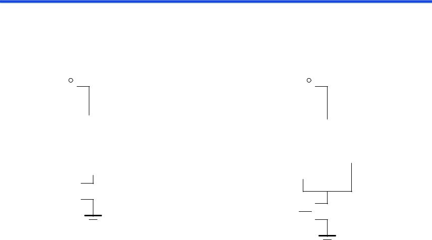
Dynamic Gate
|
|
|
|
|
|
|
|
|
|
|
|
|
|
|
|
|
CLK |
|
|
|
|
|
|
|
|
|
|
|
|
|||
CLK |
|
|
|
|
|
Mp |
|
|
|
|
|
Mp |
||||||||||||||||||||
|
|
|
|
|
|
|
|
|
||||||||||||||||||||||||
|
|
|
|
|||||||||||||||||||||||||||||
|
|
|
|
|
|
|
|
|
|
|
|
|
|
|
|
Out |
|
|
|
|
|
|
|
|
|
|
|
|
|
|
|
Out |
|
|
|
|
|
|
|
|
|
|
|
|
|
|
|
|
|
|
|
|
|
|
|
|
|
|
|
|
|
|
|
||
|
|
|
|
|
|
|
|
|
|
|
|
|
|
|
|
|||||||||||||||||
In1 |
|
|
|
|
|
|
|
|
|
|
|
|
CL |
A |
|
|
|
|
|
|
|
|
|
|
|
|
|
|
|
|||
|
|
|
|
|
|
|
|
|
|
|
|
|
|
|
|
|
|
|
|
|
|
|
|
|
|
|||||||
|
|
|
|
|
|
|
|
|
|
|
|
|
|
|
|
|
|
|
|
|
|
|
|
|
|
|
|
|
||||
|
|
|
|
|
|
|
|
|
|
|
|
|
|
|
|
|
|
|
|
|
|
|
|
|
|
|
|
|
||||
|
|
|
|
|
|
|
|
|
|
|
|
|
|
|
|
|
|
|
|
|
|
|
||||||||||
|
|
|
|
|
|
|
|
|
|
|
|
|
|
|
|
|
|
|
|
|
|
|
|
|
|
|
|
|
||||
In2 |
|
|
|
|
|
PDN |
|
|
|
|
|
|
|
|
|
|
|
|
|
|
C |
|||||||||||
|
|
|
|
|
|
|
|
|
|
|
|
|
||||||||||||||||||||
|
|
|
|
|
|
|
|
|
|
|
|
|
|
|
|
|
|
|
|
|
|
|
|
|||||||||
|
|
|
|
|
|
|
|
|
|
|
|
|
|
|
|
|
|
|
|
|
|
|
|
|
|
|||||||
In3 |
|
|
|
|
|
|
|
|
|
|
|
|
|
|
|
|
|
|
|
|
|
|
|
|
|
|
|
|
|
|
|
|
|
|
|
|
|
|
|
|
|
|
|
|
|
|
|
|
|
|
|
|
|
|
|
|
|
|
|
|
|
|
|
||
|
|
|
|
|
|
|
|
|
|
|
|
|
|
|
|
B |
|
|
|
|
|
|
|
|
|
|
|
|
|
|
||
|
|
|
|
|
|
|
|
|
|
|
|
|
|
|
|
|
|
|
|
|
|
|
|
|||||||||
CLK
 Me
Me
CLK 
 Me
Me
Two phase operation
Precharge (CLK = 0)
Evaluate (CLK = 1)
CSE477 L# topic.6 |
Irwin&Vijay, PSU, 2001 |
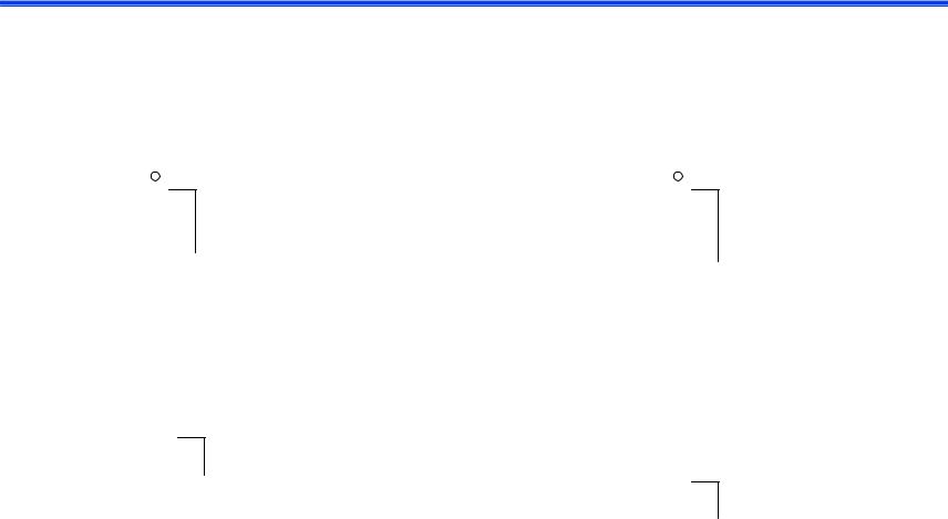
Dynamic Gate
|
|
|
|
|
|
|
|
|
|
|
|
|
|
|
|
|
|
|
CLK |
|
|
|
|
|
|
|
|
|
off |
|
|
|
||||
|
|
|
|
|
|
|
|
|
|
|
|
|
|
|
|
|
|
|
|
|
|
|
|
|
|
|
|
|
||||||||
|
|
|
|
|
|
Mp |
|
|
|
|
|
Mp on |
|
|
|
|||||||||||||||||||||
CLK |
|
|
|
|
|
|
|
1 |
||||||||||||||||||||||||||||
|
|
|
|
|
|
|
|
|
|
|
|
|||||||||||||||||||||||||
|
|
|
|
|
|
|
|
|
|
|
|
|
|
|
|
|
|
Out |
|
|
|
|
|
|
|
|
|
|
|
|
|
|
|
|
|
Out |
|
|
|
|
|
|
|
|
|
|
|
|
|
|
|
|
|
|
|
|
|
|
|
|
|
|
|
|
|
|
|
|
|
|
|
||
|
|
|
|
|
|
|
|
|
|
|
|
|
|
|
|
|
|
|
|
|
|
|
|
|
|
|
|
|
|
|
|
|
||||
In1 |
|
|
|
|
|
|
|
|
|
|
|
|
|
|
|
|
CL |
A |
|
|
|
|
|
|
|
|
|
|
|
|
|
|
|
|
!((A&B)|C) |
|
|
|
|
|
|
|
|
|
|
|
|
|
|
|
|
|
|
|
|
|
|
|
|
|
|
|
|
|
|
|
|||||||
|
|
|
|
|
|
|
|
|
|
|
|
|
|
|
|
|
|
|
|
|
|
|
|
|
|
|
|
|
|
|
|
|
||||
|
|
|
|
|
|
|
|
|
|
|
|
|
|
|
|
|
|
|
|
|
|
|
|
|
|
|
|
|
|
|
|
|
||||
|
|
|
|
|
|
|
|
|
|
|
|
|
|
|
|
|
|
|
|
|
|
|
|
|
|
|
||||||||||
|
|
|
|
|
|
|
|
|
|
|
|
|
|
|
|
|
|
|
|
|
|
|
|
|
|
|
|
|
|
|
|
|
||||
In2 |
|
|
|
|
PDN |
|
|
|
|
|
|
|
|
|
|
|
|
|
|
|
|
|
|
|
|
C |
||||||||||
|
|
|
|
|
|
|
|
|
|
|
|
|
|
|
|
|
|
|
|
|
||||||||||||||||
|
|
|
|
|
|
|
|
|
|
|
|
|
|
|
|
|
|
|
|
|
|
|
|
|
|
|
||||||||||
|
|
|
|
|
|
|
|
|
|
|
|
|
|
|
|
|
|
|
|
|
|
|
|
|
|
|
||||||||||
In3 |
|
|
|
|
|
|
|
|
|
|
|
|
|
|
|
|
|
|
|
|
|
|
|
|
|
|
|
|
|
|
|
|
|
|
|
|
|
|
|
|
|
|
|
|
|
|
|
|
|
|
|
|
|
|
|
|
|
|
|
|
|
|
|
|
|
|
|
|
|
|
|
||
|
|
|
|
|
|
|
|
|
|
|
|
|
|
|
|
|
|
B |
|
|
|
|
|
|
|
|
|
|
|
|
|
|
|
|
||
|
|
|
|
|
|
|
|
|
|
|
|
|
|
|
|
|
|
|
|
|
|
|
|
|
|
|
|
|
|
|
||||||
|
|
|
|
|
|
|
|
|
|
|
|
|
|
|
|
|
|
|
|
|
|
|
|
|
|
|
|
|
|
|
|
|
|
|
|
|
CLK |
|
|
|
|
Me |
|
|
|
|
|
|
|
|
|
|
|
|
|
|
|
|
|
|
|||||||||||||
|
|
|
|
|
|
|
|
|
|
|
|
|
|
|
|
|
off |
|
|
|
||||||||||||||||
|
|
|
|
|
|
|
|
|
|
|
|
|
|
|
|
|
|
|
|
|||||||||||||||||
|
|
|
|
|
|
|
|
|
|
|
|
|
|
|
|
|
|
|
|
|
|
|
|
|
|
|
|
|
|
|
|
|
|
|
||
|
|
|
|
|
|
|
|
|
|
|
|
|
|
|
|
|
|
|
|
CLK |
|
|
|
|
Me on |
|
|
|
||||||||
|
|
|
|
|
|
|
|
|
|
|
|
|
|
|
|
|
|
|
|
|
|
|
|
|
|
|
||||||||||
|
|
|
|
|
|
|
|
|
|
|
|
|
|
|
|
|
|
|
|
|
|
|||||||||||||||
Two phase operation |
|
|
|
|
|
|
||||||||||||||||||||||||||||||
|
|
|
|
|
|
|
|
|
|
|
|
|
|
|
|
|
|
|||||||||||||||||||
|
|
|
|
|
|
|
|
|
|
|
|
|
|
|
|
|
|
|||||||||||||||||||
|
|
|
Precharge (CLK = 0) |
|
|
|
|
|
|
|
|
|
|
|
|
|
|
|
|
|
|
|||||||||||||||
|
|
|
Evaluate (CLK = 1) |
|
|
|
|
|
|
|
|
|
|
|
|
|
|
|
|
|
|
|||||||||||||||
CSE477 L# topic.7 |
Irwin&Vijay, PSU, 2001 |

Conditions on Output
qOnce the output of a dynamic gate is discharged, it cannot be charged again until the next precharge operation.
qInputs to the gate can make at most one transition during evaluation.
qOutput can be in the high impedance state during and after evaluation (PDN off), state is stored on CL
CSE477 L# topic.8 |
Irwin&Vijay, PSU, 2001 |

Properties of Dynamic Gates
q Logic function is implemented by the PDN only
lnumber of transistors is N + 2 (versus 2N for static complementary CMOS)
lshould be smaller in area than static complementary CMOS
qFull swing outputs (VOL = GND and VOH = VDD)
qNonratioed - sizing of the devices is not important for proper functioning
qFaster switching speeds
lreduced load capacitance due to lower number of transistors per gate (Cint)
lreduced load capacitance due to smaller fan-out (Cext)
lno Isc, so all the current provided by PDN goes into discharging CL
CSE477 L# topic.9 |
Irwin&Vijay, PSU, 2001 |

Properties of Dynamic Gates, con’t
q Power dissipation should be better
l consumes only dynamic power – no short circuit power consumption since the pull-up path is not on when evaluating
l lower CL
l by construction can have at most one transition per cycle – no glitching
q But power dissipation can be significantly higher due to
l higher transition probabilities l extra load on CLK
q PDN starts to work as soon as the input signals exceed VTn, so set VM, VIH and VIL equal to VTn
l low noise margin (NML)
q Needs a precharge clock
CSE477 L# topic.10 |
Irwin&Vijay, PSU, 2001 |