


![]()


Description Styles
• Design Hierarchy
The principal design entity in the Verilog language is the module.
• Structural Descriptions
The structural elements of a Verilog structural description are generic logic gates, library-specific components, and user-defined components connected by wires.
A Verilog structural description can define a range of hierarchical and gate-level constructs, including module definitions, module instantiations, and netlist connections.
• Functional Descriptions
The functional elements of a Verilog description are function declarations, task statements, and always blocks. These elements describe the function of the circuit but do not describe its physical makeup or layout.
• Mixing Structural and Functional Descriptions
• Register Selection
The clocking scheme and the placement of registers are important architectural factors.
• Asynchronous Designs
Asynchronous designs use multiple or gated clocks
Structural Descriptions
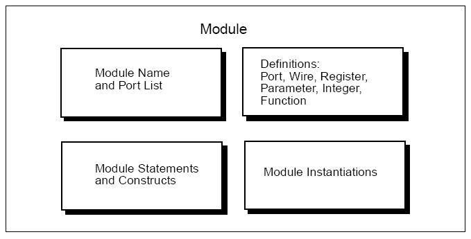
• Modules
Structural Parts of a Module
`include "<file_name>"
Ex: `include "paramters.v"
• Macromodules
The macromodule construct makes simulation more efficient, by merging the macromodule definition with the definition of the calling (parent) module.
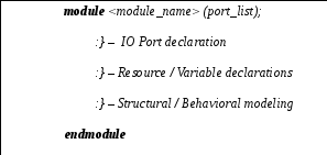
• Port Declarations
module <module_name> ( port_list );
• input declarations, output declarations, inout declarations
input, output, inout, inout reg, output reg
module ex1( a, b, c, d, e, f, g );
input a, b;
inout c;
input [3:0] d;
inout reg [15:0] e; (!!!)
output f;
output reg [15:0] g;
endmodule
The syntax for a range specification is [msb : lsb]
• Module Statements and Constructs
• parameter declarations
parameter <name> = <value>;
parameter TRUE=1, FALSE=0;
parameter [1:0] S0=3, S1=1, S2=0, S3=2;
Structural Data Types
Verilog structural data types include wire, wand, wor, tri, supply0, and supply1.
-
wire
• By connecting the wire to the output of a gate or module
• By assigning a value to the wire in a continuous assignment
wire {[msb : lsb]} <name>;
wire signed {[msb : lsb]} <name>;
<variable> signed <net data type> signed
-
wand (wired-AND), wor (wired-OR), tri
module wand_test(a, b, c, d, e);
input a, b;
output c, d, e;
wand c;
wor d;
tri e;
assign c = a;
assign c = b;
assign d = a;
assign d = b;
assign e = a; (!!!)
assign e = b; (!!!)
endmodule
The value of c is determined by the logical AND of a and b.
The value of d is determined by the logical OR of a and b.
All variables that drive the tri must have a value of Z (high-impedance), except one.
-
supply0, supply1
The supply0 and supply1 data types define wires tied to logic 0 (ground) and logic 1 (power).
supply0 gnd;
supply1 power;
• reg declarations
A reg represents a variable in Verilog. A reg can be a 1-bit quantity or
a vector of bits.
reg <name>;
reg [15:0] <name>;
reg signed [15:0] <name>;
reg <name> = 1'b0;
reg signed [15:0] <name> = 16'h0000;
reg <name> [3:0];
reg [3:0] <name> [9:0];
• Continuous assignments
wire a; //declare
assign a = b & c; //assign
wire a = b & c; //declare and assign
The left side of a continuous assignment can be
• A wire, wand, wor, or tri
• One or more bits selected from a vector (Ex: a[3:0])
• A concatenation of any of these (Ex: {a,b,c[1:0]})
!!! You cannot assign a value to a reg in a continuous assignment.
• Module instantiations
module_name instance_name1 ( terminal, terminal, ...),
instance_name2 ( terminal, terminal, ...);
module SEQ(BUS0,BUS1,OUT); //description of module SEQ
input BUS0, BUS1;
output OUT;
endmodule
module top( D0, D1, D2, D3, OUT0, OUT1 );
input D0, D1, D2, D3;
output OUT0, OUT1;
SEQ SEQ_1 (D0, D1, OUT0), //instantiations of module SEQ
SEQ_2 (.OUT(OUT1), .BUS1(D3), .BUS0(D2));
endmodule
Module instantiations can use either named or positional notation to specify the terminal connections.
-
Parameterized Designs
module_name #( parameter_value, parameter_value,...)
instance_name ( terminal_list)
module foo (a,b,c);
parameter width = 8;
input [width-1:0] a,b;
output [width-1:0] c;
assign c = a & b;
endmodule
• Gate instantiations
• and, nand, or, nor, xor, xnor, buf, not, tran
buf bufa (buf_out, e);
and and2 (and_out, a, b);
and and5 (and_out, a, b, c, d, e);
Three-State Buffer Instantiation
• bufif0 (active-low enable line)
• bufif1 (active-high enable line)
• notif0 (active-low enable line, output inverted)
• notif1 (active-high enable line, output inverted)
• The first terminal connects to the output of the gate.
• The second terminal connects to the input of the gate.
• The third terminal connects to the control line.