

Fundamentals Of Wireless Communication
.pdf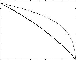

240 |
Multiuser capacity and opportunistic communication |
of interference to the weak user. In contrast, an orthogonal scheme has to allocate a significant fraction of the degrees of freedom to the weak user to achieve near single-user performance, and this causes a large degradation in the performance of the strong user.
So far we have considered a specific signaling scheme: linear superposition of the signals of the two users to form the transmit signal (cf. (6.19)). With this specific encoding method, the SIC decoding procedure is optimal. However, one can show that this scheme in fact achieves the capacity and the boundary of the capacity region of the downlink AWGN channel is given by (6.22) (Exercise 6.26).
While we have restricted ourselves to two users in the presentation, these results have natural extensions to the general K-user downlink channel. In the symmetric case hk = h for all k, the capacity region is given by the single constraint
k=1 |
k |
+ N0 |
|
|
|
|
|
|
P h 2 |
|
|
K |
R < log |
1 |
|
(6.24) |
|
|
|
||||
In general with the ordering h1 ≤ h2 ≤ · · · ≤ hK , the boundary of the capacity region of the downlink AWGN channel is given by the parameterized rate tuple
|
|
= |
|
+ N0 |
+ |
j=k+1 |
Pj |
hk 2 |
|
= |
|
|
R |
k |
|
log 1 |
|
|
Pk hk 2 |
|
k |
|
1 K |
(6.25) |
|
|
|
|
|
|
K |
|
|
|
|
|
|
|
where P = Kk=1 Pk is the power split among the users. Each rate tuple on the boundary, as in (6.25), is achieved by superposition coding.
Since we have a full characterization of the tradeoff between the rates at which users can be reliably communicated to, we can easily derive specific scalar performance measures. In particular, we focused on sum capacity in the uplink analysis; to achieve the sum capacity we required all the users to transmit simultaneously (using the SIC receiver to decode the data). In contrast, we see from (6.25) that the sum capacity of the downlink is achieved by transmitting to a single user, the user with the highest SNR.
Summary 6.1 Uplink and downlink AWGN capacity
Uplink:
|
K |
|
y m = |
|
|
xk m + w m |
(6.26) |
k=1
with user k having power constraint Pk.

241 6.2 Downlink AWGN channel
Achievable rates satisfy: |
|
|
|
|
||
|
|
k |
Pk |
|
|
|
k Rk ≤ log 1 + |
N0 |
|
for all |
1 K |
(6.27) |
|
The K! corner points are achieved by SIC, one corner point for each |
||||||
cancellation order. They all achieve the same optimal sum rate. |
|
|||||
A natural ordering would be to decode starting from the strongest user |
||||||
first and move towards the weakest user. |
|
|
||||
Downlink: |
|
|
|
|
|
|
|
ykm = hkx m + wkm |
k = 1 K |
(6.28) |
|||
with h1 ≤ h2 ≤ ≤ hK .
The boundary of the capacity region is given by the rate tuples: |
|
|||||||||||
|
|
= |
|
+ N0 |
+ j=k+1 Pj hk 2 |
|
|
= |
|
|
||
R |
k |
|
log 1 |
|
|
Pk hk 2 |
|
|
k |
|
1 K |
(6.29) |
|
|
|
|
|
K |
|
|
|
|
|
||
for all possible splits P = k Pk of the total power at the base-station.
The optimal points are achieved by superposition coding at the transmitter and SIC at each of the receivers.
The cancellation order at every receiver is always to decode the weaker users before decoding its own data.
Discussion 6.1 SIC: implementation issues
We have seen that successive interference cancellation plays an important role in achieving the capacities of both the uplink and the downlink channels. In contrast to the receivers for the multiple access systems in Chapter 4, SIC is a multiuser receiver. Here we discuss several potential practical issues in using SIC in a wireless system.
•Complexity scaling with the number of users In the uplink, the basestation has to decode the signals of every user in the cell, whether it uses the conventional single-user receiver or the SIC. In the downlink, on the other hand, the use of SIC at the mobile means that it now has to decode information intended for some of the other users, something it would not be doing in a conventional system. Then the complexity at each mobile scales with the number of users in the cell; this is not very acceptable. However, we have seen that superposition coding in conjunction with

242 |
Multiuser capacity and opportunistic communication |
SIC has the largest performance gain when the users have very disparate channels from the base-station. Due to the spatial geometry, typically there are only a few users close to the base-station while most of the users are near the edge of the cell. This suggests a practical way of limiting complexity: break the users in the cell into groups, with each group containing a small number of users with disparate channels. Within each group, superposition coding/SIC is performed, and across the groups, transmissions are kept orthogonal. This should capture a significant part of the performance gain.
•Error propagation Capacity analysis assumes error-free decoding but of course, with actual codes, errors are made. Once an error occurs for
a user, all the users later in the SIC decoding order will very likely be decoded incorrectly. Exercise 6.12 shows that if pei is the probability of decoding the ith user incorrectly, assuming that all the previous users are decoded correctly, then the actual error probability for the kth user under SIC is at most
k |
|
|
|
pei |
(6.30) |
i=1
So, if all the users are coded with the same target error probability assuming no propagation, the effect of error propagation degrades the error probability by a factor of at most the number of users K. If K is reasonably small, this effect can easily be compensated by using a slightly stronger code (by, say, increasing the block length by a small amount).
•Imperfect channel estimates To remove the effect of a user from the aggregate received signal, its contribution must be reconstructed from the decoded information. In a wireless multipath channel, this contribution depends also on the impulse response of the channel. Imperfect estimate of the channel will lead to residual cancellation
errors. One concern is that, if the received powers of the users are very disparate (as in the example in Figure 6.3 where they differ by 20 dB), then the residual error from cancelling the stronger user can still swamp the weaker user’s signal. On the other hand, it is also easier to get an accurate channel estimate when the user is strong. It turns out that these two effects compensate each other and the effect of residual errors does not grow with the power disparity (Exercise 6.13).
•Analog-to-digital quantization error When the received powers of the users are very disparate, the analog-to-digital (A/D) converter needs to have a very large dynamic range, and at the same time, enough resolution to quantize accurately the contribution from the weak signal.
For example, if the power disparity is 20 dB, even 1-bit accuracy for the weak signal would require an 8-bit A/D converter. This may well pose an implementation constraint on how much gain SIC can offer.

243 |
6.3 Uplink fading channel |
6.3 Uplink fading channel
Let us now include fading. Consider the complex baseband representation of the uplink flat fading channel with K users:
|
K |
|
y m = |
|
|
hk m xk m + w m |
(6.31) |
k=1
where hk m m is the fading process of user k. We assume that the fading processes of different users are independent of each other and hk m 2 = 1. Here, we focus on the symmetric case when each user is subject to the same average power constraint, P, and the fading processes are identically distributed. In this situation, the sum and the symmetric capacities are the key performance measures. We will see later in Section 6.7 how the insights obtained from this idealistic symmetric case can be applied to more realistic asymmetric situations. To understand the effect of the channel fluctuations, we make the simplifying assumption that the base-station (receiver) can perfectly track the fading processes of all the users.
6.3.1 Slow fading channel
Let us start with the slow fading situation where the time-scale of communication is short relative to the coherence time interval for all the users, i.e., hk m = hk for all m. Suppose the users are transmitting at the same rate R bits/s/Hz. Conditioned on each realization of the channels h1 hK, we have the standard uplink AWGN channel with received SNR of user k equal to hk 2P/N0. If the symmetric capacity of this uplink AWGN channel is less than R, then the base-station can never recover all of the users’ information accurately; this results in outage. From the expression for the capacity region of the general K-user uplink AWGN channel (cf. (6.10)), the probability of the outage event can be written as
|
|
hk 2 |
< R for some 1 K |
|
poutul |
= log 1 + SNR k |
|
||
|
|
|
|
|
(6.32)
Here denotes the cardinality of the set and SNR = P/N0. The corresponding -outage symmetric capacity, Csym, is then the largest rate R such that the outage probability in (6.32) is smaller than or equal to .
In Section 5.4.1, we have analyzed the behavior of the outage capacity, C SNR , of the point-to-point slow fading channel. Since this corresponds to the performance of just a single user, it is equal to Csym with K = 1. With more than one user, Csym is only smaller: now each user has to deal not only
244 |
Multiuser capacity and opportunistic communication |
with a random channel realization but also inter-user interference. Orthogonal multiple access is designed to completely eliminate inter-user interference at the cost of lesser (by a factor of 1/K) degrees of freedom to each user (but the SNR is boosted by a factor of K). Since the users experience independent fading, an individual outage probability of for each user translates into
1 − 1 − K ≈ K
outage probability when we require each user’s information to be successfully decoded. We conclude that the largest symmetric -outage rate with orthogonal multiple access is equal to
C/K KSNR |
(6.33) |
|
|
|
|
|
||
K |
|
|
How much improved are the outage performances of more sophisticated multiple access schemes, as compared to orthogonal multiple access?
At low SNRs, the outage performance for any K is just as poor as the point-to-point case (with the outage probability, pout, in (5.54)): indeed, at
low SNRs we can approximate (6.32) as |
|
|
|
|||||
ul |
|
h |
2P |
|
|
|
|
1 K |
|
k |
|
|
|
|
|||
pout ≈ |
|
N0 |
< R loge 2 for some k |
|
||||
≈ Kpout |
|
|
|
|
(6.34) |
|||
So we can write |
|
|
|
|
|
|
|
|
|
|
|
Csym ≈ C/K SNR |
|
|
|
||
|
|
|
|
|
|
|
|
|
|
|
|
|
≈ F−1 1 − |
|
Cawgn |
|
(6.35) |
|
|
|
|
K |
|
|||
Here we used the approximation for C at low SNR in (5.61). Since Cawgn is linear in SNR at low SNR,
Csym ≈ |
C |
/K |
KSNR |
|
(6.36) |
|
|
||||
|
|
K |
the same performance as orthogonal multiple access (cf. (6.33)).
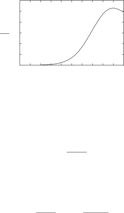
The analysis at high SNR is more involved, so to get a feel for the role of inter-user interference on the outage performance of optimal multiple access schemes, we plot Csym for K = 2 users as compared to C , for Rayleigh fading, in Figure 6.10. As SNR increases, the ratio of Csym to C increases; thus the effect of the inter-user interference is becoming smaller. However, as SNR becomes very large, the ratio starts to decrease; the inter-user interference begins to dominate. In fact, at very large SNRs the ratio drops back to 1/K (Exercise 6.14). We will obtain a deeper understanding of this behavior when we study outage in the uplink with multiple antennas in Section 10.1.4.
246 |
Multiuser capacity and opportunistic communication |
Hence, without channel state information at the transmitter, fading always hurts, just as in the point-to-point case. However, when the number of users becomes large, 1/K · Kk=1 hk 2 → 1 with probability 1, and the penalty due to fading vanishes.
To understand why the effect of fading goes away as the number of users grows, let us focus on a specific decoding strategy to achieve the sum capacity. With each user spreading their information on the entire bandwidth simultaneously, the successive interference cancellation (SIC) receiver, which is optimal for the uplink AWGN channel, is also optimal for the uplink fading channel. Consider the kth stage of the cancellation procedure, where user k is being decoded and users k+1 K are not canceled. The effective channel that user k sees is
|
|
|
|
|
|
K |
|
|
|
|
|
|
|
= |
hi m xi m + w m |
|
|||
y m = hk m xk m + |
k+1 |
(6.38) |
|||||||
|
|
|
|
|
i |
|
|
|
|
The rate that user k gets is |
|
+ i=k+1 hi 2P + N0 |
|
|
|||||
|
= |
|
|
|
|||||
Rk |
|
log |
1 |
|
|
|
hk 2P |
|
(6.39) |
|
|
|
K |
|
|||||
Since there are many users sharing the spectrum, the SINR for user k is low. Thus, the capacity penalty due to the fading of user k is small (cf. (5.92)). Moreover, there is also averaging among the interferers. Thus, the effect of the fading of the interferers also vanishes. More precisely,
Rk |
|
|
|
|
|
hk 2P |
|
|
|
log2 e |
|||||
|
|
K |
|
|
+ |
|
|||||||||
|
≈ |
|
|
= hk |
2P |
2P |
N0 |
|
|||||||
|
|
|
|
|
i k+1 |
hi |
|
|
|||||||
|
≈ |
|
|
|
|
|
log2 e |
||||||||
|
K |
k P |
+ |
N0 |
|||||||||||
|
|
|
|
|
|
− |
|
|
|
|
|
|
|||
|
= |
|
|
|
|
P |
|
|
|
log2 e |
|
||||
|
K − k P + N0 |
|
|
||||||||||||
which is the rate that user k would have got in the (unfaded) AWGN channel. The first approximation comes from the linearity of log 1 + SNR for small SNR, and the second approximation comes from the law of large numbers.
In the AWGN case, the sum capacity can be achieved by an orthogonal multiple access scheme which gives a fraction, 1/K, of the total degrees of freedom to each user. How about the fading case? The sum rate achieved by
this orthogonal scheme is |
|
|
P |
= log 1 + |
|
P |
|
|||||
k=1 |
K log 1 + |
|
h |
k |
K hk |
(6.40) |
||||||
K |
1 |
|
K |
2 |
|
|
|
2 |
|
|
|
|
|
|
|
|
|
|
|
|
|
|
|
|
|
|
|
|
|
N0 |
|
|
|
N0 |
|
|
|
|
