


Chapter 4 — Antenna Hacks 79
Using a Signal Repeater
Another way to bring a signal indoors — for example, into an office building in which you want to set up a PC time sync system on each floor — is to use a GPS signal repeater.
GPS signal repeaters are also great idea on bigger yachts and boats too.
For specific information on splitters and repeaters, helpful websites include the following:
Coverage Solutions: www.coveragesolutions.net/gps.htm
GPS Source: www.gpssource.com
A GPS repeater kit usually consists of an amplifier with a power supply and a passive antenna assembled on a mount for easy roof installation. The input from an active GPS roof antenna is amplified and retransmitted into the building.
These kits usually have an indoor range of about 250 feet (80 meters) and are easy to fit.
Installing these kits is easy because they are packaged with everything you need. All the parts are properly weatherproofed and all the attenuation measurements are predetermined. The GPS repeater kits normally include a preassembled pedestal GPS amplifier antenna assembly. This is mounted indoors in the room or building into which you want to bring a GPS signal. The best placement is in a corner, about 8 to 30 feet (2.5 to 9 meters) high. This is then connected via the GPS cable to the GPS roof antenna, which has been positioned in a suitable spot. The amplifier antenna assembly is then used to retransmit the GPS signal within the building. The repeater antenna can be adjusted for best coverage within the building.
Building Your Own Mega GPS Antenna
Before closing this chapter, let’s take a look at how you can create your own GPS quad-helix antenna.
Materials
To build your GPS antenna, you need the following items:
Ground plane: This is the base of the antenna. For this you can use pretty much any sheet metal you can find. Aluminum, brass, steel, and stainless steel all work equally well. Thin (0.08 inch or 2 mm) sheet aluminum is probably the cheapest and best sheet to use. Get a sheet approximately 12 inches (30 centimeters) square.
Helix coil tube: Two-inch diameter PVC pipe has a circumference of 7.4 inches (or 19 centimeters), which is to all intents and purposes an exact match of the GPS wavelength, making it ideal for an antenna. Two-inch diameter gray plastic electrical conduit also has these same dimensions, and while this costs a little more, it looks a little better.

80 Part I — Hardware Hacks
Helix wire: 16-gauge copper wire is ideal for this project. Get several yards of it.
Antenna connector: What you choose here depends on the GPS to which you want to connect the antenna. You can either use a compression fit or solder it directly.
Building the Antenna
This antenna is based on an design by Walter Gulley, and the original can be seen at www. ggrweb.com/article/gulley.html.
Here’s how you assemble your antenna:
1.Build the ground plane: This is the base of the antenna, and you make it by cutting a 19-centimeter (7.5 inch) diameter circle out of the middle of the sheet metal (see Figure 4-15). If you are using thin metal, then you can use an old pair of scissors to do this, but a thicker metal or stainless steel will require shears. Drill a hole in the center of the metal circle so that the coaxial cable can be passed through. A grommet (or a liberal application or hot glue or silicone) can be added to protect the cable if you are going to solder the coaxial outer directly to the ground plate. If you don’t want to do any soldering, then you can attach the coaxial connector to the ground plate, making an ideal connection. No matter which method you sue, this connection is required; without it, the antenna won’t work.
FIGURE 4-15: Cutting the hole in the metal sheet that will become the ground plane

Chapter 4 — Antenna Hacks 81
Aluminum and stainless steel are tricky to solder. If you want a material that is easy to solder, then select copper.
2.Build the helix base: Cut a 40.6-centimeter (16-inch) length of any nonmetallic material tube to form the base of the helix (see Figure 4-16). Plastic tubing is ideal for this because you can expose it to the elements without it degrading. If you want, you can also add an end cap to the base to keep out water and inhibit corrosion. If you are going to do this, then remember to add 25 millimeters (1 inch) to the length of this tube. Make sure you cut the ends of the pipe square and flat so it will lie perpendicular to
the ground plate when it is mounted. Smooth it off with some sandpaper to make sure that it is true.
FIGURE 4-16: Building the helix base
3.Create the helix coil: The best way to wrap the wire around the base is to first clamp a ruler to the helix coil base (the pipe) and use that to draw a line from one end to the other, parallel to the center line of the tube that you are using. Along this line, measure intervals of 2.3 centimeters (7⁄8 inch) from one end (this will become the base of the tube that you will later attach to the ground plate), and place a mark for the beginning of the first turn of the helix winding. From this first mark, and along the line you drew, measure
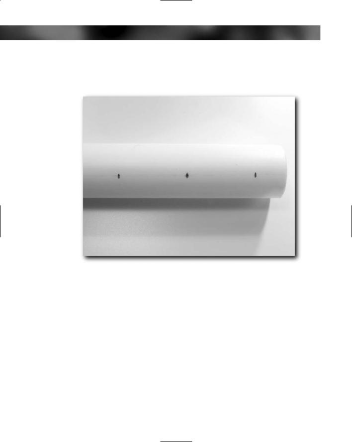
82 Part I — Hardware Hacks
and mark eight points that are each exactly 4.75 centimeters (1 7⁄8 inches) apart (see Figure 4-17). These have to be as accurate as you can manage because this is key to the antenna picking up the right frequency.
FIGURE 4-17: Building the helix coil
4.Drill the helix coil base: To do this you can either use a 1⁄16-inch bit to drill a hole at the last mark nearest each end of the helix coil base or you can use an awl to work through the plastic pipe.
5.Now you are ready to connect the helix wire to the antenna connection. If you are using a coaxial connector, all you now need to do is solder the end of the wire to the center of the connector. This will give you a robust and secure connection. If you aren’t using a connector, then just solder the helix coil wire to the center wire of the cable you are using. Pass the free end of the wire from the inside of the tube through the hole located 7⁄8 inch from the base end of the helix coil base.
Chapter 4 — Antenna Hacks 83
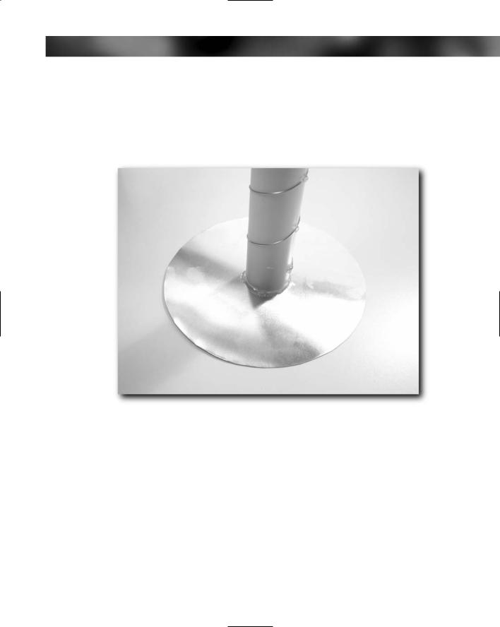
6.Now you need to attach the helix coil base to the ground plane. The easiest way I’ve found to do this is to use epoxy resin to attach the pipe to the ground plane. This ensures that the pipe is perpendicular to the ground plane. The epoxy resin also provides a robust and weatherproof joint. Another good way to create an effective joint is to use hot glue, although this doesn’t give you as much of a chance to get the coil perpendicular to the ground plane (see Figure 4-18).
FIGURE 4-18: Epoxy resin is great for attaching the helix coil base to the ground plane.
7.Make sure that you pull the helix wire tightly through the hole in the helix coil base before you begin to wind the helix wire around the base or the coil will quickly loosen. Start to wind the wire, working slowly and carefully. Wind it counterclockwise around the helix coil base, making sure that it is smooth and even on the tube. Use a dot of hot glue periodically to keep the wire in place (although don’t use too much hot glue). As each turn is completed, make sure the wire passes over each of the reference marks you made, and attach it in place with more hot glue. The partly completed helix coil is shown in Figure 4-19.
84 Part I — Hardware Hacks
FIGURE 4-19: Partly completed helix coil
8.Continue winding all the way to the top, taking care that the coils are equally spaced and smooth, and add hot glue to keep it in place as you go. When you get to the top, pass the wire through the hole and back inside the tube. Use pliers to pull the wire tightly through the hole, and bend it up toward the top of the pipe (see Figure 4-20). Secure this in place with more hot glue. Cut the wire off, leaving about 6 millimeters (1⁄4 inch) from where it makes the turn inside the pipe so it will stay in place.
9.Connect the antenna to the GPS and test it for proper operation.
10.Optionally, glue the cap to the top of the antenna and ensure that all your joints, connectors, and glued parts are sound.
A diagram of the finished antenna is shown in Figure 4-21.
You can now think about attaching the antenna. No matter what you do, however, don’t attach anything metallic to the ground plane (use glue or nylon nuts and bolts).
You can add glue some rubber-covered magnets to the base for automotive use. Make sure that these are strong magnets and test them to see how secure they are.