

- •Foreword
- •Preface
- •Contents
- •1.1 Introduction
- •1.2 Prologue
- •1.9 Expansion of the Greater Omentum
- •3: Distal Gastrectomy
- •4: Total Gastrectomy
- •5.2 Part II: Thoracic Manipulation
- •6: Right Hemicolectomy
- •7: Appendectomy
- •8.6 Internal Pudendal Artery and Its Branches
- •8.13 Lateral Ligament
- •8.16 Fascia Propria of the Rectum: Part II
- •9: Sigmoidectomy
- •13: Hemorrhoidectomy
- •14: Right Hemihepatectomy
- •15: Left Lateral Sectionectomy
- •16: Laparoscopic Cholecystectomy
- •17: Open Cholecystectomy
- •Bibliography
Open Cholecystectomy |
17 |
|
Abstract
Once you know what is ahead, you will be able to handle surgical instruments such as electrocautery devices and forceps with unwasted motions and cope with most standard surgeries. But you may still find surgery difficult for conditions such as severe cholelithiasis- associated cholecystitis (calculous cholecystitis). It is not easy to dig out the soft cystic duct and cystic artery from a rock-hard, thickened triangle of Calot, even when you know that
they are in there. This surgical procedure of open cholecystectomy is one to be reckoned with and requires a certain degree of skill and experience. This chapter describes how to perform this sometimes tricky procedure. Standard operation time is about 60 min but will depend on the severity of inflammation.
Keywords
Open cholecystectomy · Triangle of Calot Calculous cholecystitis
© Springer Nature Singapore Pte Ltd. 2020 |
419 |
H. Shinohara, Illustrated Abdominal Surgery, https://doi.org/10.1007/978-981-15-1796-9_17 |
|
420 |
17 Open Cholecystectomy |
|
|
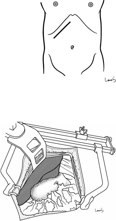
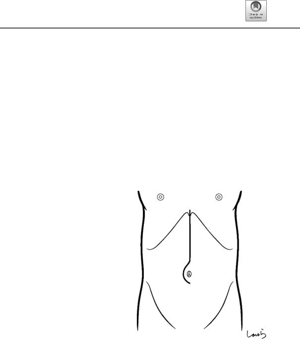
Fig. 17.1 Patients who require open cholecystectomy tend to have severe chronic cholecystitis, which complicates the dissection procedure. To obtain as good an operative field as possible, a right subcostal skin incision is advisable. The surgeon stands on the left side of the patient
Fig. 17.2 A wound retractor and a rib retractor are applied to secure the operative field
17 Open Cholecystectomy |
421 |
|
|
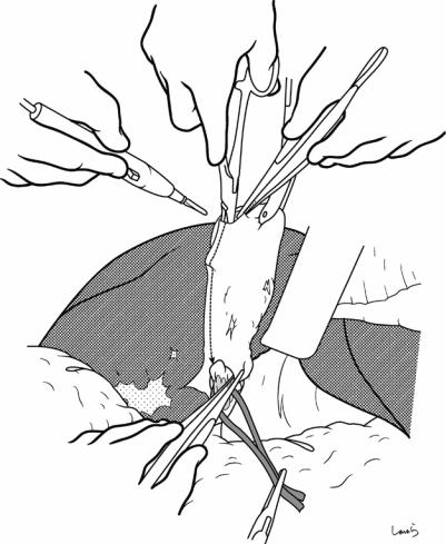
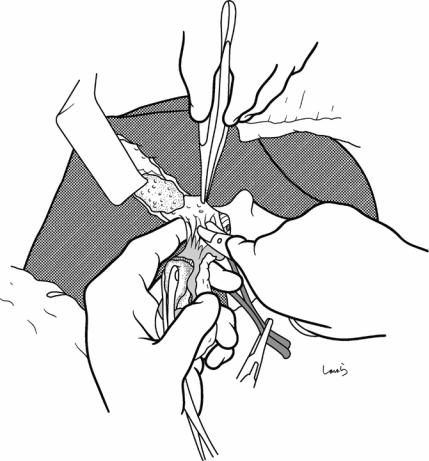
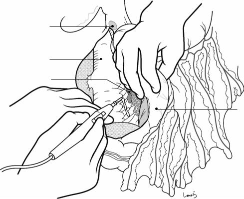
Fig. 17.3 Preparation for cholecystectomy: The severely inflamed gallbladder tends to be firmly adherent to not only the greater omentum but also the duodenum and transverse colon. These adhesions are released with Cooper scissors (a) and/or electrocautery (b). Because cholecystitis is a benign condition, the dissection should be performed as close as possible to the gallbladder to avoid inadvertently cutting into the intestine adherent to the gallbladder. It is also advisable to detach the greater omentum from the liver to secure an operative field on the right side of the gallbladder (b). This should also be performed slightly away from the liver because dissection too close to the liver can cause detachment of the liver capsule and a considerable amount of bleeding from the parenchyma
a
Transverse colon
b |
Duodenal bulbus |
Greater omentum adherent  to liver
422 |
17 Open Cholecystectomy |
|
|
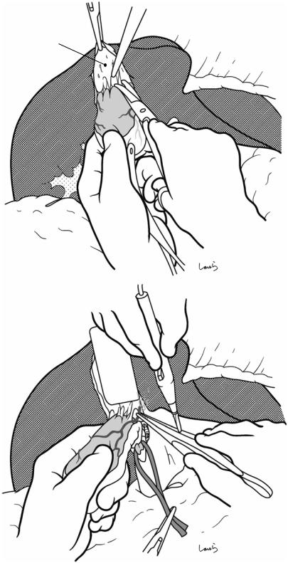
Pouch of
Hartmann
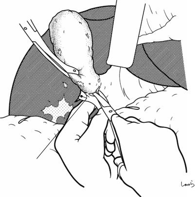
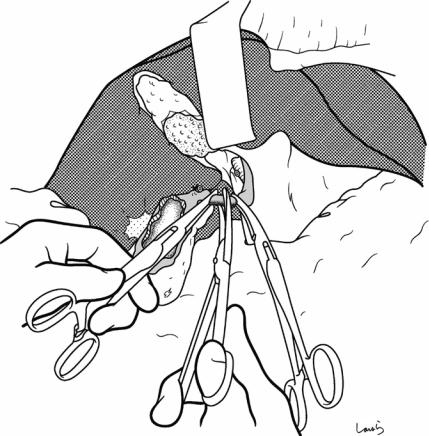
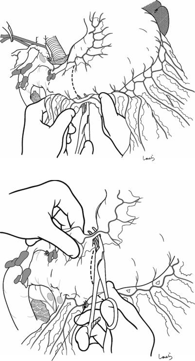
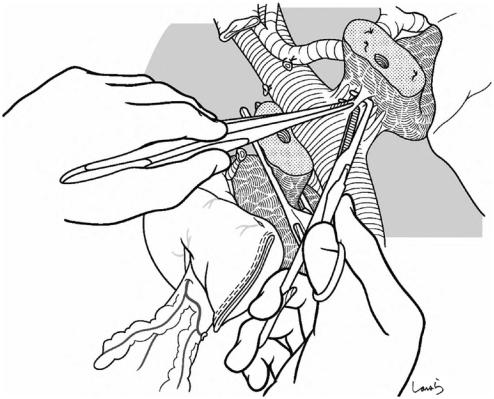
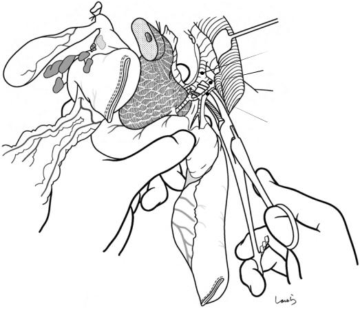
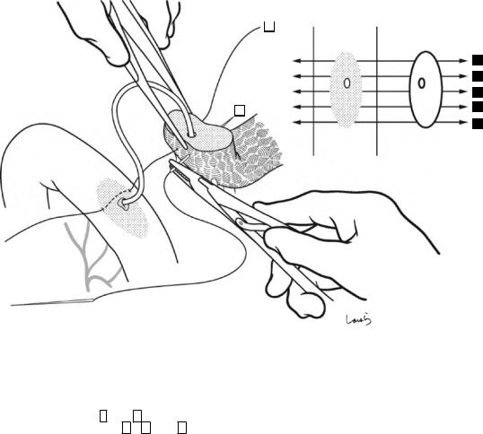
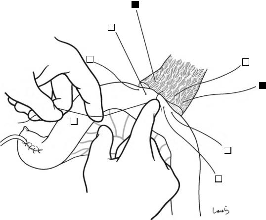
Fig. 17.4 When ready, the duodenum and the right colic flexure are pushed downward with the left hand to expose the entire underside of the liver. A surgical laparotomy sponge is placed over the left hand and spread over the intestine with long forceps. It is advisable to place the sponge firmly into the right colic flexure ( ) and the foramen of Winslow ( ) for complete coverage of the intestine
Although it is ideal for the first assistant to grasp the gallbladder base and pull it up to expand the triangle of
Calot, this is often difficult to do with a severely inflamed gallbladder. Also, if the gallbladder neck is rock-hard, pulling up the base will not generate enough tension in the triangle of Calot to expand it. This means the pouch of Hartmann should be grasped and pulled with forceps or, if this does not work, the surgeon can expand the triangle with their left hand
17 Open Cholecystectomy |
423 |
|
|
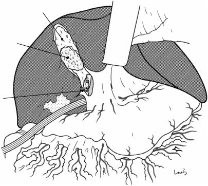
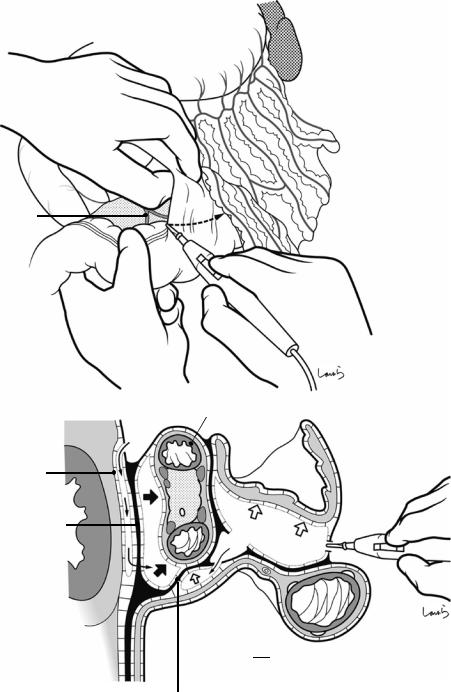
Sulcus of Rouviere
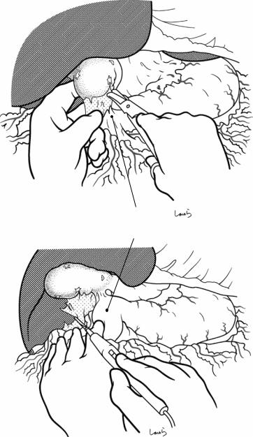
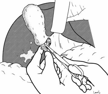
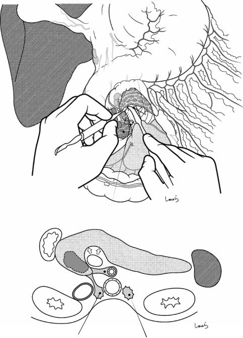
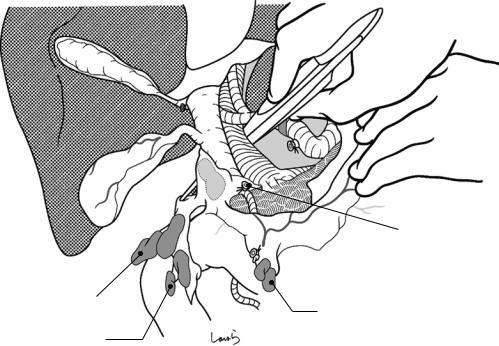
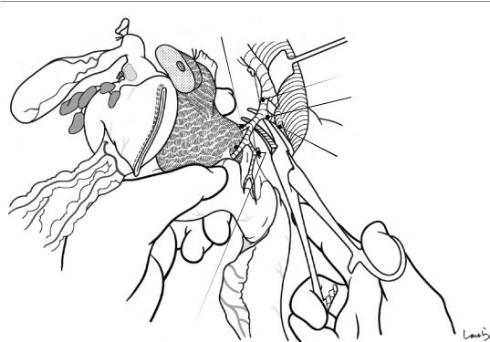
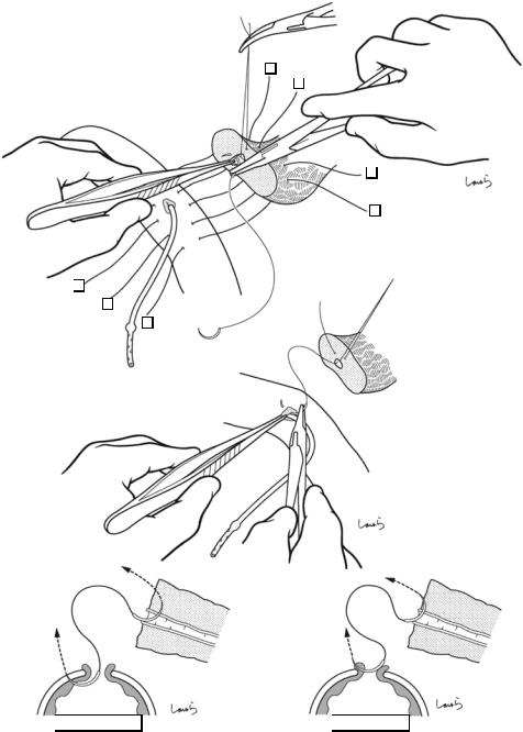
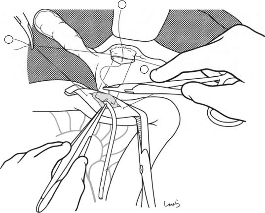
Fig. 17.5 The cystic duct is then explored, bearing in mind the course of the duct at the neck of the gallbladder based on preoperative imaging findings. An incision is made on the serosa over the putative anterior aspect of the cystic duct. If a space to accommodate dissection forceps can be created under the serosa, the serosa should be scooped and divided with electrocautery to minimize
bleeding. If the serosa is so hard that a space cannot be created, then the serosa should be incised superficially directly with Metzenbaum scissors. A serosal incision is also made on the posterior side of the cystic duct. During this step, be sure that the incision line is on the gallbladder side of the sulcus of Rouviere
424 |
17 Open Cholecystectomy |
|
|
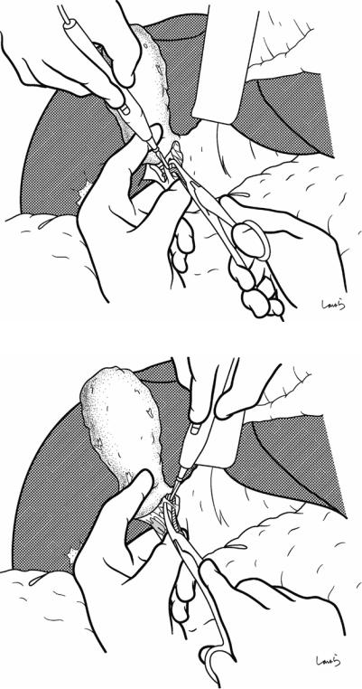
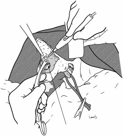
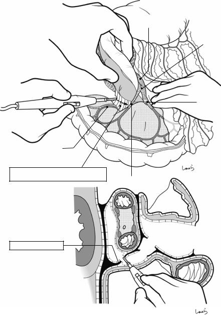
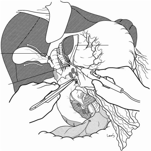
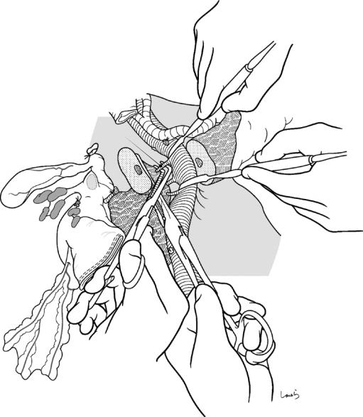
Fig. 17.6 Fibrous connective tissue surrounding the cystic duct is scooped with dissection forceps and divided with electrocautery. As was the case with laparoscopic cholecystectomy, it is advisable to proceed with the dissection from the lateral side of the cystic duct. When this step is complete, the cystic duct wall should be partially exposed
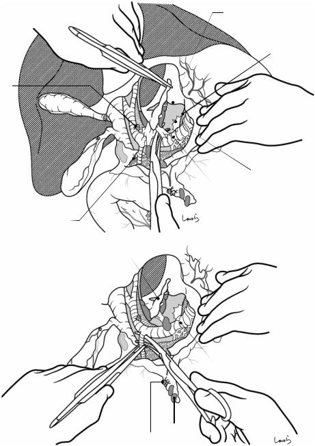
Fig. 17.7 We move next to dissection of the anterior and medial sides of the cystic duct, which is inside the triangle of Calot. If there is no inflammation, we should be able to identify a recess easily. This is unlikely though in cases where the triangle is rock-hard. We will need some patience to repeatedly identify fibrous, hard connective tissue that can be cut and then divided with electrocautery. If using dissection forceps does not work, Metzenbaum scissors can be used to cut the tissue little by little and proceed with the dissection
17 Open Cholecystectomy |
425 |
|
|
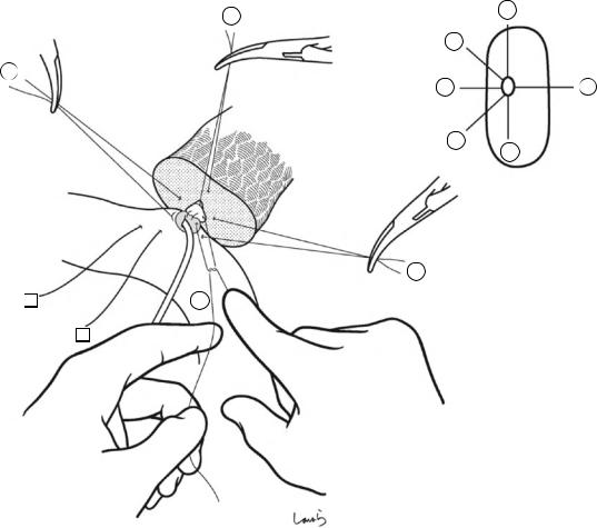
Fig. 17.8 As we proceed, we might encounter a robust cord-like structure that is slightly thicker than the previously dissected connective tissue. This is likely to be the cystic artery. When we have confirmed that the cord-like structure enters the gallbladder, we should ligate and divide it. Note, however, that even with enhanced vascularization of the gallbladder due to chronic inflammation, it is still possible that this structure is the right hepatic artery, especially when it is very thick. Due to inflammation of the neck of the gallbladder, the right hepatic artery tends to be located closer to the gallbladder than we might expect
426 |
17 Open Cholecystectomy |
|
|
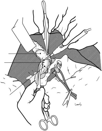
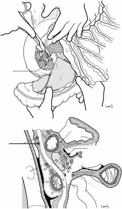
 Cystic a. (cut)
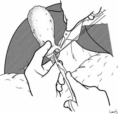
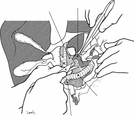
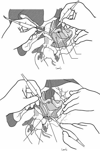
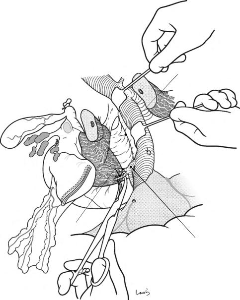
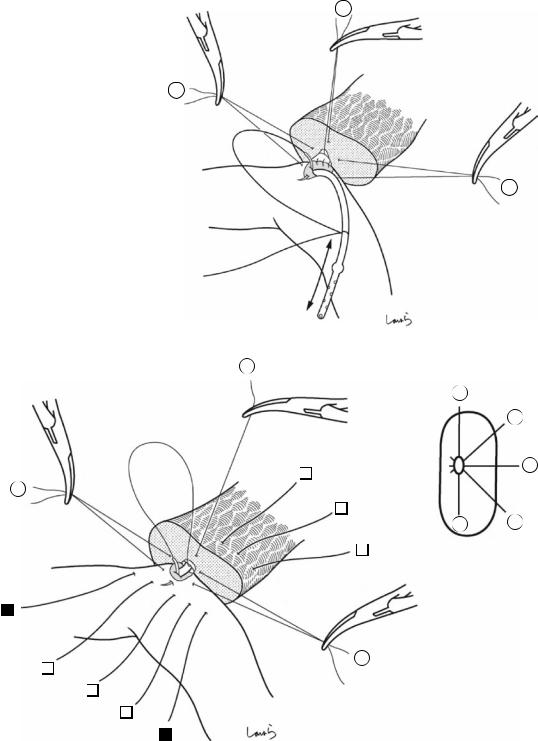
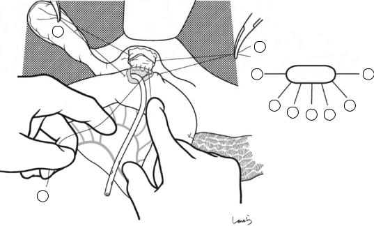
Fig. 17.9 As the dissection of the connective tissue around the cystic duct proceeds, a recess in the triangle of Calot gradually becomes apparent. Dissection forceps are passed through the recess, with the tip of the forceps guided by the left index finger to find the thinnest part. This way the forceps can be passed smoothly. If you are confident that the cord-like structure contains the cystic
duct, you can ligate it on the resection side. But if you are not completely confident, do not go beyond applying a vascular tape to it. Also, if the tissue is still too thick to be penetrated because of incomplete posterior dissection or because the elastic tissue adheres to the tip of the forceps, do not push the forceps and instead interrupt the connective tissue dissection around the gallbladder neck
17 Open Cholecystectomy |
427 |
|
|
Vascular tape applied to cystic duct
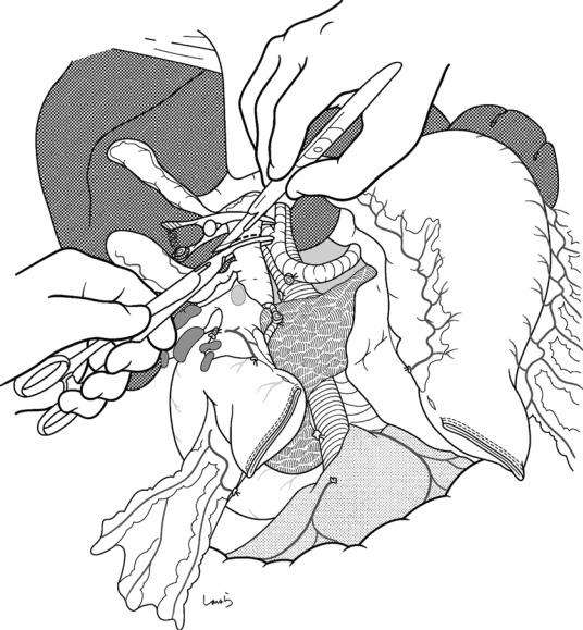
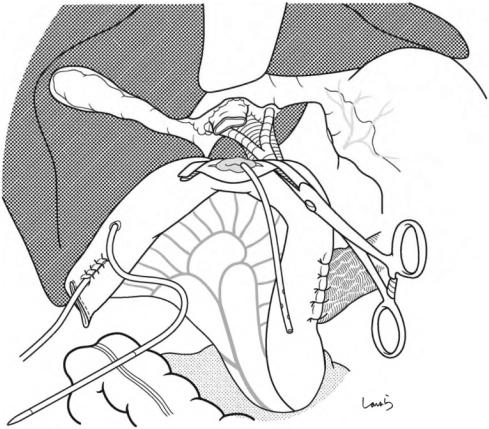
Fig. 17.10 Detaching the gallbladder from the liver bed: If inflammation has not spread to the body or base of the gallbladder, a circumferential serosal incision should be made before detaching the gallbladder from the liver bed. A small incision is made on the part of the serosa of the gallbladder base about 5 mm away from the liver with Metzenbaum scissors. The surgeon then slides dissection forceps under the serosa, and the first assis-
tant divides the serosa with electrocautery. The incision is connected to the preceding serosal incision at the neck. During the latter half of the incision, the first assistant pulls down the pouch of Hartmann, as shown, to straighten the incision line so that the surgeon can easily insert forceps. Once the serosal incision is completed on one side, the serosa on the contralateral side is incised in the same way
428 |
17 Open Cholecystectomy |
|
|
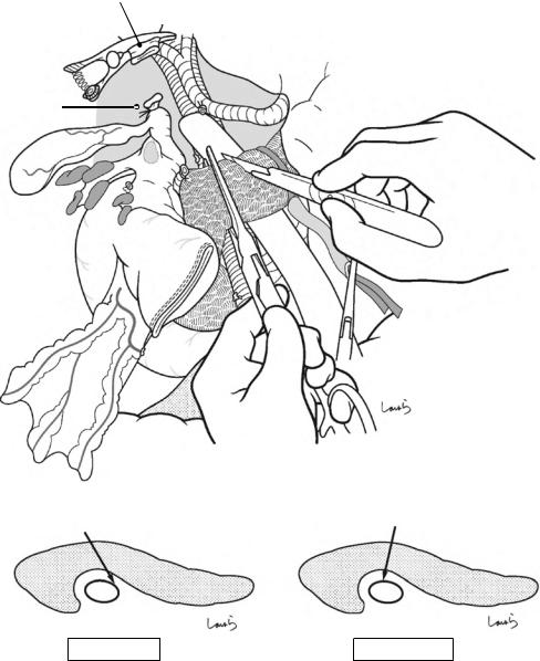
Fig. 17.11 While holding the gallbladder and gallbladder forceps with the left hand, the surgeon detaches the gallbladder from the liver bed with Cooper scissors held in the right hand (a). The dissection advances by entering an appropriate layer so that the muscle layer of the gallbladder is exposed and the connective tissue remains on the liver bed. When encountering a blood vessel that is obviously communicating with the liver bed during the dissection, the surgeon grasps the vessel with forceps and, after having the first assistant cauterize it with electrocautery, divides it with Cooper scissors (b). During the first half of the incision, the first assistant clears the view of the dissected part with the suction tube held in their right hand while grasping the serosal stump on the liver bed with Pean forceps held in their left hand, and during the latter half of the dissection pulls up the liver bed with a flat retractor to apply tension to the dissected part
a
Liver bed
b
17 Open Cholecystectomy |
429 |
|
|
Fig. 17.12 When the entire gallbladder is inflamed and the thickened wall is firmly adherent to the liver bed, it might not be feasible to perform the textbook procedure of detaching the gallbladder from the liver bed (Figs. 17.10 and 17.11). The only feasible option is then to proceed with dissection by directly cauterizing the adhesions with electrocautery while occasionally using the electrocautery tip as a spatula to identify the proper dissection layer. During this procedure, we need to be especially careful not to cut into the liver parenchyma (except when chole-
cystectomy including the liver bed is intended for suspected gallbladder cancer). A thick branch of the middle hepatic vein is located directly under the liver bed and damage to this vein by inadvertently cutting into the liver bed will cause unexpected massive bleeding. Hemostasis may well be difficult because of the small skin incision and the liver not being mobilized in many cases of cholecystectomy. If cholecystectomy including the liver bed is a preplanned procedure, then be sure to prepare an adequate operative field before starting the procedure
430 |
17 Open Cholecystectomy |
|
|
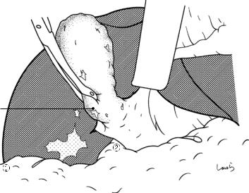
Fig. 17.13 When prioritizing preservation of the liver bed, we must recognize the risk of cutting into the gallbladder wall and perforating it. If perforation occurs, aspirate the bile, remove the stones, and redirect the dissection to the proper layer. This, at the same time, helps determine the thickness of the gallbladder wall, which makes the subsequent dissection procedure quicker
Hole in gallbladder wall
17 Open Cholecystectomy |
431 |
|
|
Gallbladder wall remaining on liver bed
Gallbladder neck
Inner side of gallbladder wall
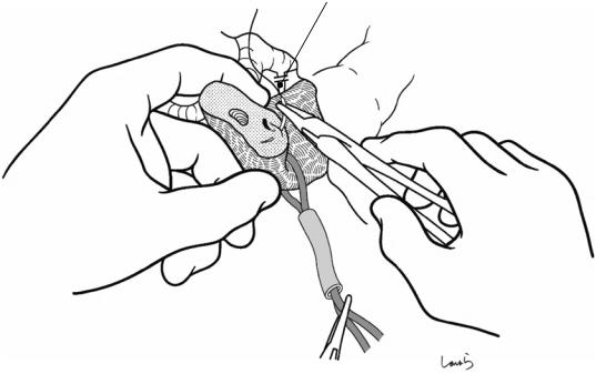
Fig. 17.14 Sometimes the gallbladder wall is so firmly adherent to the liver bed that the two cannot be separated despite trying to redirect the dissection, and this would mean that the liver parenchyma has to be detached together with the gallbladder wall. In such cases, as a compromise, we can leave the adherent portion of the wall on the liver bed and excise only the nonadherent portion. However, when the dissection approaches the neck of the gallbladder, the wall has to be crossed and detached from
the liver bed. This results in a resected specimen of the gallbladder that has a large gaping hole. In such cases, I recommend that you take this opportunity to examine the inner side of the gallbladder neck because it might help identify the entrance to the cystic duct and allow you to confidently identify this duct. The surface of the gallbladder mucosa remaining on the liver bed should then be thoroughly cauterized with electrocautery
432 |
17 Open Cholecystectomy |
|
|
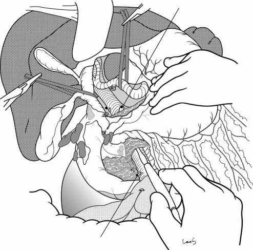
Fig. 17.15 Finally, while feeling the thickness of the remaining connective tissue (the intervening “mesocyst” between the gallbladder and the extrahepatic Glissonean pedicle) with the ball of the left index finger, the connective tissue is scraped off the gallbladder neck with Cooper scissors. It is advisable to proceed with dissection while holding the scissors nearly perpendicular to the tissue to
be dissected, which ensures that the dissection layer stays near the gallbladder until the end. Now the end of the operation is in sight, you may feel like cutting through the tissue quickly, but if you have not encountered the cystic artery, consider that it might be contained within this connective tissue and be ready to ligate and divide any suspected cord-like structure you encounter
17 Open Cholecystectomy |
433 |
|
|
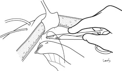
Fig. 17.16 After dissecting the remaining connective tissue around the cystic duct, the cystic duct is excised by doubleligating with a 3-0 Vicryl suture and dividing it at its proximal end
434 |
17 Open Cholecystectomy |
|
|
Liver bed
Remaining gallbladder wall (cauterized with electrocautery)
Cystic duct
Fig. 17.17 The abdominal cavity, especially the liver bed, is then examined to confirm hemostasis. Any incomplete hemostasis should be treated by cauterization with electrocautery (spray coagulation). Mikulicz gauze is removed and the small intestine is repositioned so that it does not migrate over the colon into the space under the
liver. If bile leakage occurred during the operation, be sure to wash the abdominal cavity thoroughly. An 8-mm duple drain is inserted via the right abdominal wall into the foramen of Winslow and the operation is completed by closing the abdominal wall, suturing in three layers
Pancreaticoduodenectomy: 18
Whipple Procedure
Abstract |
|
|
Keywords |
|
This chapter describes subtotal stomach- |
Pancreaticoduodenectomy · Whipple |
|||
preserving pancreaticoduodenectomy, a major |
procedure · Pancreaticojejunostomy |
|||
challenge for gastrointestinal surgeons. Akin |
|
|
||
to the individual medley in a swimming com- |
|
|
||
petition, this operation involves advanced |
|
|
||
resection and reconstruction techniques. This |
|
|
||
chapter describes in detail a modified Whipple |
|
|
||
procedure as a reconstruction technique and a |
|
|
||
pancreatic duct to full-thickness jejunum |
|
|
||
anastomosis as a pancreaticojejunostomy |
|
|
||
technique. In the later stage of the operation, |
|
|
||
gastrojejunostomy and Braun enteroenteros- |
|
|
||
tomy are performed using instruments. The |
|
|
||
standard operation time is 6 h. |
|
|
||
Fig. 18.1 The surgeon stands on the right side of the patient and makes an upper abdominal midline incision extending from the xiphoid process to the right of the umbilicus. The peritoneum is incised to the right of the round ligament of the liver to open the abdomen. After placing a wound retractor, exploration of the abdominal cavity is performed and the liver, pouch of Douglas, and other structures are examined
© Springer Nature Singapore Pte Ltd. 2020 |
435 |
H. Shinohara, Illustrated Abdominal Surgery, https://doi.org/10.1007/978-981-15-1796-9_18 |
|
436 |
18 Pancreaticoduodenectomy: Whipple Procedure |
|
|
No.12b LN
Inf. vena cava
No.13 LN
Descending part of duodenum
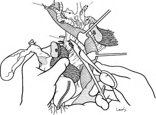
Fig. 18.2 The liver is retracted cranially with an Octopus retractor to secure a view of the operative field, followed by mobilization of the duodenum (Kocher maneuver). The dissection should be done adequately beyond the anterior surface of the inferior vena cava up to the abdominal aorta. For a smooth procedure, the speed at which the surgeon advances the electrocautery device and the force with which the first assistant pulls the duodenum must be well synchronized. As shown in the sagittal cross section in Fig. 18.3b, the correct route for layer separation is to
enter the space between the fusion fascia of Treitz (a fused fascia formed by collision of the duodenal part of the pancreatic head with the retroperitoneum) and the visceral fascia, with the former fascia remaining on the abdominal wall side (thick black arrow 1 in Fig. 18.3b). If tumor invasion to the connective tissue on the posterior side of the pancreas is suspected, the dissection should be done in an appropriate layer so that the fusion fascia remains attached to the resection side (route indicated by a thin arrow 1′ in Fig. 18.3b)
18 Pancreaticoduodenectomy: Whipple Procedure |
437 |
|
|
a
Acc.
R colic v.
b |
Duodenal bulbus |
1’ |
Greater omentum |
Fascia of |
|
Gerota |
1 |
|
Panc |
|
. |
Fusion fascia |
2 |
of Treitz |
2 |
|
1
3
Fusion fascia between greater omentum and transverse mesocolon
Fusion fascia between horizontal part of duodenum and transverse mesocolon
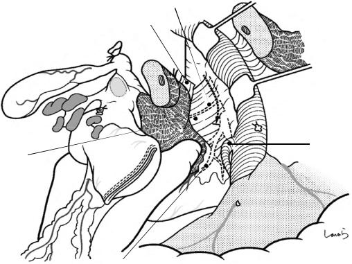
Fig. 18.3 The greater omentum is now detached from the transverse mesocolon (white arrow 2 in b), and divided at its attachment to the omental tenia. This procedure advances in the opposite direction to the procedure in total gastrectomy (Fig. 4.11) but in the same dissection layer (see also Fig. 4.13a). When the right border of the omental
bursa is reached from the back (right) side, it is incised and the incision is extended toward the anterior surface of the pancreatic body. The transverse mesocolon is also detached from the uncinate process of the pancreas and the anterior aspect of the horizontal part of the duodenum (white arrow 3 in b)
438 |
18 Pancreaticoduodenectomy: Whipple Procedure |
|
|
a
R colic a. & v.
Web-like fused fascia remaining between duodenum and transverse mesocolon
b
Web-like fused fascia
Fig. 18.4 If we have carried out the dissection in the correct layer, we can now see a web-like fused fascia remaining between the duodenum and the transverse mesocolon (a). This fascia is divided with electrocautery (b). This corresponds to what we see in right hemicolectomy where a remnant of the fusion fascia of Toldt can be seen after the ascending colon has been mobilized from two directions (see Fig. 6.13a and b). On the way, the accessory right colic vein is encountered as a stretched cord-like structure and should be ligated and divided. Once the dissection has reached the superior mesenteric vein (SMV), the duodenal part of the pancreatic head is fully mobilized. Then, while pulling the horizontal part of the duodenum, the connective tissue around the duodenum is scraped off with Cooper
SMV
Gastrocolic trunk of Henle
Mid. colic v.
Acc. R colic v.
scissors toward the ligament of Treitz to lengthen the duodenal neck. Even if we detach the duodenum so strongly as to open the ligament of Treitz from this side, we still have a long way to go and can see that the ligament of Treitz is a long structure. This procedure mainly dissects the dorsal side of the horizontal part of the duodenum and eventually reaches the back side of the ligament of Treitz, forming a hole on the retroperitoneum of a recessed part (the paraduodenal recess; see Fig. 18.25) between the proximal jejunum and the inferior mesenteric vein (IMV). Also, at this point, the right colic vessels are already exposed on the dissected surface of the transverse mesocolon because these vessels are located cranial to the horizontal part of the duodenum, as described in Chap. 6 on right hemicolectomy
18 Pancreaticoduodenectomy: Whipple Procedure |
439 |
|
|
Direct br.
L gastric v.
PSPDV
PV
R gastroepiploic v.
Splenic v.
Infrapyloricv.
 IMV
IMV
ASPDV
Gastrocolic trunk of Henle
 Mid. colic v.
Acc. R colic v.
 PIPDV
PIPDV
AIPDV |
SMV |
|
J1v |
Fig. 18.5 Anatomy of the venous system around the pancreatic head: There are innumerable possible variations, so the most characteristic pattern is shown here. The anterior superior pancreaticoduodenal vein (ASPDV; ), which we talked about a lot in Chaps. 3 and 4 on gastrectomy, converges with the right gastroepiploic vein and the accessory right colic vein to form the gastrocolic trunk of Henle and drains into the SMV. The anterior inferior pancreaticoduodenal vein (AIPDV; ) drains into the SMV at a level slightly lower than the gastrocolic trunk of Henle,
usually after forming a common trunk with the posterior inferior pancreaticoduodenal vein (PIPDV; ) and the first jejunal vein (J1v). Another vein, the posterior superior pancreaticoduodenal vein (PSPDV; ), drains into the portal vein at the level of the upper border of the pancreas. Several more short veins also drain from the pancreatic head directly into the portal vein or the SMV. These veins must be identified and dissected accurately to prevent bleeding during pancreaticoduodenectomy
440 |
18 Pancreaticoduodenectomy: Whipple Procedure |
|
|
a
R gastroepiploic v. |
6 |
|
ASPDV
 SMV
SMV
Acc. R colic v. (ligated)
b
|
|
|
|
|
|
R gastropiploic v. |
No.12b LN |
|
|
|
|
||
6 |
|
|
|
Fusion fascia between greater |
||
|
|
|
17 omentum and transverse |
|||
6 |
6 |
|
17 |
mesocolon (cut, *) |
||
|
R gastroepiploic v. + ASPDV |
|||||
ASPDV |
|
|
|
17 |
|
|
|
|
|
||||
1717 |
* |
|
||||
|
|
|
|
|
|
|
No.13 LN 
Gastrocolic trunk
of Henle (ligated)
Acc. R colic v.
Fig. 18.6 The gastrocolic trunk of Henle is ligated and divided (a). The superior mesenteric lymph nodes, which are referred to as the No. 14v nodes during gastric cancer surgery, are included in the No. 17b inferior prepancreatic head lymph nodes of Group 1 according to the Japanese classification of pancreatic carcinoma. The sagittal cross
section at the level of the portal vein and the SMV (b) shows the gradual revealing of the contour of the duodenal part of the pancreatic head (which is to be resected) by procedures such as Kocher maneuver, detachment of the greater omentum from the transverse mesocolon, and division of the gastrocolic trunk of Henle
18 Pancreaticoduodenectomy: Whipple Procedure |
441 |
|
|
a
SMV
6
Tumor
|
Gastrocolic trunk of Henle (ligated) |
b |
|
Descending |
PLph-I |
part of |
|
duodenum |
|
Spleen
Cancer
SMV
SMA
PLph-II 
Ao
IVC
R celiac ganglion |
L celiac ganglion |
|
Fig. 18.7 Now, to determine whether the carcinoma is resectable, the gap between the pancreas and the SMV is entered with two dissectors (a). This is just like opening the front door to someone’s house to see if they will let you in. If both structures can be completely separated to allow the dissectors to reach the upper border of the pan-
creas, then the tumor is resectable and subsequent procedures can commence. In actual cases, portal invasion of cancer of the head of the pancreas commonly occurs on the right posterior side (b) and cannot always be identified in the current procedure, although we can still determine whether portal reconstruction is possible
442 |
18 Pancreaticoduodenectomy: Whipple Procedure |
|
|
Cystic a.
b 12
R gastric a. & v.
No.12p LN
Lesser omentum
5
12a
6
17
17
Fig. 18.8 Lymph node dissection is performed between the hepatoduodenal ligament and the upper border of the pancreas. An incision is made on the lesser omentum and extended transversely on the peritoneum of the anterior surface of the hepatoduodenal ligament toward the triangle of Calot. After the cystic artery is ligated and divided in the triangle, the gallbladder is detached from the liver bed (white arrows). The cystic duct should not be divided
and should be excised with the specimen. Then, the proper hepatic artery is identified and the connective tissue around the artery, which contains the No. 12a lymph nodes and nerve fibers, is removed with electrocautery by gathering them toward the duodenum. On the way, the right gastric artery and vein are ligated and divided at their root once exposed
18 Pancreaticoduodenectomy: Whipple Procedure |
443 |
|
|
a
R gastric a. (root)
Gastroduodenal a. 
|
PSPDA |
b |
No.8a/ p LN (dissected) |
|
Proper hepatic a.
Post. wall of omental bursa
L gastric v.
R celiac ganglion Common hepatic a.
12b
Common hepatic a.
No.5,12a LN
R gastric a. (ligated)
Fig. 18.9 With the stomach pulled caudally to obtain a clear view of the upper border of the pancreas, an incision is made on the retroperitoneum of the posterior wall of the omental bursa (a). The connective tissue around the common hepatic artery, which contains the No. 8a and 8p lymph nodes and nerve fibers, is dissected with electrocautery, orientated from the root of the left gastric artery toward the gastroduodenal artery, which is the opposite direction to that for gastric cancer surgery. Because there may be tumor invasion to the nerve, we should dissect over the arterial surface while staying in a layer that allows us to remove a net-like nerve bundle surrounding
the arterial surface (slightly deeper than the dissection layer for gastric cancer operation). Because these lymph nodes are connected to the No. 12p nodes, they should not be separated and will be dissected en bloc later (see Figs. 18.10 and 18.11). After completing the dissection around the proper hepatic artery and the common hepatic artery and exposing the root of the gastroduodenal artery, the artery is ligated and divided (b). If anastomotic leak of the pancreaticojejunostomy occurs, rupture or aneurysm formation at the stump of the gastroduodenal artery can be fatal, so the ligation should be made carefully to avoid damaging the intima of the artery
444 |
18 Pancreaticoduodenectomy: Whipple Procedure |
|
|
Ant. surface of |
No.12p LN |
portal v. |
|
Proper hepatic a.
Common hepatic a.
Gastroduodenal a. (root)
Fig. 18.10 Periportal lymphadenectomy is performed next. The surgeon retracts the proper hepatic artery with the left thumb to expose the anterior surface of the portal vein, inserts the remaining four fingers into the foramen of Winslow to push the No. 12p lymph nodes located behind the hepatoduodenal ligament out to the left of the portal vein, and asks the first assistant to grasp the nodes with for-
ceps. Maintaining this position, the surgeon detaches the lymph nodes from the portal vein wall with Metzenbaum scissors. The dissection should proceed in an appropriate layer so that the portal vein wall is exposed with no residual membrane over the surface of the portal vein. This helps to accurately identify and cauterize all small branches draining from the lymph nodes into the portal vein
18 Pancreaticoduodenectomy: Whipple Procedure |
445 |
|
|
b
12
Gastroduodenal a. (root)
No.12p LN |
No.5,12a LN |
|
|
No.8a/p LN |
|
Fig. 18.11 After isolating the No. 12p portal lymph nodes isolated, they are coupled with the previously detached No. 8a and 8p nodes, brought behind the com-
mon bile duct, and attached to the No. 12b bile duct lymph nodes. Before doing this, the proper hepatic artery should be taped and retracted to the left
446 |
18 Pancreaticoduodenectomy: Whipple Procedure |
|
|
a
Common hepatic a.
Gastroduodenal a. (root)
Portal v.
b
Gastroduodenal a. |
PSPDV |
|
(ligated) |
||
R gastric a. (ligated) |
||
|
Fig. 18.12 We now move on to lymphadenectomy along the right border of the portal vein. Using two dissectors, the right wall of the portal vein is pushed with the dissector held by the right hand, while the surrounding connective tissue is detached with the dissector held by the left hand (a). As the dissection proceeds downward, the posterior superior pancreaticoduodenal vein (PSPDV) can be identified as it drains from the upper border of the pancreas into the right wall of the portal vein. This vein is ligated and divided (b). To identify these small veins easily, we should advance the dissection in an appropriate
layer so that the portal vein wall is exposed with no residual membrane over it
The dissection of the hepatoduodenal ligament should be performed based on the concept that except for the connective tissue around the hepatic artery and the portal vein, which are to be preserved, all other connective tissues should remain attached to the bile duct or the duodenum, which are to be excised
18 Pancreaticoduodenectomy: Whipple Procedure |
447 |
|
|
PSPDV (ligated)
Tip of dissector passed through layer
|
|
b |
||
|
|
|
|
|
|
|
12 |
|
|
p |
|
12a |
||
|
|
|
||
12 |
8a |
6 |
||
8p |
||||
|
|
|
||
Gastrocolic trunk of Henle (ligated)
Fig. 18.13 A dissector is again inserted into the layer that was previously entered to detach the SMV from the pancreatic parenchyma (Fig. 18.7), and it is advanced until its tip is beyond the upper border of the pancreas
Up to this point, pancreaticoduodenectomy can be completed. After this point, the operation enters the stage of no-return
448 |
18 Pancreaticoduodenectomy: Whipple Procedure |
|
|
Fig. 18.14 Transection of the stomach: The greater omentum is incised toward an imaginary transection line of the stomach set in the antrum 3–4 cm proximally from the pyloric ring. An arcade formed by the right gastroepiploic artery and vein is ligated and divided when reached
Fig. 18.15 The corresponding arcade on the lesser curvature side is also ligated and divided
R gastroepiploic a. (ligated)
18 Pancreaticoduodenectomy: Whipple Procedure |
449 |
|
|
Fig. 18.16 The stomach is transected with a linear stapler. Because the stomach wall is relatively thick around the antrum, a green cartridge (3.5 mm) should be used. The
5–6 cm range from the transection line toward the greater curvature should be cleared of any gastric wall branches because this area will be anastomosed to the jejunum during reconstruction
|
6 cm |
- |
|
5 |
|
450 |
18 Pancreaticoduodenectomy: Whipple Procedure |
|
|
Stump of stomach
Fig. 18.17 Transection of the bile duct: The common hepatic duct is clamped with a bulldog clamp and divided. The stump on the resection side is ligated with a 1-0 silk suture. The bulldog clamp may be kept in place until reconstruction if percutaneous transhepatic cholangiod-
rainage (PTCD) has been placed. Otherwise, the clamp should be removed occasionally, and accumulated bile should be suctioned to prevent an excessive increase in biliary pressure
18 Pancreaticoduodenectomy: Whipple Procedure |
451 |
|
|
|
|
a |
Common hepatic duct |
|
Hepatic duct (ligated)
spatula
Vascular tape
b |
c |
|
SMV |
SMV |
Bad transection |
Good transection |
Fig. 18.18 Transection of the pancreas: After an imaginary transection line is set on the pancreas along and above the SMV (the thinned area), a vascular tape is applied to the portion about 2 cm caudal to the line and lightly tightened with a short-cut Nelaton catheter. A stump clamp is applied on the resection side of the line. With a small spatula (brain spatula) placed between the pancreas and
the SMV as an underlay, the pancreas is transected with a pointed blade, ensuring that the dissection plane is perpendicular to the surface (a). Because the surgeon is on the right side of the patient, the dissection plane tends to be like that shown in (b). Instead, the plane in (c), which has a longer dorsal line of the pancreas, should be created for ease of later pancreaticojejunostomy
452 |
18 Pancreaticoduodenectomy: Whipple Procedure |
|
|
Dorsal panc. a.
Fig. 18.19 After transecting the pancreas, the cut surface is examined to identify the main pancreatic duct. If the duct is distended as shown, then no additional procedure is needed. If it is narrow, we need to insert a pancreatic duct tube and confirm that the tube can be advanced without resistance. The tube can be kept in place until reconstruction to drain pancreatic juice out of the wound, as long as it does not interfere with the subsequent procedures
Vigorous bleeding might occur from a small artery on the cut surface and hemostasis can be achieved by placing
a U-shaped 4-0 PDS suture at the bleeding point. In parallel with bleeding control, the vascular tape used to tighten the neck of the pancreatic stump is gradually loosened and removed. If the bleeding is difficult to control due to vigorous blood flow, one of the supplying arteries (the dorsal pancreatic artery) can be dissected
18 Pancreaticoduodenectomy: Whipple Procedure |
453 |
|
|
Fig. 18.20 For ease of later anastomosis, the connective tissue on the posterior side of the pancreas near the stump is dissected to obtain a “long neck”
454 |
18 Pancreaticoduodenectomy: Whipple Procedure |
|
|
Direct br. draining from pancreatic head into SMV
Second assistant’s left hand
Fig. 18.21 The right wall of the SMV is trimmed. Short veins draining directly from the pancreatic head into the SMV are identified, scooped with right-angle dissection forceps, and ligated and divided. There are three to four such veins. During this procedure, the second assistant pulls the pancreatic head to the right with the stump clamp held in the left hand, while the first assistant pulls the SMV to the left with two dissectors to secure the operative field. Once one branch is dissected, the dissector is repositioned deeper to dissect the next branch that drains into a deeper portion (into the posterior wall of the SMV). This procedure is repeated over the right three-quarters of the
circumference of the SMV to which the pancreas is attached. For accurate identification of the small branches, the dissection should also proceed in an appropriate layer so that the wall of the SMV is exposed with no residual membrane over it. After all of the small branches have been dissected, the pancreatic stump on the resection side is ligated with a 1-0 silk suture and the stump clamp is removed. Because this area is most commonly affected by portal invasion of pancreatic head cancer, we may need to consider combined resection of the portal vein when the dissection cannot be performed safely
18 Pancreaticoduodenectomy: Whipple Procedure |
455 |
|
|
SMA
I
SMV
II
 Gastrocolic trunk of
Henle (ligated)
PIPDV
AIPDV
J1v (common trunk with A/PIPDV)
Fig. 18.22 Dissection of the inferior pancreaticoduodenal vein: When the dissection along the right wall of the SMV reaches the uncinate process, the first assistant exchanges the dissectors for two curved retractors and pulls the SMV to the left over the superior mesenteric artery (SMA). As the dissection continues, the root of the first jejunal vein (J1v) is encountered near the upper border of the ascending part of the duodenum. This is because when the SMV is twisted, the J1v, which enters the SMV from its left posterior aspect in the natural position, passes behind the SMV as if winding around it and enters it from the right posterior aspect. Inserting forceps without knowing this may cause massive bleeding. Also, the anterior/ posterior inferior pancreaticoduodenal veins (A/PIPDV) often form a common trunk with the J1v, in which case
these veins drain into the J1v near its root. By ligating and dividing the IPDV at this portion, the communication between the pancreatic head and the portal system is completely shut down. Variations are common though, so the dissection should advance based on a full understanding of the course and branching pattern of the J1v
The remaining task is to dissect arteries. The arterial branches to be dissected are embedded in a nerve bundle referred to as the pancreatic head nerve plexus (PLph). As shown in Fig. 18.7b, the nerve bundle extending from the right celiac ganglion into the upper medial border of the uncinate process is identified as the PLph-I (I) and the broad bundle extending from the superior mesenteric plexus into the uncinate process along the entire length of its medial border is identified as the PLph-II (II)
456 |
18 Pancreaticoduodenectomy: Whipple Procedure |
|
|
Root of J1a
(common trunk with IPDA)
Root of J1v
Duodenojejunal junction
IPDV
PIPDA
AIPDA 
J1a / v
Anastomosing a.
Mid. colic v.
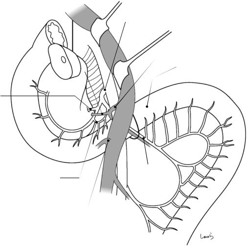
Fig. 18.23 Anatomy of the inferior pancreaticoduodenal artery (IPDA): The IPDA branches from the SMA near the upper border of the duodenum and often forms a common trunk with the first jejunal artery (J1a) in almost one in two cases. The root of the IPDA is usually undivided, as shown, but it may be split into the anterior and posterior branches. Also, regardless of whether or not the IPDA and the J1a form a common trunk, an anastomosing artery connecting the two arteries is seen in about 60% of cases
The J1a crosses the front of the duodenum and comes out of the ligament of Treitz along with the J1v. Because
the artery does not give off any branches until reaching the lower border of the proximal jejunum, the anterior and posterior walls of the duodenum can be easily detached from the ligament of Treitz
We should keep in mind the discontinuity of the direction of blood vessel attachment between the proximal jejunum (which has a distinct mesentery and is supplied by blood vessels entering from the lower medial direction) and the ascending part of the duodenum (which is supplied by a short vascular pedicle extending from the anastomosing artery)
18 |
Pancreaticoduodenectomy: Whipple Procedure |
457 |
|
|
|
a |
R celiac ganglion |
L gastric a. |
Common hepatic a. 
Celiac piexus
PLph-I
Fig. 18.24 The PLph is then dissected. The first assistant retracts the SMV to the left with two curved retractors. The surgeon pulls the pancreatic head laterally to the right with the left hand to apply tension to the nerve bundle of the PLph-I. The nerve bundle is the scooped with dissection forceps and divided in stages with electrocautery (a). Then, with the pulsating SMA held between the thumb and middle finger of the left hand, the PLph-II is dissected along the right border of the SMA (b). This nerve bundle should be ligated and divided because it may contain a branch directly draining from the SMA into the uncinate process. In this operative field,
the dissection should be stopped before reaching the root of the IPDA because the root can be exposed more clearly and trimmed more cleanly by drawing out the duodenum after jejunal transection and pulling the entire specimen to the right
Given that the cancer of the pancreatic head may have spread into the PLph, we should, at the very least, resect the plexus located to the right of the SMA. However, because complete circumferential resection of this plexus always results in refractory diarrhea, determine the range of dissection by considering the balance between risk and possibility of cure
458 |
18 Pancreaticoduodenectomy: Whipple Procedure |
|
|
|
Direct br. draining from SMA |
b |
into uncinate process |
|
|
|
PLph-I (dissected) |
 SMA
SMA
 Root of J1a
Root of J1v
PLph-II
IPDA
Fig. 18.24 (continued)
18 Pancreaticoduodenectomy: Whipple Procedure |
459 |
|
|
a
SMV |
Vasa recta |
First marginal a/v branching from J1a/v
J1a/v
b
SMV |
IMV |
Paraduodenal recess
J1a/v
Fig. 18.25 Transection of the jejunum: With the transverse colon everted cranially, the peritoneum is divided along the right border of the proximal jejunum. If circumstances permit with respect to lymph node dissection, the J1a/v should be preserved and, after ligating and dividing two to three straight vessels, an appropriate route should be determined to divide the first marginal artery/vein branching from the J1a/v (a)
The jejunum is then everted to the right and an incision is made on the peritoneum of a recess between the
left border of the proximal jejunum and the inferior mesenteric vein (IMV) (the paraduodenal recess) and connected to the incision made on the right side (b). The peritoneum on this side is the posterior side of the ligament of Treitz and should already be perforated if the Kocher maneuver was performed completely earlier (Fig. 18.4). After trimming the intestinal wall, the jejunum is transected with a linear stapler at the position indicated by the arrow
460 |
18 Pancreaticoduodenectomy: Whipple Procedure |
|
|
SMA
IPDA
SMV
Ligament of Treitz
Fig. 18.26 After it is confirmed that the anterior, posterior, and lower walls of the duodenojejunal junction are completely detached from the inner surface of the
ligament of Treitz, the resection-side stump of the jejunum is pulled and allowed to pass behind the SMA/V to the right of it
18 Pancreaticoduodenectomy: Whipple Procedure |
461 |
|
|
a
Common trunk
J1a
Anastomosing a.
Fig. 18.27 The resection specimen is now anchored only by the IPDA. The entire specimen is grasped by hand and pulled to the right to apply tension to the cord-like structure composed of the IPDA and the nerve bundle. The arterial wall is exposed by carefully removing the nerve
fibers surrounding the artery. The anastomosing artery between the IPDA and J1a is ligated and divided close to J1a (a), followed by ligation and division of the IPDA at the level of the common trunk with the J1a (b). This allows the specimen to be excised
462 18 Pancreaticoduodenectomy: Whipple Procedure
b
AIPDA |
PIPDA |
|
|
|
Common trunk |
|
J1a |
Root of J1a
Anastomosing a. (ligated)
Fig. 18.27 (continued)
18 Pancreaticoduodenectomy: Whipple Procedure |
463 |
|
|
a
Hole
Hole
IMV
Mid. colic v. |
SMV |
b
Planned site of hepaticojejunostomy
Hole formed on paraduodenal recess (not to be used)
Planned site of gastrojejunostomy
Planned site of Braun enteroenterostomy
Planned site of
pancreaticojejunostomy
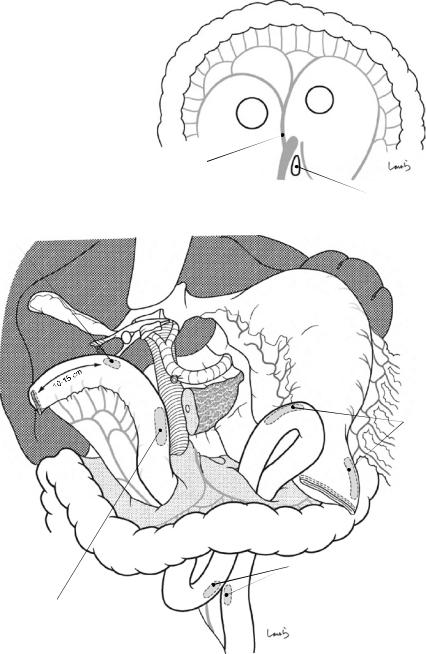
Fig. 18.28 For reconstruction, we use the Whipple procedure here as the standard reconstruction procedure. Two holes are made on the transverse mesocolon on both sides of the middle colic vessels (a), and the jejunum is lifted as
shown (b). Because the jejunal stump is to be fixed to the abdominal wall, allow for a margin of 10–15 cm between the stump and the planned most proximal anastomotic site to the hepatic duct
464 |
18 Pancreaticoduodenectomy: Whipple Procedure |
|
|
Pancreatic duct tube
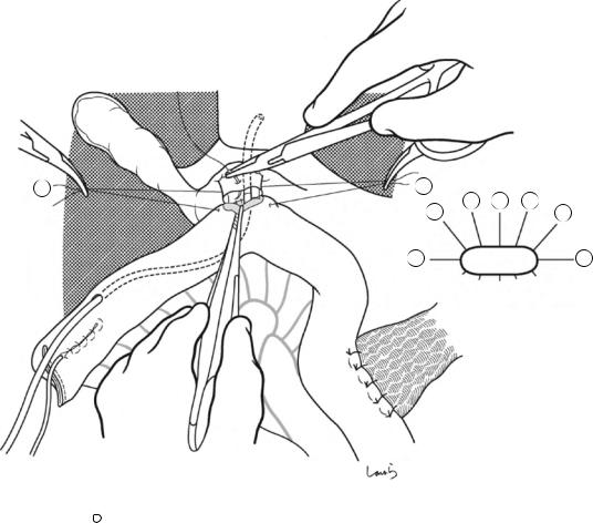
Fig. 18.29 Pancreaticojejunostomy: This should be done |
creatic duct tube is inserted and advanced toward the |
basically by performing pancreatic duct to full-thickness |
jejunal stump and pulled out of the lumen approximately |
jejunum anastomosis. A small incision is placed at the |
3 cm before the stump (the margin for Witzel jejunos- |
planned anastomotic site of the jejunal wall with electro- |
tomy). The other end of the tube is tentatively inserted |
cautery. Through this opening, the guiding part of a pan- |
into the main pancreatic duct by about 5 cm |
18 Pancreaticoduodenectomy: Whipple Procedure |
465 |
|
|
1
3
1
2
2 |
4 |
|
5
4-0 Vicryl suture
Fig. 18.30 Step 1: Suturing of the pancreatic parenchyma. A 4-0 Vicryl suture with straight needles at both ends is passed through the pancreatic parenchyma and the intestinal seromuscular layer in both directions. Although the number of sutures varies depending on the cross- sectional area of the pancreas, for a pancreas of the standard size, two sutures ( 1 and 3 ) should be passed on the cranial and three sutures ( 2 , 4 , and 5 ) should be passed on the caudal sides of the main pancreatic duct. The two closest sutures on both sides of the main pancre-
atic duct should pass as close as possible to, but not through, the duct. The needles should be advanced parallel to the cut surface at a depth of about 5 mm. On the jejunal side, the needles should be inserted according to the shape of the cut surface of the pancreas. After completing this step, a cloth with round holes is placed over the suture threads to prevent them from getting entangled with the suture threads used for subsequent pancreatic duct suturing
466 |
18 Pancreaticoduodenectomy: Whipple Procedure |
|
|
a
3
1
|
4 |
|
5 |
|
|
5-0 PDS |
|
2
4
b
c |
d |
Good suturing
Needle inserted deep in both pancreatic duct and parenchyma
Fig. 18.31 Step 2: Suturing of the pancreatic duct. A 5-0 PDS suture with needles at both ends should be used. After the pancreatic duct tube has been removed temporarily, the first suture is passed through the midpoint of the anterior wall of the duct ( ) and grasped with mosquito forceps without removing the needle (a). With the canopy removed, we have a better operative view. Then, the second suture is passed on the cranial side of the duct ( ) in
Bad suturing
Needle inserted in pancreatic duct but not in pancreatic parenchyma
both directions (i.e., from inside to outside of the pancreatic duct (a) and then from inside to outside of the jejunum) and is grasped with mosquito forceps (b). When suturing the pancreatic duct, the needle should be inserted deep in the duct to ensure that the suture passes through both the duct and pancreatic parenchyma (c). If the needle is inserted shallowly, the suture cannot pass through the pancreatic parenchyma (d)
18 Pancreaticoduodenectomy: Whipple Procedure |
467 |
|
|
1 |
2 |
|
|
|
5 |
|
4 |
|
6 |
|
3 |
3
3 |
6 |
1
Fig. 18.32 The remaining sutures are placed sequentially in the following order: caudal side ( ) and midpoint of the posterior wall ( ), , and . After all sutures have
been passed, sutures , , and are ligated in this order. Sutures and are not ligated yet
468 |
18 Pancreaticoduodenectomy: Whipple Procedure |
|
|
Fig. 18.33 The pancreatic duct tube is inserted and fixed. The depth of insertion into the main pancreatic duct (4–5 cm) should be determined beforehand and that portion of the tube is ligated with a 4-0 Vicryl suture. After the needle has been passed through the jejunal mucosa, the tube is inserted in the main pancreatic duct and the slack of the suture is taken up to make a ligation. This allows for adjusting stent length while ensuring fixation
3
1
2
1
2
4-0 Vicryl suture
3
4-5 cm
2
4
5
4
5
Fig. 18.34 Suture is passed through the jejunum and then additional sutures and are placed, for a total of eight sutures (for a dilated pancreatic duct, more sutures may be added as needed). The sutures on the pancreatic side should be deep enough that the tip of the needle
scratches the tube. Sutures , , , , and are ligated in this order and cut. Make sure that these ligations will not loosen, but at the same time avoid tying them too tight that the pancreatic parenchyma is cut
18 Pancreaticoduodenectomy: Whipple Procedure |
469 |
|
|
Slack of pancreatic duct tube
Purse-string suture
Fig. 18.35 A purse-string 4-0 Vicryl suture is placed at the exit of the pancreatic duct tube from the lifted jejunum, with allowance for the tube to be moderately slack inside the jejunum
Fig. 18.36 Tube jejunostomy is completed using Witzel’s method. The last suture is also passed through the tube to fix it
470 |
18 Pancreaticoduodenectomy: Whipple Procedure |
|
|
1
1
3 |
4 |
|
5
2
5
4
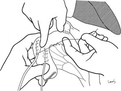
Fig. 18.37 The 4-0 Vicryl sutures passed through the pancreatic parenchyma and the jejunal seromuscular layer are tied. Before tying the sutures, confirm that there is not any slack by pulling both ends of the suture and feeling the amount of force transmitted. Ligations should be made
so that the cut surface of the pancreas and the jejunal wall are in tight contact with each other (i.e., the jejunal wall is pressed against the pancreas). This completes pancreaticojejunostomy
18 Pancreaticoduodenectomy: Whipple Procedure |
471 |
|
|
Pancreatic duct tube
Bile duct tube
Fig. 18.38 Hepaticojejunostomy: A small incision, consistent with the diameter of the hepatic duct, is made at the planned anastomotic site of the jejunal wall with a pointed blade. Through the opening, the guiding part of a bile duct tube is inserted, advanced toward the jejunal stump, pulled
out of the lumen at a point slightly away from the outlet for the pancreatic duct tube, and grasped together with the anastomotic orifice using Satinsky forceps. No bile duct tube is required when a PTCD has been placed or the hepatic duct has a large diameter
472 |
18 Pancreaticoduodenectomy: Whipple Procedure |
|
|
3
1
2
Fig. 18.39 The 4-0 PDS suture with a needle at one end is used. Two sutures are passed through the hepatic duct, from the outside to the inside, and then the jejunum, from inside to outside, at their left and right ends ( and ) and are grasped with mosquito forceps. Another suture ( ) is passed through the midpoint of the posterior wall of the
hepatic duct, from inside to outside, and then the jejunum, from outside to inside. Depending on the diameter of the hepatic duct, more sutures may be added in between as needed. The mosquito forceps are sequentially passed through Kelly forceps to avoid entanglement of the sutures
18 Pancreaticoduodenectomy: Whipple Procedure |
473 |
|
|
1
2 |
|
|
1 |
|
2 |
4 |
|
7 |
5 |
3 |
6 |
|
7
Fig. 18.40 Suture , , , and are passed through the posterior wall of the hepatic duct and tied; the sutures at both ends remain untied. The second assistant should assist by approximating the jejunal limb to the hepatic duct stump
474 |
18 Pancreaticoduodenectomy: Whipple Procedure |
|
|
Fig. 18.41 After the bile duct tube is inserted and fixed in the same fashion as for pancreaticojejunostomy, the anterior wall is sutured ( -12)
18 Pancreaticoduodenectomy: Whipple Procedure |
475 |
|
|
Pancreatic duct tube |
Bile duct tube |
Fig. 18.42 Tube jejunostomy is completed using Witzel’s method. This completes hepaticojejunostomy
476 |
18 Pancreaticoduodenectomy: Whipple Procedure |
|
|
Anastomotic site of hepatic duct and
pancreas
Anal side of jejunum
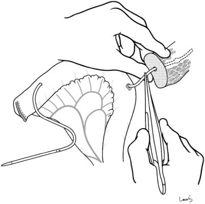
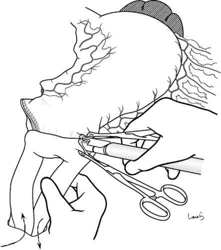
Fig. 18.43 Gastrojejunostomy: A small opening is made on the greater curvature of the remnant stomach 6 cm proximal to the transection line with electrocautery. After the jejunal loop is lifted through another opening made on the transverse mesocolon, the site of anastomosis to the stomach is determined while ensuring a margin for Braun
enteroenterostomy. A small opening is also made on the jejunal loop with electrocautery and an antiperistaltic side-to-side anastomosis is made with a linear stapler (60 mm, blue). The opening for stapler insertion is closed with a 4-0 PDS suture
18 Pancreaticoduodenectomy: Whipple Procedure |
477 |
|
|
Hepaticojejunostomy Pancreaticojejunostomy
Gastrojejunostomy
Braun enteroenterostomy
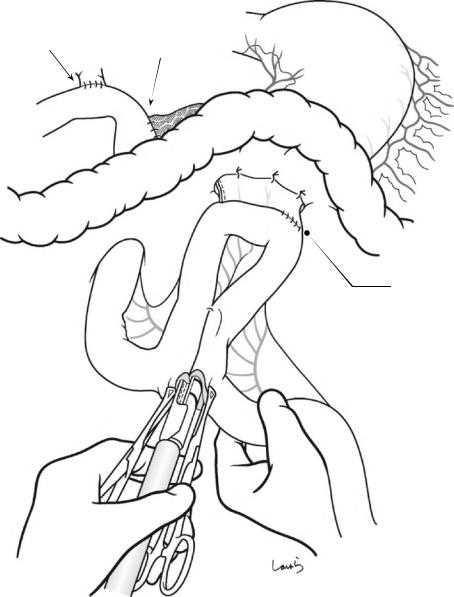
Fig. 18.44 Braun enteroenterostomy: A Braun enteroenterostomy is made with a linear stapler (40 mm, white). The remnant stomach is fixed to the transverse mesocolon
478 |
18 Pancreaticoduodenectomy: Whipple Procedure |
|
|
Bile duct tube
Pancreatic duct tube
Fig. 18.45 The pancreatic and bile duct tubes are pulled out of the abdominal wall and the parts of the jejunal wall around the tube outlets are fixed to the parietal peritoneum. Although by this time you may be very tired and
finding it difficult to concentrate fully, make fine sutures by advancing the needle from back to front while considering the suturing route. The tubes pulled out of the body are further fixed to the skin of the abdominal wall
18 Pancreaticoduodenectomy: Whipple Procedure |
479 |
|
|
Hepaticojejunostomy
Penrose drain tubes (pancreaticojejunostomy site)
Bile duct tube
Pancreatic duct tube
Gastrojejunostomy
Dupe drain tube (hepaticojejunostomy site)
Pancreaticojejunostomy
Braun enteroenterostomy
Fig. 18.46 After washing the abdominal cavity, an 8-mm duple drain tube is inserted from the right abdominal wall and placed under the liver (behind the hepaticojejunostomy site) and two Penrose drain tubes are inserted from
the left abdominal wall and placed behind and in front of the pancreaticojejunostomy site, respectively. The operation is completed by closing the abdominal wall, suturing in three layers. Congratulations, you’re done!
Anatomy of the Inguinal Canal |
19 |
and Surrounding Structures |
Abstract
The inguinal canal is a conduit through which the spermatic cord in men or the round ligament of the uterus in women passes through the abdominal wall. The wall of the inguinal canal is composed of various anatomical components, making it surprisingly difficult to fully understand its threedimensional structure. This chapter intends
to complete the surgical anatomy of the inguinal canal on paper by sequentially attaching the parts that constitute the canal, from inside to outside, viewed from within the abdominal cavity.
Keywords
Inguinal canal · Spermatic cord · Round ligament of the uterus
© Springer Nature Singapore Pte Ltd. 2020 |
481 |
H. Shinohara, Illustrated Abdominal Surgery, https://doi.org/10.1007/978-981-15-1796-9_19 |
|
482 |
19 Anatomy of the Inguinal Canal and Surrounding Structures |
|
|
Aponeurosis of
ext. oblique m.
Rectus abdominis m.
Ant. wall of rectus sheath
 Ext. oblique m.
Linea alba 
Inf. epigastric  a. & v.(divided,*)
Superficial inguinal ring
Ligament of 
Cooper
Lacunar lig.
|
|
Intercrural |
|
||
|
|
fibers |
|
|
|
Medial |
crus |
Lateral |
crus |
||
|
|
|
|
||
|
|
|
|
|
|
|
|
|
|
Deep inguinal ring |
|
|
|
|
|
Fascia transversalis |
|
|
Inguinal lig, |
|
Inf. epigastric a. & v. (*) |
||
|
|
|
|
|
Pre-- |
|
|
|
|
|
peritoneal |
|
|
|
|
|
space |
|
|
|
|
|
|
|
|
|
|
Peritoneum |
|
Bladder
Lateral umbilical lig.
Median umbilical lig.
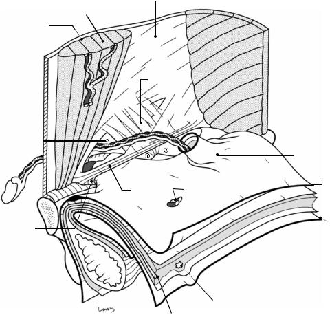
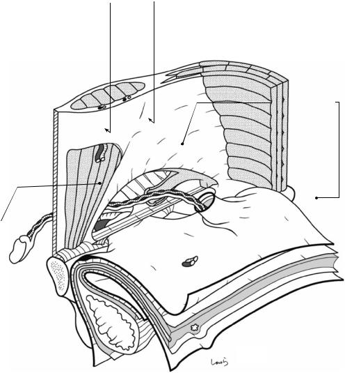
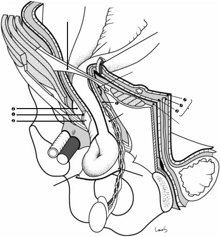
Fig. 19.1 The right inguinal region viewed from the abdominal cavity. As the part closest to the body surface, the external oblique muscle and the rectus abdominis muscle are shown. Under the external oblique muscle are the fascia transversalis, preperitoneal space, and peritoneum, which are illustrated like the unopened pages of a book. The inferior epigastric vessels, which are connected to the external iliac vessels and supply the rectus abdominis muscle, are divided (asterisk). The external oblique muscle continues as an aponeurosis (the external oblique aponeurosis), as shown, and its inner layer forms the anterior wall of the rectus sheath and then fuses with the posterior sheath at the midline to form the linea alba. At the lower border, thickened aponeurotic fibers form the inguinal ligament, with a triangular defect formed above. The two sides of the triangle are referred to as the medial crus and lateral crus, respectively. The body surface side of the defect is covered by the intercrural fibers continuing from the vastus femoris muscle and forming the anterior wall of the inguinal canal; the innermost side of the defect lacks these fibers and instead forms an outlet for the spermatic
cord, the superficial inguinal ring. Although called a “ring,” the superficial inguinal ring has no clear borders because the aponeurotic fibers are partially diffused over the spermatic cord passing through it. A thin membrane is seen continuous from the aponeurotic fibers and covering the surface of the spermatic cord and is referred to as the external spermatic fascia
The inguinal ligament, which is attached to the anterior superior iliac spine and the pubic tubercle, supports the spermatic cord from below and forms the lower wall (floor) of the inguinal canal. Before reaching the pubic tubercle, the inguinal ligament fuses with the periosteum covering the upper border of the superior pubic ramus (the ligament of Cooper) to form the lacunar ligament. The gap between the inguinal ligament and the superior pubic ramus is divided into the vascular lacuna ( ) and the muscular lacuna ( ). The lacunar ligament forms the medial border of the vascular lacuna. The vascular lacuna allows for passage of the femoral artery and vein; the muscular lacuna allows for passage of the iliopsoas muscle and the femoral nerve
19 Anatomy of the Inguinal Canal and Surrounding Structures |
483 |
|
|
Bow-shaped free lower border
Int. oblique m.
Post. wall of rectus sheath
Arcuate line |
Cremaster m. |
Gonadal a. & v. |
Iliac crest |
|
Testis |
. |
Vas deferens
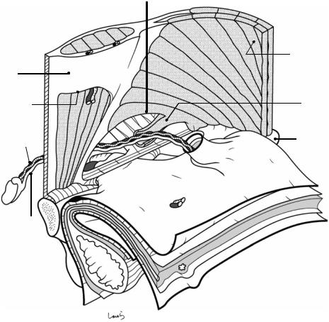
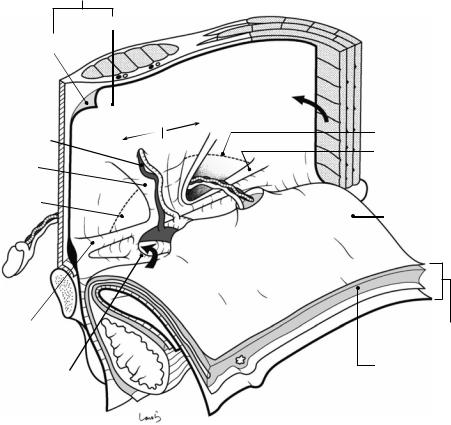
Fig. 19.2 The internal oblique muscle part is attached to the underside of the external oblique muscle. The internal oblique muscle originates from the iliac crest and the lateral side of the inguinal ligament and diffuses while running orthogonal to the external oblique muscle bundle. The muscular part of the muscle extends closer to the rectus abdominis muscle than does the external oblique muscle or the underlying transverse abdominis muscle and forms a bow-shaped free lower border above the spermatic cord, creating the upper wall (ceiling) of the inguinal canal. The lateral end of the attachment of the free lower border is located even more lateral to the triangular defect of the external oblique aponeurosis;
this “displacement” is actually the essence of the inguinal canal. A part of the muscle bundle extends like a tongue and spreads as a thin membrane wrapping around the spermatic cord. This is the cremaster muscle
The narrow aponeurotic part of the internal oblique muscle immediately splits into the anterior and posterior leaves, which become the anterior and posterior walls of the rectus sheath, respectively. The lower part of the posterior sheath is defective and its lower border represents the arcuate line. The area below the arcuate line on the posterior side of the rectus abdominis muscle is where the fascia transversalis will directly attach to
484 |
|
19 Anatomy of the Inguinal Canal and Surrounding Structures |
|
|
|||
Conjoint tendon |
|||
|
|
|
|
|
|
|
|
Aponeurotic arch of |
Free lower border of |
||
transversus abdominis m. |
internal oblique m. |
||
 Transversus m.
Subperitoneal
fascia
Fascia
 transversalis
Femoral sheath
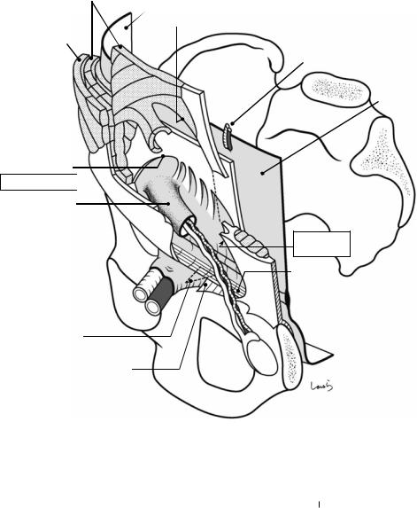
Fig. 19.3 Further attached to the underside of the internal oblique muscle is the transversus abdominis muscle. The muscle bundle of the transversus abdominis is oriented horizontally, although it has already become aponeurotic by the time it reaches the upper part of the inguinal canal. Its lower border also forms an arch and reinforces the corresponding part of the internal oblique muscle from behind, forming the “conjoint tendon.” This is referred to as the aponeurotic arch of the transversus abdominis, but it is structurally difficult to identify from the body surface side. As the aponeurotic arch is almost consistent with the free lower border of the internal oblique muscle, the area bordered by the conjoint tendon (arch) and the inguinal ligament (string) is the weakest part of the abdominal wall,
with no muscle or aponeurosis. This is not because of incomplete development, but rather is a necessary consequence to allow for passage of the spermatic cord. The fascia transversalis, which is to be attached in the next step, is a “lining tissue” that is tightly attached to muscle (aponeurosis) and bone while surrounding the entire abdominal cavity, and in this area, it bears the heavy responsibility of independently supporting the abdominal organs from below. Because the presence of this fascia alone seems inadequate, the aponeurotic fibers of the transversus abdominis are partially dispersed and spread as a thin membrane to reinforce this fascia transversalis (see Fig. 19.5). Having fewer commingled fibers increases the risk of internal inguinal (direct) hernia
19 Anatomy of the Inguinal Canal and Surrounding Structures |
485 |
|
|
Fascia transversalis
Abdominal cavity side
Body surface side
l Latera Medial
Inf. epigastric a. & v.
Interfoveolar lig.
Triangle of
Hesselbach
Deep inguinal ring
Femoral canal
Iliopubic tract
Femoral ring
Line of conjoint tendon
Sling of fascia transversalis
Subperitoneal fascia
Preperitoneal space
Preperitoneal fat
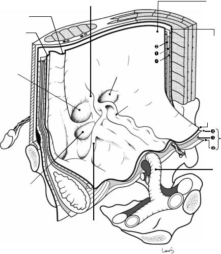
Fig. 19.4 The “page” of the fascia transversalis, the most important structure for understanding the local anatomy of the inguinal region, is flipped and glued to the transversus muscle. There is cord-like thickening of the fascia transversalis parallel to the inguinal ligament, known as the iliopubic tract. The iliopubic tract is connected to the inguinal ligament by the innominate fascia. Beyond the iliopubic tract, the fascia transversalis attaches to the superior pubic ramus while spreading like a fan and covering the ligament of Cooper. Around the vascular lacuna, the fascia cylindrically protrudes by several centimeters while wrapping around the femoral artery and vein, forming the femoral sheath (see Figs. 19.3 and 19.5). During this process, a cone-shaped gap is formed between the femoral vein and the femoral sheath, housing a lymphatic duct, lymph nodes, and fat tissue. This gap is the femoral canal (arrow). The entrance to the femoral canal is referred to as the femoral ring, which serves as the hernial orifice in femoral hernia
The part of the fascia transversalis corresponding to the area bordered by the conjoint tendon and the inguinal ligament (nonglued area) is forced to serve as the posterior wall of the inguinal canal, resisting the intraabdomi-
nal pressure. In this area, a thickened band arises from the midpoint of the iliopubic tract and vertically divides the posterior wall into two parts. This is the interfoveolar ligament and it serves as the base on which the inferior epigastric artery and vein are mounted. The part of the fascia transversalis medial to the interfoveolar ligament lines the triangle of Hesselbach triangle, the hernial orifice of an internal inguinal hernia. The part of the fascia lateral to the ligament protrudes progressively as the peritoneal recess formed in this area deepens, as if wrapping around the recess (see Fig. 19.5). The origin of the protrusion is referred to as the deep inguinal ring and it serves as the hernial orifice of an external inguinal (indirect) hernia. The deep inguinal ring has a V-shaped thickening that resembles the crus of the diaphragm surrounding the esophageal hiatus and is referred to as the sling of fascia transversalis. In response to increased intraabdominal pressure, the crus of the sling is closed by a shutter mechanism to prevent the development of external inguinal hernia. The interfoveolar ligament and the sling represent the maximum effort made by the fascia transversalis, which was surprisingly assigned the responsibility of supporting the abdominal organs
486 |
19 Anatomy of the Inguinal Canal and Surrounding Structures |
|
|
Int. oblique m.
Fascia transversalis (abdominal cavity side)
Free lower border of internal oblique m.
Ext. oblique m.
Cremaster m. 
Aponeurotic arch of transversus abdominis m.
Deep inguinal ring 
Int. spermatic fascia
Aponeurosis  Femoral sheath
Femoral a. & v. 
Femoral canal
Inf. epigastric a. & v.
Fascia transversalis (body surface side)
Aponeurotic fibers of  transversus abdominis m.
spreading over surface of fascia transversalis
Superficial inguinal ring
Inguinal lig.
 Iliopubic tract
 Ligament of Cooper
Lacunar lig.
Fig. 19.5 Now that the fascia transversalis has been attached, all of the members that constitute the inguinal canal are in place. Before flipping the pages of the preperitoneal space and the peritoneum, let us review the parts assembled so far from the outside of the abdominal wall
The “anterior wall” of the inguinal canal consists of the aponeurosis of the external oblique muscle and intercrural fibers; the “upper wall” consists of the conjoint tendon formed by the free lower border of the internal oblique muscle and the aponeurotic arch of the transversus muscle; the “posterior wall” consists of the fascia transversalis and part of the aponeurotic fibers of the transversus muscle; and the “lower wall” consists of the inguinal ligament. The free lower border of the internal
oblique muscle is slid upward in the figure to help understand that the free lower border forms the upper wall of the inguinal canal. From this figure, we can see that the “displacement” between the defect of the external oblique aponeurosis and the conjoint tendon creates the inguinal canal and enables the deep and superficial inguinal rings
to be positioned in a “ ” shape. Note that this “displacement” increases with physical growth, so the deep inguinal ring in neonates is located immediately posterior to the superficial inguinal ring, forming a short inguinal canal. The part of the fascia transversalis that protrudes like a finger cot is now referred to as the internal spermatic fascia and covers the spermatic cord. This is further wrapped around by the cremaster muscle, which is a part of the internal oblique muscle bundle
19 Anatomy of the Inguinal Canal and Surrounding Structures |
487 |
|
|
Lat. umbilical fold |
Peritoneum |
Med. umbilical fold
Med. umbilical fold
|
Fascia transversalis |
Med. inguinal fossa |
Lat. inguinal fossa |
|
|
|
Testicular a. & |
|
v. (folds) |
|
Peritoneum |
|
Preperitoneal |
|
space |
|
Ext. iliac a. & v. |
Femoral fossa |
|
|
Vas deferens (folds) |
Fig. 19.6 Finally, the preperitoneal space and the peritoneum are attached. The preperitoneal space, which is also mentioned in Chap. 1 on the anatomy of the stomach and Chap. 8 on the anatomy of the large intestine, has a three- layered structure where the intermediate fat layer ( ) is sandwiched between two thin layers of subperitoneal fascia ( ). Although due to its structure we might feel uncomfortable to call it a “space,” the fat layer is much looser and softer than subcutaneous fat. As described in Chap. 1, the term “preperitoneal space” is based on the observation from the body surface side and the same space is called the “retroperitoneal space” when viewed from within the abdominal cavity. Similarly, the soft fat issue referred to as “preperitoneal fat” in this chapter is called “extraperitoneal fat” when viewed from within the abdominal cavity. The preperitoneal space allows for passage of the vas deferens, testicular artery and vein, lateral umbilical ligament (remnant of the umbilical artery connected to the superior vesical artery), and the median umbilical ligament (remnant of the urachus). Along the lateral and median umbilical ligaments are cord-like bulgings of the peritoneum referred to as the medial and median umbilical folds, respectively. The inferior epigas-
tric vessels, which are connected to the external iliac vessels, do not pass through the preperitoneal space but pass in front of the fascia transversalis, which is the next shallower layer when viewed from the body surface (see Fig. 19.4). Along these vessels is also a cord-like bulging of the peritoneum referred to as the lateral umbilical fold. The part of the peritoneum lateral to the lateral umbilical fold corresponding to the deep inguinal ring forms a recess, the lateral inguinal fossa, which is where external inguinal hernia develops. On the medial side of the lateral umbilical fold, the part of the peritoneum corresponding to the triangle of Hesselbach also forms a recess, the medial inguinal fossa, which is where internal inguinal hernia develops. The inferior epigastric vessels form a partition between the internal and external inguinal fossae, which can be a useful landmark for distinguishing between external and internal inguinal hernias. The parts of the peritoneum lining the femoral ring also form a recess, the femoral fossa, which is where femoral hernia develops. Because these three fossae are located close to each other and serve as the orifices for all types of hernia occurring in the inguinal region, they are collectively referred to as the “myopectineal orifice of Fruchaud”

488 |
19 Anatomy of the Inguinal Canal and Surrounding Structures |
||||||
|
|
|
|
|
|
|
|
Peritoneum |
|
|
|
|
|
|
|
Preperitoneal |
|
|
|
|
|
|
|
space |
|
|
|
|
|
|
|
Fascia transversalis |
Inf. epigastric a. & v. |
|
|
|
|
||
|
|
|
|
|
|
|
|
|
|
Interfoveolar lig. |
Lat. umbilical lig. |
|
|
||
|
Ext. inguinal hernia |
|
|
||||
|
|
|
|
|
|
Med. umbilical lig. |
|
|
|
|
|
|
|
||
|
|
|
Int. inguinal hernia |
|
|||
|
|
|
|
|
|
||
Aponeurotic arch of |
|
|
|
|
|
|
|
|
|
|
|
|
|
|
|
transversus abdominis m. |
|
|
|
|
|
|
|
Int. oblique m.
 Cremaster m.
Ext. oblique aponeurosis
 Ext. spermatic fascia
 Int. spermatic fascia
Vestigial processus vaginalis peritonei
Visceral laminae
Tunica vaginalis
Parietal laminae
Rectus sheath
 Vas deferens Gonadal a. & v.
Testis
Scrotal cavity
Fig. 19.7 Structure of inguinal hernia in a cross section of the spermatic cord: During fetal life, when the testis that forms in the extraperitoneal fat tissue (preperitoneal fat tissue) of the retroperitoneal space (preperitoneal space) begins its descent, a peritoneal recess is formed at the susceptible part of the abdominal wall lateral to the interfoveolar ligament. This recess gradually deepens while acquiring, but not rupturing, the layers constituting the preperitoneal space [preperitoneal fat tissue ( ) + two thin layers of subperitoneal fascia ( )] and the fascia transversalis ( ), that is, while being wrapped around by this multilayer structure, and extends into the inguinal canal. This structure is referred to as the “processus vaginalis” (the term “processus vaginalis peritonei” indicates only its peritoneal component). After confirming that the processus vaginalis has reached the scrotum, the testis, guided by the gubernaculum, descends gradually within the preperitoneal fat layer ( ) from which it originally arises, accompanied by the vas deferens and testicular vessels, until it reaches its final position at the lower end of the processus vaginalis. This path is always located posterior to (on the abdominal wall side of) the processus vaginalis, either inside the inguinal canal or in the scrotum. After the passage of the testis, this “processus vaginalis with a multi-layered wall containing the vas deferens and testicular vessels” becomes the “spermatic cord.” The spermatic cord is covered by a fascia that is continuous with the fascia transversalis ( ) arising from
the deep inguinal ring, that is, the internal spermatic fascia ( ′). While passing through the inguinal canal, the spermatic cord also acquires a part of the muscle bundle forming the lower border of the internal oblique muscle and takes it away. This becomes the cremaster muscle ( ), which further wraps around the spermatic cord and forms its outermost layer. Once out of the inguinal canal, the spermatic cord is sequentially covered by the external spermatic fascia (continued from the external oblique aponeurosis; ), which it acquired while passing through the superficial inguinal ring, the dartos muscle continuous with the subcutaneous superficial fascia, and the scrotal skin
The innermost layer of the spermatic cord is, needless to say, the peritoneum, which persists as the tunica vaginalis testis only at the tip of the cord and degrades or disappears in other parts. Any persistent peritoneum can form a hernia sac of pediatric external inguinal hernia. The residual tunica vaginalis forms the scrotal cavity, which is composed of the visceral and parietal laminae and filled with serous fluid. In certain conditions, the scrotal cavity is filled with pathological serous effusion and is distended, and this is referred to as hydrocele
The hernia sacs in adult external inguinal hernia (black arrow) and internal inguinal hernia (white arrow) are formed by sac-like extensions of the peritoneum at the external and internal inguinal fossae, respectively, with the layers of the preperitoneal space remaining intact
19 Anatomy of the Inguinal Canal and Surrounding Structures |
489 |
|
|
Aponeurotic arch of transversus abdominis m.
Int. epigastric a. & v.
 Int. spermatic fascia
 Cremaster m.
 Peritoneum
 Internal spermatic fascia
Preperitoneal space
Peritoneum
 Fascia transversalis
Peritoneum 

 Femoral sheath
Small intestine
Fig. 19.8 The right abdominal wall again viewed from the body surface side, showing the three-dimensional structure of external inguinal hernia. The spermatic cord is surrounded by two layers: the cremaster muscle ( ) derived from the internal oblique muscle and the internal spermatic fascia ( ′) derived from the fascia transversalis. Between the hernia sac formed by a stretched peritoneum and the internal spermatic fascia are preperitoneal fat tissue ( ) and two thin layers of subperitoneal fascia ( ). The vas deferens and testicular vessels course through the preperitoneal fat layer on the abdominal wall
side. The femoral sheath ( ″), which appeared earlier (Fig. 19.4), is also formed by the cylindrical extension of the fascia transversalis ( ), just like the internal spermatic fascia
In women, ovarian descent stops when a part of the gubernaculum attaches to the uterus. The part of the gubernaculum between the uterine wall and the labium majus persists as the round ligament of uterus, and the structures corresponding to the internal spermatic fascia ( ′), cremaster muscle ( ), and external spermatic fascia ( ) in men all become the capsule of the ligament
490 |
19 Anatomy of the Inguinal Canal and Surrounding Structures |
|
|
a |
Inf. epigastric a. & v. |
|
|
|
|
|
Hernia sac (blind end) |
|
Vas deferens |
|
|
|
|
|
|
|
Gonadal a. & v. |
|
|
|
|
|
|
* |
|
|
Inverted hernia sac |
|
|
b |
Plug |
|
|
Onlay mesh
Slit

19 Anatomy of the Inguinal Canal and Surrounding Structures |
491 |
|
|
|
|
|
|
|
Fig. 19.9 Here, we look at the typical procedures for repairing external inguinal hernia, using the same cross- sectional diagram as that in Fig. 19.7
The part of the spermatic cord indicated by an asterisk in (a) is the normal structure. It has a folded double structure like folded strata of earth and consists of, in the order of encounter when entering from the outermost layer through the core and then out through the other side of the cord, the following 11 layers in total: the cremaster muscle, internal spermatic fascia ( ′), subperitoneal fascia ( ), preperitoneal fat tissue ( ), subperitoneal fascia ( ), vestigial processus vaginalis peritonei, subperitoneal fascia ( ), preperitoneal fat tissue containing the vas deferens and testicular vessels ( ), subperitoneal fascia ( ), internal spermatic fascia ( ′), and cremaster muscle
Higher ligation (a): First, the cremaster muscle ( ) is cut off from the free lower border of the internal oblique muscle and the spermatic cord is circumferentially isolated inside the inguinal canal. After the internal spermatic fascia ( ′) is circumferentially incised at the origin of the spermatic cord to open the deep inguinal ring, the two layers of the subperitoneal fascia ( ) are incised so that the hernia sac can be reached. The hernia sac is then tran-
sected and ligated, leaving only the vas deferens and testicular vessels exposed
Mesh plug repair (b): A plug is inserted while inverting the hernia sac. After the vas deferens and gonadal vessels are allowed to pass through the slit of an onlay mesh, the mesh is placed in front of the plug and the fascia transversalis ( ) to reinforce the posterior wall
Repair using the Prolene Hernia System (c): After ligation of the hernia sac, the peritoneum and the subperitoneal fascia ( ) of the preperitoneal space are separated to create a wide gap. A connector is placed in the deep inguinal ring and an underlay patch is inserted into the gap created. This patch is located deeper than the inferior epigastric vessels and vas deferens and testicular vessels. The vas deferens and testicular vessels are allowed to pass through a slit created on the onlay patch, and then the patch is placed in front of the fascia transversalis ( ) to reinforce the posterior wall
Direct Kugel repair (d): As for Prolene Hernia System repair, the peritoneum and subperitoneal fascia ( ) of the preperitoneal space are separated broadly to create a gap and an underlay patch is inserted into the gap. In this figure, the hernia sac is inverted into the abdominal cavity without being transected
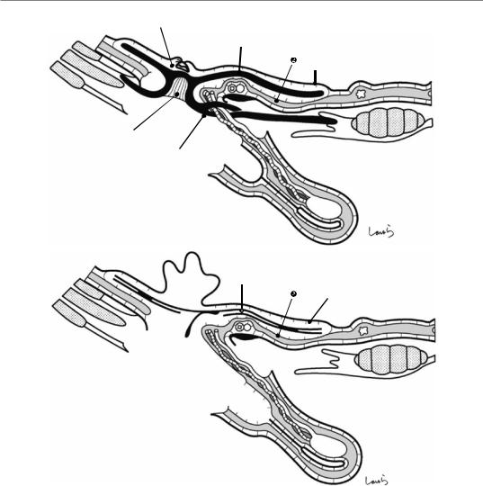
492 19 Anatomy of the Inguinal Canal and Surrounding Structures
c |
Ligated hernia sac |
|
|
|
Underlay patch |
|
Peritoneum |
Connector
Onlay patch
d |
Inverted hernia sac |
|
Underlay patch |
Peritoneum
Fig. 19.9 (continued)
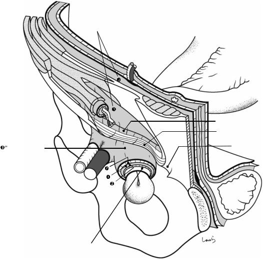
19 Anatomy of the Inguinal Canal and Surrounding Structures |
493 |
|
|
Fascia transversalis
 Int. spermatic fascia
Iliopubic tract
Inguinal lig.
Femoral sheath |
Lacunar lig |
|
Small intestine
Hernia sac (peritoneum)
Fig. 19.10 Structure of a femoral hernia. While covered by the stretched femoral sheath ( ″) and subperitoneal fascia ( ), the hernia sac (peritoneum) passes through the femoral canal into the fossa ovalis. Because the femoral ring that serves as the hernia orifice is composed of the robust inguinal and lacunar ligaments, the hernia tends to
be incarcerated. When the hernia contents cannot be pushed back into the abdominal cavity, we need either to widen the femoral canal by incising the lacunar ligament or, if that is not sufficient, to open the femoral canal by also incising the inguinal ligament
Plug |
20 |
Repair of Inguinal Hernia: Mesh |
|
Abstract
Just like with film production, several staff members participate in an operation, such as anesthesiologists, instrument and circulating nurses, and surgeons. If we think of the lead actor of an operation as the operating surgeon, then the role of the movie director—who gives the lead actor detailed instructions on movement, controls the overall progress, and prepares a comfortable work environment for everyone participating while paying attention to the surroundings—should, I believe, be played by the first assistant. Even in small operations such as inguinal hernia repair, the role expected of the first assistant is always the same: to maintain a good operative field. In
this operation especially, we can see impressive multilayered fascial structures. The surgeon can enjoy the procedure by dissecting the layers wrapping around the spermatic cord one by one while also thinking about how the cord was formed during fetal life. Due to very few anatomical variations, we can be confident in performing this operation after performing several procedures carefully supervised by senior surgeons. This chapter describes a repair procedure using a mesh plug. The operation time is about 40 min.
Keywords
Operating surgeon · First assistant · Mesh plug · Inguinal hernia repair
© Springer Nature Singapore Pte Ltd. 2020 |
495 |
H. Shinohara, Illustrated Abdominal Surgery, https://doi.org/10.1007/978-981-15-1796-9_20 |
|
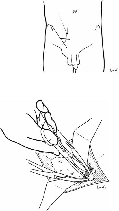
496 |
20 Repair of Inguinal Hernia: Mesh Plug |
|
|
Sup. epigastric v.
Fig. 20.1 From the midpoint of a line connecting the anterior superior iliac spine and the superficial inguinal ring, a skin incision about 6 cm long is made medially along the line of Langer
Sup. epigastric v.
Fig. 20.2 The first assistant expands the wound with two flat retractors. The superficial epigastric vein is usually encountered as it crosses the wound. The vein should be
coagulated with electrocautery if it is thin, or ligated and divided if it is thick
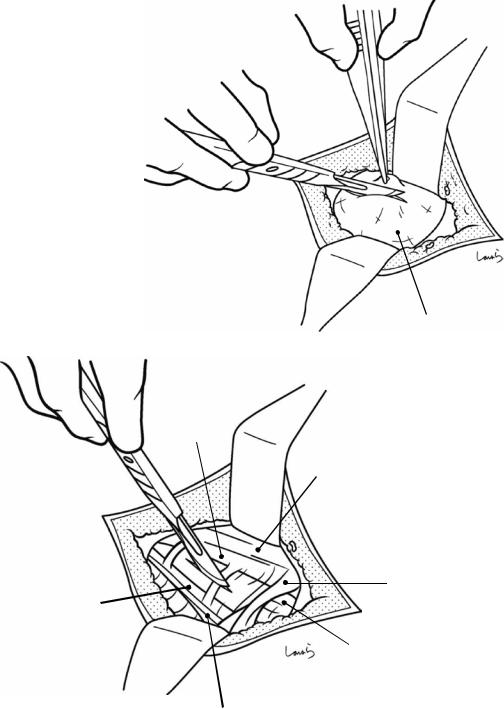
20 Repair of Inguinal Hernia: Mesh Plug |
497 |
|
|
Fig. 20.3 Two thin layers of the superficial fascia must be passed before reaching the external oblique aponeurosis. The dissection should then continue by picking them up with hooked forceps and dividing them with a scalpel
Superficial fascia
Medial crus
Aponeurosis of ext. oblique m.
Sup. inguinal ring
Lateral crus
Spermatic cord
(ext. spermatic fascia)
Inguinal lig.
Fig. 20.4 After exposing the pearl-colored fibers of the external oblique aponeurosis, the operative field should be expanded adequately with retractors. The triangle formed between the lateral crus and medial crus (covered by the intercrural fiber, through which the brownish cremaster muscle can be seen) and the superficial inguinal ring
(located on the line extended from the triangle) should be identified accurately. If we fail to do this, we will get lost in a maze. Within the triangle, a small incision is made along the fibers of the external oblique aponeurosis. The incision should be shallow enough to avoid damaging the nerves and vessels in the spermatic cord
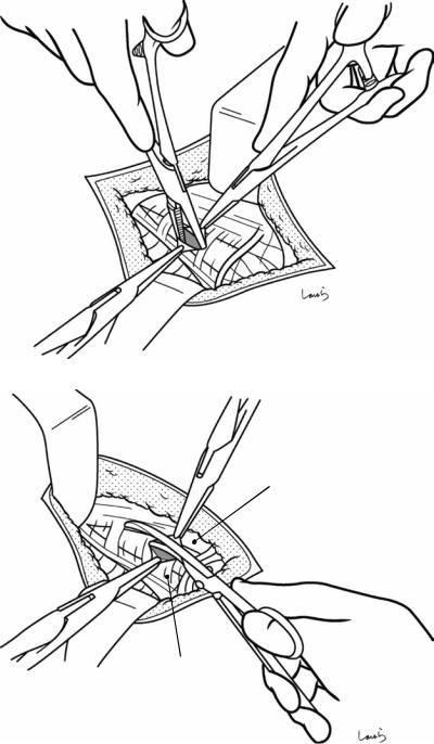
498 |
20 Repair of Inguinal Hernia: Mesh Plug |
|
|
Fig. 20.5 The edge of the incision is grasped with Pean forceps. For easy grasping, try inserting the forceps into the incision and open them while lifting up, which lifts the aponeurosis from the spermatic cord
Cremaster m. 
Fig. 20.6 The incision is extended with Mayo scissors along the direction of the fibers up to the vicinity of the deep inguinal ring and grasped with another pair of Pean forceps. During this procedure, be careful not to damage the ilioinguinal nerve coursing immediately below the aponeurosis (Fig. 20.8)
Lateral crus
Medial crus
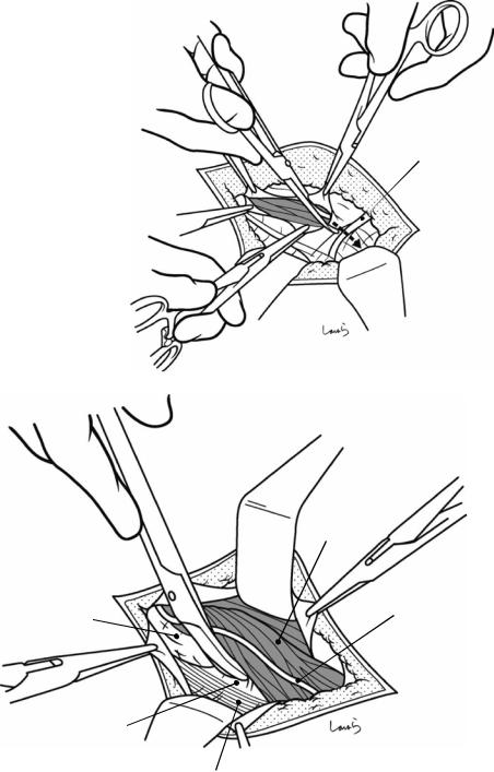
20 Repair of Inguinal Hernia: Mesh Plug |
499 |
|
|
Fig. 20.7 The incision is then also advanced toward the outlet for the spermatic cord. The external spermatic fascia, which continues from the superficial inguinal ring, is partially incised to open the inguinal canal completely. This exposes the cremaster muscle covering the surface of the spermatic cord
Spermatic cord (Int. spermatic fascia)
Fascia transversalis
Sup. inguinal ring
 Ext. spermatic fascia
Cremaster m.
Ilioinguinal n.
Inguinal lig.
Fig. 20.8 Now the spermatic cord is isolated. First, the cord is detached from the lower wall of the inguinal canal. The spermatic cord is bluntly detached from the external oblique aponeurosis and the inguinal ligament with the tip of Cooper scissors. Usually, the cord can be detached eas-
ily with no adhesions. The dissection should advance beyond the pearl-colored inguinal ligament until reaching the fascia transversalis that forms the posterior wall of the inguinal canal. This helps with the later lifting of the spermatic cord
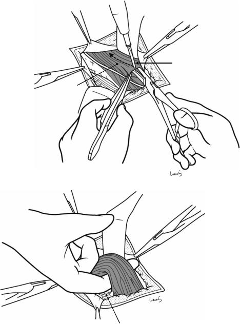
500 |
20 Repair of Inguinal Hernia: Mesh Plug |
|
|
Fig. 20.9 Next, the |
|
cord is detached from |
|
the upper wall of the |
|
inguinal canal. On this |
|
side, unlike the lower |
|
wall side, the spermatic |
|
cord is linearly |
|
connected to the internal |
|
oblique muscle via the |
Int. oblique m. |
cremaster muscle. The |
|
internal oblique muscle |
|
is exposed widely by |
|
applying force to the tip |
Cremaster m. |
of the proximal flat |
|
retractor, and the |
|
junction with the |
|
cremaster muscle is |
|
divided with |
|
electrocautery. (The |
|
internal oblique muscle |
|
should be exposed at |
|
this point because it will |
|
be needed later for onlay |
|
mesh insertion) |
|
Pubic tubercle
Fig. 20.10 After detaching the spermatic cord from the upper and lower walls, the index finger is slid under the cord. For an external inguinal hernia, the cord will be thickened by the presence of the hernia sac, so the index finger should be inserted deep enough to be scooped the entire cord. For an internal inguinal hernia, a loosened
posterior wall (fascia transversalis) means that it is difficult to find the correct route to insert the index finger. Also, note that inserting the finger too deeply can damage the hernia sac. To be safe in either case, insert the index finger along the pubic tubercle
20 Repair of Inguinal Hernia: Mesh Plug |
501 |
|
|
Cremaster m.
Int. spermatic fascia
Ilioinguinal n.
Fascia transversalis
Fig. 20.11 The inserted finger is then slid horizontally to thoroughly detach the spermatic cord from the posterior wall. A pair of Kelly forceps is then passed under the cord, guided by the finger, to grasp a thin Nelaton catheter with its tip and pull it out. The catheter is formed into a loop
and grasped with Kocher forceps. The detached spermatic cord is surrounded by the cremaster muscle and the internal spermatic fascia, which continues from the fascia transversalis and is mounted by the ilioinguinal nerve
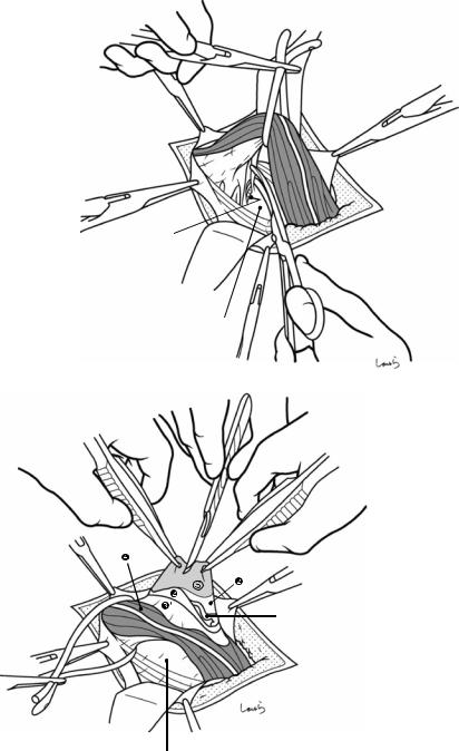
502 |
20 Repair of Inguinal Hernia: Mesh Plug |
|
|
Fig. 20.12 With the spermatic cord lifted using the Nelaton catheter, the residual fibrous connective tissue between the cord and the posterior wall is dissected to complete spermatic cord isolation. Proceeding with the dissection up to the vicinity of the deep inguinal ring enables us to identify the inferior epigastric vessels. For an internal inguinal hernia, the hernia sac can be seen at this point
Inf. epigastric a. & v.
Fascia transversalis
Vas deferens and gonadal a. & v.
 Fascia transversalis
Fig. 20.13 Handling of a large hernia sac (Figs. 20.13– 20.20): In mesh plug repair, the hernia sac is usually not resected and inverted into the abdominal cavity. However, a large hernia sac that protrudes beyond the midpoint of the inguinal canal should be transected at an appropriate point. The standard procedure is to identify the hernia sac around the midpoint of the spermatic cord and detach it from the cord. To reach the hernia sac ( ) from the surface of the spermatic cord, we need to pass through the cre-
master muscle ( ), internal spermatic fascia ( ′), and the two thin layers of the subperitoneal fascia ( )in that order. Using two pairs of hooked forceps, these structures are sequentially identified and divided, and a whitish hernia sac is withdrawn from underneath them. The surgeon asks the first assistant to make a small incision on the sac and examine the inside. The hernia sac can either be identified at a glance by its whitish thickened wall or it may have a thin wall that makes it difficult to identify

20 Repair of Inguinal Hernia: Mesh Plug |
503 |
|
|
Fig. 20.14 Grasping the edge of the incised opening with two pairs of Pean forceps, the incision is extended proximally and distally with Mayo scissors. Proximally, only a short incision should be made, and the edge grasped
Fig. 20.15 Appearance of the hernia sac ( ) after it has been opened.′, internal spermatic fascia
with Pean forceps. In contrast, the distal incision should be extended as far as it can be, even up to the blind end if it can be identified
y |
|
Abdominal |
|
cavit |
Blind |
|
|
end |
|
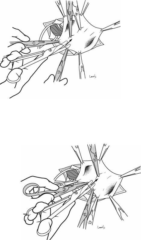
504 |
20 Repair of Inguinal Hernia: Mesh Plug |
|
|
Fig. 20.16 Transection of the hernia sac (the subsequent procedures are not necessary if the sac forms a blind end in the inguinal canal): The hernia sac is transected while being supported with three pairs of Pean forceps. Forcepsand are applied first. Forceps is also applied on the transection line to minimize the cutting distance. While
Fig. 20.17 Forceps is applied and the hernia sac is detached and divided while being supported with forceps, , and
applying countertraction with forceps , , and , Mayo scissors are slid under the sac to cut just the sac while detaching the other tissues, such as the vas deference and blood vessels. For better handling of scissors, it is advisable to use the “open while advancing” technique
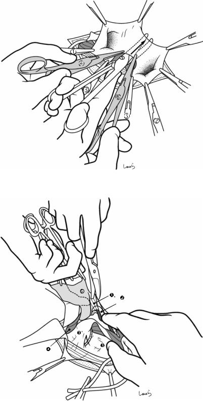
20 Repair of Inguinal Hernia: Mesh Plug |
505 |
|
|
Fig. 20.18 Finally, forceps is applied and the transection of the hernia sac is complete. The forceps applied to the distal part of the sac are removed, leaving that part of the sac as it is
Fig. 20.19 The hernia sac is then detached from the spermatic cord toward the deep inguinal ring. Lifting the sac up with the left index finger inserted into the sac, tissues surrounding the sac (the layers of the preperitoneal space, including the preperitoneal fat tissue containing the vas deferens and testicular vessels and the subperitoneal fascia ) are peeled off with Cooper scissors. This should be done carefully to avoid damaging the vas deferens or blood vessels or perforating the sac. The first assistant pulls the spermatic cord downward to apply tension to the dissected part
Vas deferens
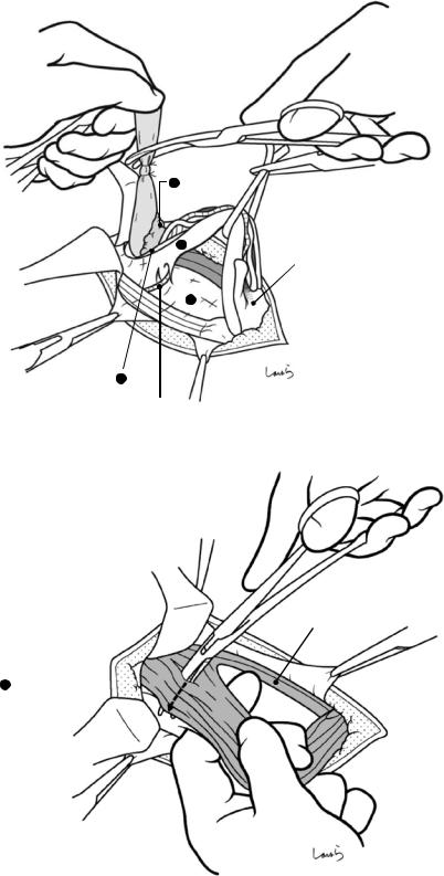
506 |
20 Repair of Inguinal Hernia: Mesh Plug |
|
|
Fig. 20.20 As the hernia sac is lifted from the spermatic cord, the internal spermatic fascia and the subperitoneal fascia covering the cord are spontaneously torn longitudinally. Continuing this procedure ends up reaching the junction with the fascia transversalis, that is, the deep inguinal ring. Detachment of the hernia sac is complete when the prominent hump of the preperitoneal fat tissue is exposed at the root of the sac. The hernia sac is divided far enough from the root for the later insertion of a plug and inversion of the sac (about 3 cm). The proximal stump is closed by piercing ligation with a 3-0 Vicryl suture
Fig. 20.21 Handling of a small hernia sac
(Figs. 20.21–20.24): In the case of a mild hernia, we need to explore the vicinity of the deep inguinal ring to identify the hernia sac. But we must be careful because damaging the hernia sac at this level could cause us to get lost in a maze and make repair difficult. So, we need to proceed with the dissection carefully while accurately identifying each layer. First, the outermost cremaster muscle is scooped superficially with dissection forceps along the short axis of the muscle and divided with electrocautery. (If identifiable, the ilioinguinal nerve coursing over the cremaster muscle should be preserved whenever possible)
1Preperitoneal
fat tissue
3 ′
Distal stump of hernia sac
3
2
Inf. epigastric a. & v.
Inf. oblique m.
4 Cremaster m. 
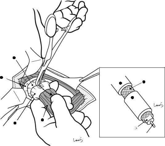
20 Repair of Inguinal Hernia: Mesh Plug |
507 |
|
|
2
3
3 |
2 |
|
3 ′
4
3 ′
Hernia contents (small intestine)
Fig. 20.22 The next step is to circumferentially incise the internal spermatic fascia ( ′) where it arises from the fascia transversalis ( ). This is just like making a circumferential cut into the vinyl sheath of a coaxial cable leading to an antenna. This makes a round opening on the
fascia transversalis along the deep inguinal ring and exposes the inferior epigastric vessels inside the ring. A longitudinal incision is also made along the long axis of the spermatic cord on the internal spermatic fascia up to the midpoint of the cord
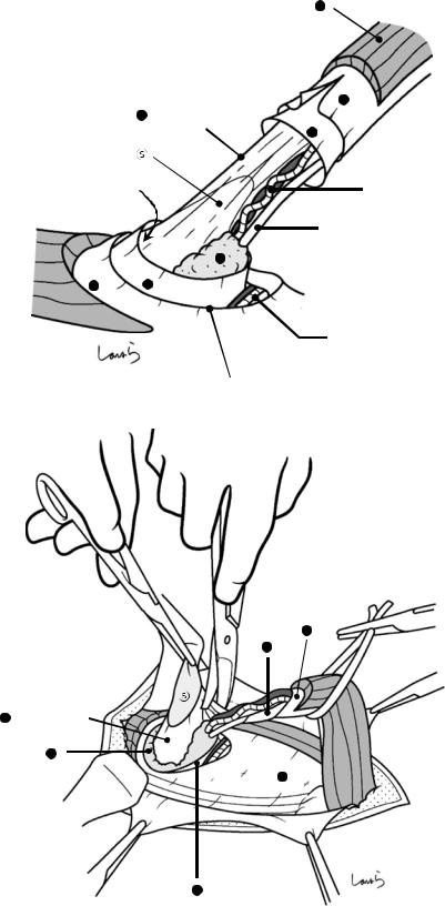
508 |
20 Repair of Inguinal Hernia: Mesh Plug |
|
|
Fig. 20.23 At this point, the outermost layer of the spermatic cord is the superficial subperitoneal fascia ( ). By incising this membrane, we can enter the space that continues from the preperitoneal space and this reveals the preperitoneal fat tissue ( ). As the incision continues, the vas deferens and testicular vessels are also exposed. By this time, a white hernia sacthat is distinct from other membranes can be seen transparently. The hernia sac is overlaid by another (deep) layer of the subperitoneal fascia ( ). Once the sac is identified, a part of the sac is grasped together with the subperitoneal fascia using Pean forceps and pulled up.′, internal spermatic fascia; , cremaster muscle
Fig. 20.24 The hernia sac ( ) is then lifted from the spermatic cord by peeling off the deep subperitoneal fascia covering the sac ( ) with Cooper scissors. If the hernia sac is firmly adherent to the subperitoneal fascia, we must be careful to avoid forcibly detaching the fascia, which risks damaging the sac. All we need to do is separate the hernia sac from the vas deferens and testicular vessels so that it can be inverted properly. However, when we plan to repair using the Prolene Hernia System or a direct Kugel repair, we must peel off all layers other than the peritoneum from the hernia sac so that we can correctly enter the preperitoneal space (the gap between the peritoneum and the subperitoneal fascia), into which an underlay patch will be inserted
4
|
3 ′ |
2 |
(Deep layer) |
|
2 |
Space continuing from |
Gonadal a. & v. |
preperitoneal space |
|
|
Vas deferens |
1
3 2
Inf. epigastric a. & v.
Deep inguinal ring
3 ′
2
2 (Deep layer)
1
3
2
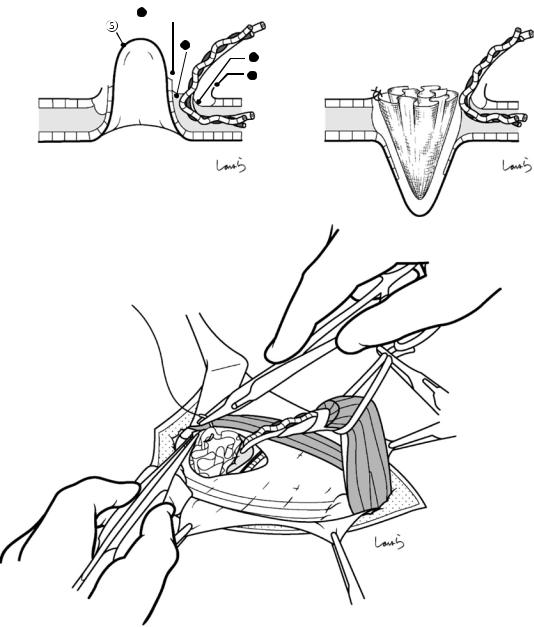
20 Repair of Inguinal Hernia: Mesh Plug |
|
509 |
|
|
|
|
|
a |
2 (Deep layer) |
|
b |
|
1 |
|
|
|
2 |
(Deep layer) |
Plug |
|
3 |
|
|
|
|
|
|
Inverted hernia sac
c
Fig. 20.25 The isolated hernia sac is then inverted into the abdominal cavity (a) and a plug is inserted into the inverted sac (b). The fascia transversalis around the deep inguinal ring and the plug are fixed by using two 3-0 Vicryl sutures (c)
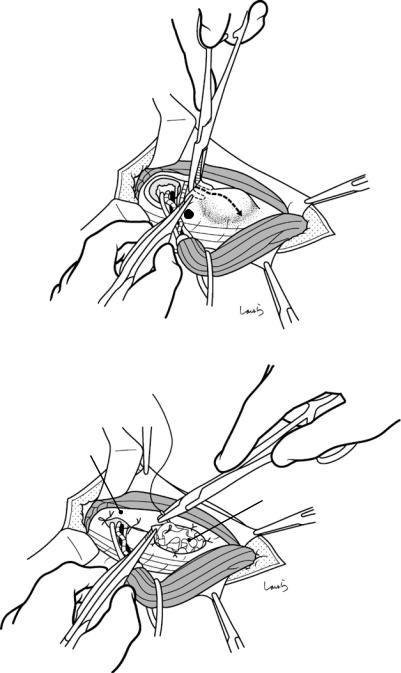
510 |
20 Repair of Inguinal Hernia: Mesh Plug |
|
|
Fig. 20.26 Plug insertion for internal inguinal hernia: An internal inguinal hernia should be suspected when, after the spermatic cord has been isolated and lifted up, the posterior wall of the inguinal canal appears loose and fragile and the spermatic cord appears thinner than usual. Also in this case, the deep inguinal ring should be incised by following the procedure in Figs. 20.21–20.23 to confirm the absence of a hernia sac lateral to the inferior epigastric vessels. Then, the fascia transversalis is cut off the periphery of the deep inguinal ring by making an incision parallel to the inguinal ligament (a). After identifying the hernia sac medial to the inferior epigastric vessels, the sac is inverted into the abdominal cavity and a plug is inserted into the inverted sac. The edge of the fascia transversalis and the plug are fixed using several 3-0 Vicryl sutures (b). The incised deep inguinal ring should be repaired by applying two sutures to the fascia transversalis, one at the medial end and the other at the lateral end of the ring. We may also encounter cases of internal inguinal hernia where the entire posterior wall of the inguinal canal has become a hernial orifice and there is no “sac” into which a plug can be inserted. , fascia transversalis
a
3
b
Sutured inguinal ring
Plug
20 Repair of Inguinal Hernia: Mesh Plug |
511 |
|
|
Fig. 20.27 Placement of onlay mesh: After the vas deferens and testicular vessels are passed through the slit on the mesh, the slit is closed with two 3-0 Vicryl sutures
Fig. 20.28 The mesh is spread over the posterior wall of the inguinal canal, with the cranial side oriented in front of the internal oblique muscle. To prevent the mesh from displacing, its upper and lower corners are anchored to the internal oblique muscle and the inguinal ligament, respectively, using 3-0 Vicryl sutures
Int. oblique m.
Inguinal lig.
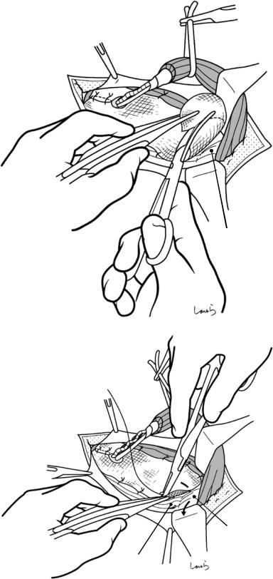
512 |
20 Repair of Inguinal Hernia: Mesh Plug |
|
|
Fig. 20.29 After several additional sutures are applied to the internal oblique muscle and the inguinal ligament for mesh fixation, the excess portion on the lower end of the mesh on the pubic tubercle is cut off
Fig. 20.30 The inguinal ligament fuses with the periosteum covering the upper border of the superior pubic ramus (the ligament of Cooper) to form the lacunar ligament and is attached to the pubic tubercle (see Fig. 19.1 on the anatomy of the inguinal canal and surrounding structures). The lower end of the mesh is firmly fixed to the lacunar ligament with two to three sutures. This is the most important procedure in preventing postoperative recurrence
Pubic tubercle
Pubic tubercle
Lacunar lig.
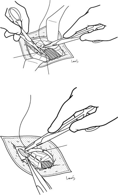
20 Repair of Inguinal Hernia: Mesh Plug |
513 |
|
|
Fig. 20.31 The testis is pulled down to stretch the spermatic cord. The external oblique aponeurosis is repaired using 3-0 Vicryl sutures
inguinal lig.
Fig. 20.32 The superficial fascia is closed with two 3-0 Vicryl sutures and the skin is suture-closed to complete the operation
Sup. inguinal ring
Superficial fascia