

- •Foreword
- •Preface
- •Contents
- •1.1 Introduction
- •1.2 Prologue
- •1.9 Expansion of the Greater Omentum
- •3: Distal Gastrectomy
- •4: Total Gastrectomy
- •5.2 Part II: Thoracic Manipulation
- •6: Right Hemicolectomy
- •7: Appendectomy
- •8.6 Internal Pudendal Artery and Its Branches
- •8.13 Lateral Ligament
- •8.16 Fascia Propria of the Rectum: Part II
- •9: Sigmoidectomy
- •13: Hemorrhoidectomy
- •14: Right Hemihepatectomy
- •15: Left Lateral Sectionectomy
- •16: Laparoscopic Cholecystectomy
- •17: Open Cholecystectomy
- •Bibliography
Right Hemihepatectomy |
14 |
|
Abstract
Compared to segmentectomy or subsegmentectomy of the liver, which must be done systematically while approximating the course of blood vessels and bile ducts embedded in the nontransplant organ, right hemihepatectomy is a simpler technique where the right half of the liver is cut off along the RexCantlie line. After the vessels on the right have been divided in the portal region, the
only thing we need to be concerned with is handling the veins: we need to be careful when handling these small thin hepatic veins in the somewhat chunky liver. The standard operation time is 4 h.
Keywords
Right Hemihepatectomy · Rex-Cantlie line Glissonean pedicle · Couinaud subsegment classification
© Springer Nature Singapore Pte Ltd. 2020 |
327 |
H. Shinohara, Illustrated Abdominal Surgery, https://doi.org/10.1007/978-981-15-1796-9_14 |
|
328 |
14 Right Hemihepatectomy |
|
|
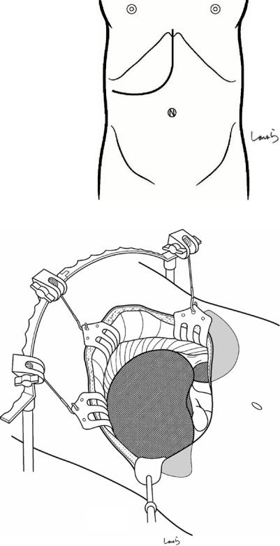
Fig. 14.1 The surgeon stands on the right side of the patient and makes a J-shaped incision in the upper abdomen. An incision curved toward the umbilicus provides a better view of the operative field in the portal region compared with an incision along the right costal arch
Fig. 14.2 A Kent retractor is applied to spread the wound in three directions. If necessary, we can use an Octopus retractor to pull the right edge of the wound laterally
Octopus retractor
14 Right Hemihepatectomy
Fig. 14.3 Adhesions between the gallbladder or underside of the liver and the transverse colon are dissected with electrocautery
Fig. 14.4 The transition line from the retroperitoneum covering the anterior surface of the kidney to the liver capsule (hepatorenal ligament) is divided with electrocautery (arrow). It is advisable to have the first assistant insert curved dissection forceps under the ligament to guide the dissection. When the
underside of the liver is
fully mobilized, a surgical Hepatorenal lig. laparotomy sponge is
placed over the colon and the anterior aspect of the stomach
329
IVC

330 |
14 Right Hemihepatectomy |
|
|
a
 Ligamentum teres
b
Falciform lig.
R coronary lig. 
Fig. 14.5 The next step is to mobilize the right lobe. The ligamentum teres is ligated with a 1-0 silk suture and then divided (a). The suture thread on the liver side is kept long enough to be pulled later and grasped with Pean forceps. The falciform ligament is then divided along its attachment to the
liver (b). The falciform ligament consists of two layers of peritoneum, which are fused into a single membrane at a certain distance from the round ligament. This ligament divides into a V-shape when approaching the inferior vena cava (IVC), continuing as the right and left coronary ligaments

14 Right Hemihepatectomy |
331 |
|
|
Falciform lig.
R coronary lig.
Fig. 14.6 As the dissection of the falciform ligament passes the apex of the V-shape, a small hole opens up, through which air enters, causing distention of cotton-like loose connective tissue. This loose connective tissue contains the root of the three hepatic veins. Curved dissection forceps are inserted through this hole, along the attach-
ment of the right coronary ligament to guide dissection with electrocautery (arrow). Do not open the forceps too wide but insert while trying to scoop the thin peritoneum only because the right hepatic vein may be attached to the right coronary ligament
Mid. hepatic v.
R hepatic v. 
Fig. 14.7 The connective tissue surrounding the right and middle hepatic veins is roughly dissected with Metzenbaum scissors or dissectors. At this point, the
approximate locations of the entrance of the veins into the liver parenchyma and the bifurcation of the veins should be determined

332 |
14 Right Hemihepatectomy |
|
|
a
 R coronary lig.
 Hepatorenal lig.
R triangular lig.
L triangular lig.
b |
Bare area |
 L coronary lig.
Fig. 14.8 The right coronary ligament ( ) and the subsequent right triangular ligament ( ) are divided along their attachment to the liver (a). In this operative angle, it is advisable to have the first assistant insert dissection forceps to guide dissection with electrocautery, although, again, the forceps should not be opened too wide so as to avoid damaging the phrenic vessels. Once the dissection is connected to the dissection
line of the hepatorenal ligament ( ) as we saw in Fig. 14.4, then two of the three sides of the bare area of the right lobe have been dissected (b). The falciform ligament forms sides and , so the hepatorenal ligament is part of it. The apical ends of the two sides are anchored to the diaphragm by the right triangular ligament ( ), which is not as easy to distinguish as the left triangular ligament
14 Right Hemihepatectomy |
333 |
|
|
Fig. 14.9 The “plane” of the bare area is detached from the surrounding structures. The plane of this triangular area is in contact with the diaphragm, the upper pole of the right kidney, and the right adrenal gland
Diaphragm
 R adrenal gland
Superior pole of R kidney
Cotton glove
Fig. 14.10 When the first assistant lifts the right lobe to the left (toward them), the accompanying diaphragm is also lifted. A cotton glove should be worn on the left hand for ease of grasping and to avoid slippage. When the surgeon applies tension by pulling back the diaphragm with forceps held in the left hand, the liver capsule is spontaneously detached from the parenchyma along with thin loose thread-like connective tissue. This dissection procedure needs only slight assistance with electrocautery
held in the right hand. In the presence of liver cirrhosis, the liver capsule may be tightly adherent due to inflammation and any attempt to detach the capsule forcibly by applying tension might injure the phrenic vessels (right inferior phrenic artery and vein), causing considerable bleeding. So, we must be sure that the dissection layer is not separated from the liver capsule. In the cranial part, we must not be careless enough to damage the right hepatic vein

334 |
14 Right Hemihepatectomy |
|
|
Fig. 14.11 After the diaphragm falls away, the right adrenal gland can be seen being pulled up by the liver. The organ can be identified by its unique ocher color. In cases of cirrhosis, because the adrenal gland may be embedded in the liver parenchyma, we should take particular care identifying the boundary when detaching the organ from the liver. It may even be safer to cut into the liver parenchyma to detach the adrenal gland from the liver
R triangular lig.
R inf. pherenic a. & v.
 Bare area
R adrenal gland
Sup. pole of R kidney
14 Right Hemihepatectomy |
335 |
|
|
Inf. vena cava
 R inf. hepatic v.
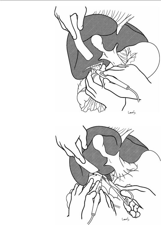
Fig. 14.12 While the first assistant holds up the right lobe cranially (not to the left), the surgeon continues detaching the adrenal gland this time from this angle of view. When the adrenal gland completely falls away, the wall of the IVC is exposed. If there is any damage to the adrenal gland, we can use 3-0 Vicryl sutures to achieve hemostasis, although considerable bleeding may still occur. During this procedure, we might encounter a quite thick short hepatic vein (the right inferior hepatic vein) as
it drains into the IVC. This vein should be either ligated and divided or should be clamped followed by division and closure with a 5-0 Prolene suture. Unknowingly cutting this vein may result in difficult-to-control bleeding. The right lobe is now mobilized. When a large tumor is present, it is advisable to first perform vascular dissection of the portal region to slightly reduce the volume of the right lobe before mobilizing it
336 |
14 Right Hemihepatectomy |
|
|
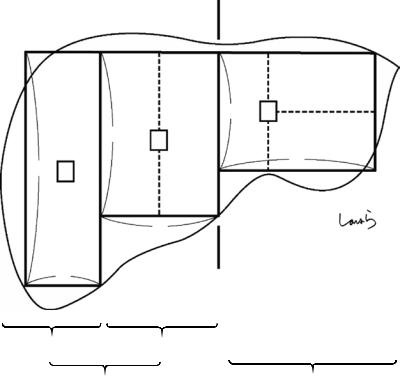
Rex-Cantlie line
3 1
4 1
4
6 1
3
2
Post. segment |
Ant. segment |
Right lobe |
Left lobe |
Fig. 14.13 Vascular anatomy of the liver: The liver is divided into the left and right lobes by the Rex-Cantlie line, and the right lobe is further divided into the anterior and posterior segments. Although the three parts of the liver are of almost similar volume, the liver has an asymmetric shape where the vertical width tapers to the left and the horizontal width of each part tapers to the right. In the
figure, each rectangle represents a different segment of the liver and all rectangles have the same area, and the right posterior segment is considerably elongated vertically compared with the left lobe. This is why in posterior segmentectomy, we might find that the discolored area after dissection of the Glissonean pedicle is smaller (thinner) than we expected
14 Right Hemihepatectomy |
|
|
337 |
|
|
|
|
Main portal arch |
|
Transverse portion (TP) |
|
P8 |
P8 |
P4b |
P2 |
P7 |
|
|
Umbilical portion |
|
A |
|
|
|
|
(UP) |
|
|
|
|
|
P |
|
|
|
P7 |
|
|
P3 |
|
|
|
|
|
|
P4a |
P3 |
P6 |
|
|
|
|
|
|
|
P5 |
P5 |
|
|
|
|
|
|
Dorsal br. |
Ventral br. |
|
|
P6 |
|
|
|
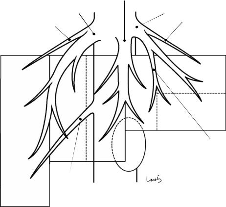
Fig. 14.14 The portal vein has been drawn onto the schematic diagram from Fig. 14.13. We should take note of several points
The right portal vein splits into the anterior (A) and posterior (P) segmental branches, with the diameter also split equally. In a Couinaud diagram of the liver, the anterior segmental branch further splits into the upper (P8) and lower (P5) branches [17]. However, the anterior segmental branch is more likely to divide into the ventral and dorsal branches. This seems natural in view of the horizontally elongated shape of the anterior segment. Each of the two branches further gives off the upper and lower branches. So, when this pattern is fitted to the Couinaud subsegment classification, the area supplied by the upper branches of the ventral and dorsal branches can be defined as S8 and the area supplied by the lower branches as S5. Actually, the Japanese guidelines for managing primary liver cancer also define S8 as the area cranial to the main bifurcation of the anterior segmental Glissonean pedicle and S5 as the area caudal to it, which is based on mapping from the liver surface than on the portal branching pattern
The posterior segmental branch, after diverging from the anterior segmental branch, travels craniodorsally forming an arch (the main portal arch). Again, it is rather unusual that this branch splits into P6 and P7, as shown in a Couinaud diagram. Instead, the posterior segmental branch usually gives off several P6 branches before giving off P7 branches. This pattern, where the main branch trav-
els downward and then ascends while giving off branches, may be advantageous in supplying blood to the entire area of the vertically elongated posterior segment. The Japanese guidelines define the area caudal to the main bifurcation of the posterior segmental Glissonean pedicle as S6 and the area cranial to the said portion as S7, which is again a segmental classification when viewed from the liver surface
The left portal vein runs transversely and, after giving off the P2 branch laterally, makes an almost right-angle turn to become the umbilical portal vein (UP). From the end of the UP, P3 arises laterally and P4 arises medially. There is usually one P2 branch and often two P3 branches. It is also common for additional small branches to arise directly from the UP between P2 and P3. P4 immediately divides into P4a coursing toward the periphery and P4b coursing proximally, although these branches often arise separately from the UP, as shown. The UP, as described in Chap. 1 on the anatomy of the stomach and surrounding structures, is an intermediate portion of the main blood supply route from the placenta to the IVC during fetal life. After birth, the umbilical vein connecting the umbilicus and the UP becomes the round ligament of the liver, while the ductus venosus (duct of Arantius) connecting the UP and the IVC becomes the ligamentum venosum, both of which are obliterated vascular remnants through which no blood flows
338 |
14 Right Hemihepatectomy |
|
|
|
|
|
Mid. hepatic v. |
|
R hepatic v. |
L hepatic v. |
|
Superficial v. |
Superficial v. |
|
(R sup. hepatic v.) |
||
(L sup. hepatic v.) |
||
|
|
S4b |
S8 |
|
|
S4a |
S5 |
Umbilical fissure v. |
|
(L medial v.) |
|
Gallbladder |
R inf. hepatic v.
S6
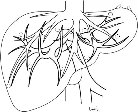
Fig. 14.15 Now the hepatic veins are drawn onto the figure. Of the three main hepatic veins (i.e., the right, middle, and left hepatic veins), the middle and left ones often form a common trunk. If we define the hepatic veins as those located along the boundaries of the three segments with an equal volume, we can regard the left hepatic vein as a branch of the middle hepatic vein. However, the left hepatic vein is essential for efficient venous return from the tip of the horizontally elongated left lobe, so we should regard it as an independent main hepatic vein
As surgeons who will be doing hepatectomies, we need a little more detailed anatomical knowledge. Each main hepatic vein appears like the leaf of Gleichenia japonica, an evergreen fern, and it receives venous return from the areas on both sides, as shown. Also, several adjunctive veins, including the superficial veins at both ends, are present as if filling the gaps between these main hepatic veins. Of these, the umbilical fissure vein, located between the left and middle hepatic veins, ascends along the UP and, while receiving venous return from S3 and S4, converges with the left hepatic vein. This is one of the veins that we should pay attention to during lateral segmentectomy
The middle hepatic vein splits into two parts at its terminal; the right vein receives venous return from the ventral part of S5 and the left vein from S4a. In the middle part, the middle hepatic vein receives two branches from
the right and left sides, with the right branch receiving venous return from S8 and the left one from S4b. The vein finally converges with the left hepatic vein and drains into the IVC. This is the basic branching pattern of the middle hepatic vein. Between the split veins at the terminal is the hepatic bed of the gallbladder. The liver parenchyma intervenes between the vein and the gallbladder but is only about 5 mm thick. We should keep this vein in mind when excising a severely inflamed gallbladder
During right hemihepatectomy, veins draining to the right wall of the middle hepatic vein are encountered on the transection plane. Liver dissection proceeds along the Rex-Cantlie line from the periphery while dissecting branches from S5. Once the right wall of the main trunk is exposed, intraoperative ultrasonography is done to identify at least one or two large branches from S8 that will probably be encountered before reaching the root of the middle hepatic vein. This helps to avoid unnecessary bleeding
If we think about the efficiency of venous return, the caudal part of the vertically elongated posterior segment (right segment), or S6, has the disadvantage that it is quite far from the root of the right hepatic vein. For this reason, a large branch directly draining into the IVC, which is located nearby, can often be identified as the right inferior hepatic vein. In right hemihepatectomy, this vein is often encountered during the procedure to detach the adrenal gland and must be dissected with care
14 Right Hemihepatectomy |
339 |
|
|
|
|
2 |
|
8 |
4b |
7 |
8 |
3 |
|
4a
5 |
5 |
|
6
Fig. 14.16 Finally, we superimpose the portal and hepatic veins. The numbers correspond to those of subsegments defined by Couinaud. The hepatic vein branches correspond to each portal branch
340 |
14 Right Hemihepatectomy |
|
|
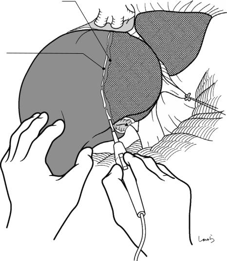
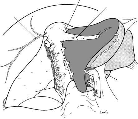
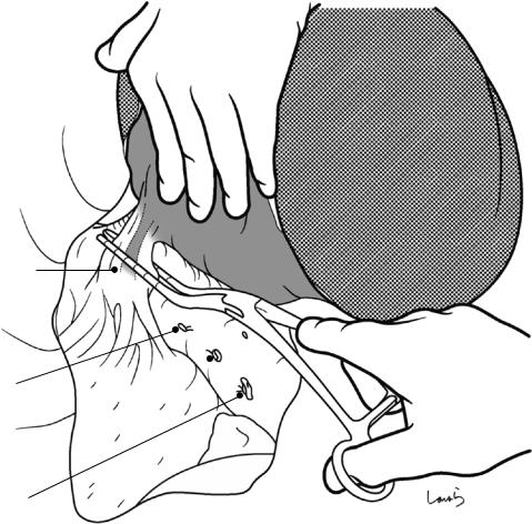
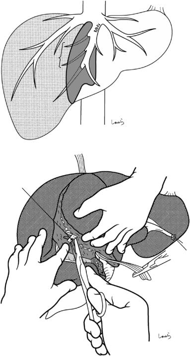
Fig. 14.17 We move on in the operation to manipulation of the hilar region. The portal region can be dealt with either by en bloc transection of the Glissonean pedicle or by individual isolation, ligation, and division of the hepatic artery, portal vein, and bile duct. Because the main objective of this book is to illustrate the local anatomy, we will focus on the latter technique hereon in. The first assistant scoops the underside of S4 cranially with an intestinal spatula while pulling up the round ligament to secure the operative field. At the same time, the surgeon places the
left index and middle fingers on both sides of the hepatoduodenal ligament and pulls the pyloric region and duodenum caudally to spread the ligament wide. The procedure begins with cholecystectomy. A peritoneal incision on the hepatoduodenal ligament should be made along a large circle (arrows) for ease of the subsequent manipulation of the right Glissonean vessels. (In routine cholecystectomy, a sharp-angled V-shaped incision with the cystic duct as the apex should be made)
14 Right Hemihepatectomy |
341 |
|
|
Cystic a.
R hepatic a.
Mid. hepatic a.
Common hepatic duct
Cystic duct
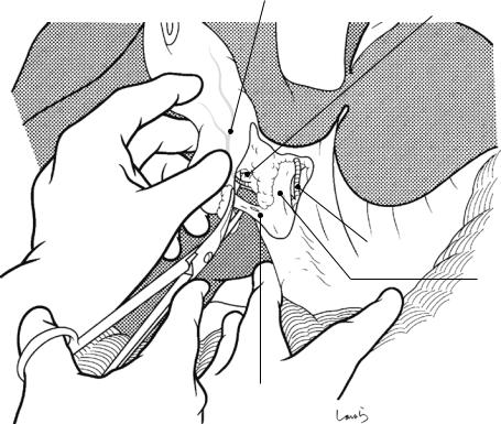
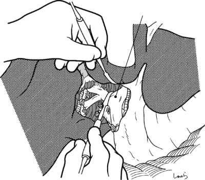
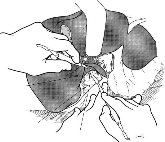
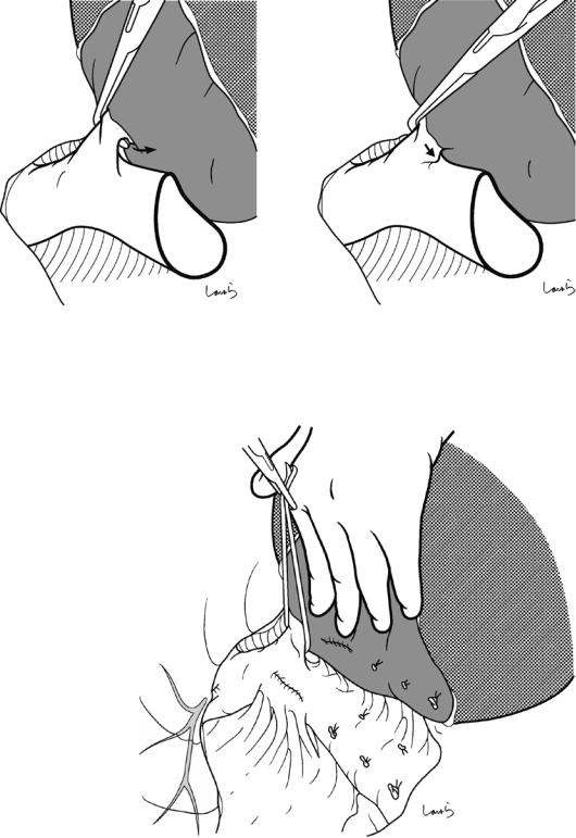
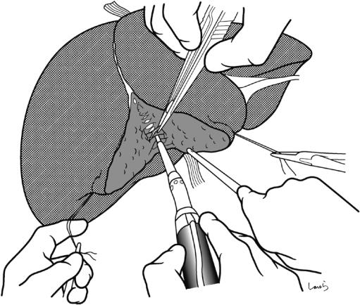
Fig. 14.18 The fat tissue in the triangle of Calot is scraped up toward the gallbladder with Cooper scissors to expose the cystic duct and the cystic artery embedded there. The duct and artery are ligated and divided separately. At this point, the wall of the right hepatic artery from which the cystic artery branches is usually partially exposed and seen to be pulsatile. The gallbladder is then
detached from the hepatic bed and excised. Here again, it is advisable to excise the gallbladder with connective tissue remaining on the gallbladder side to make sure that no excess tissue remains on the hepatic bed side, unlike in routine cholecystectomy, so that subsequent vascular dissection and parenchymal dissection are quicker
342 |
14 Right Hemihepatectomy |
|
|
Liver bed
Mesocyst
Cystic duct (ligated)
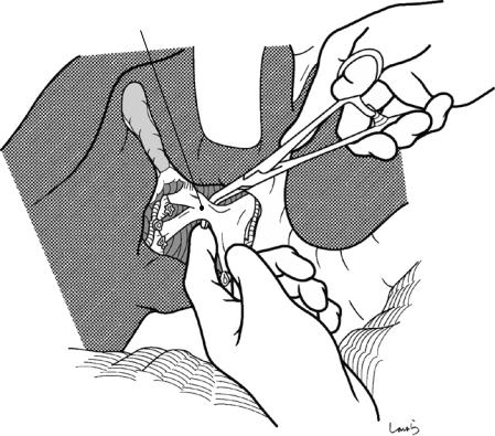
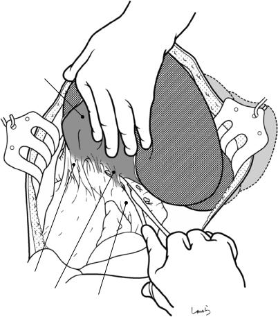
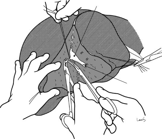
Fig. 14.19 Residual fat tissue may be present in the triangle of Calot after cholecystectomy. This is the “mesocyst” intervening between the gallbladder and the
extrahepatic Glissonean pedicle. This should be scooped with dissecting forceps and divided so that the right hepatic artery can be easily identified
14 Right Hemihepatectomy |
343 |
|
|
Ant. segmental br. of hepatic duct
5 |
R hepatic a. |
|
|
|
8 |
Mid. hepatic a.
5
6
L hepatic a.
8
6
7 |
7 |
Cystic a. |
|
Post. segmental br. of hepatic duct
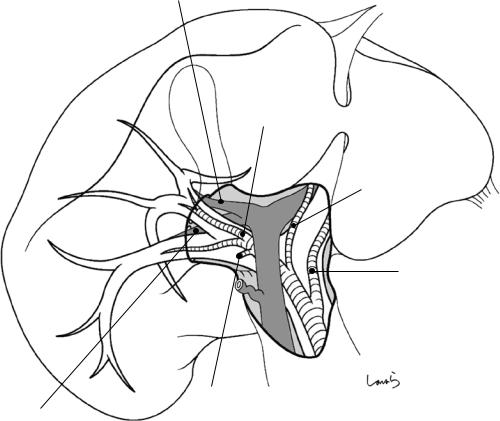
Fig. 14.20 Note that when viewed from the operative angle for portal manipulation, the branching pattern of the Glissonean vessels appears differently from that viewed from the front in Fig. 14.16. More specifically, the S5 branches in the anteroinferior segment run upward, while the S8 branches in the anterosuperior segment run downward behind the posterior segmental branches. The main portal arch of the posterior segmental branch (S7 posterosuperior segmental branch) curves downward, while the
S6 posteroinferior segmental branch courses upward. The right hepatic artery courses almost along the portal vein on its ventral side. The right hepatic duct usually courses cranial to the portal vein, so it can appear gradually to be hidden behind the portal vein when viewed from this angle. In rare cases though, the posterior segmental branch of the hepatic duct crosses in front of the anterior segmental branch of the portal vein or branches from the left hepatic duct, so we should keep these variations in mind
344 |
14 Right Hemihepatectomy |
|
|
R portal v. |
Common hepatic duct |
 Cystic duct (ligated)
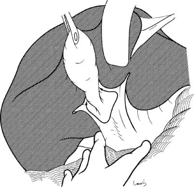
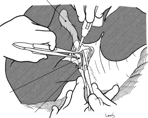
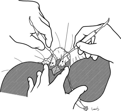
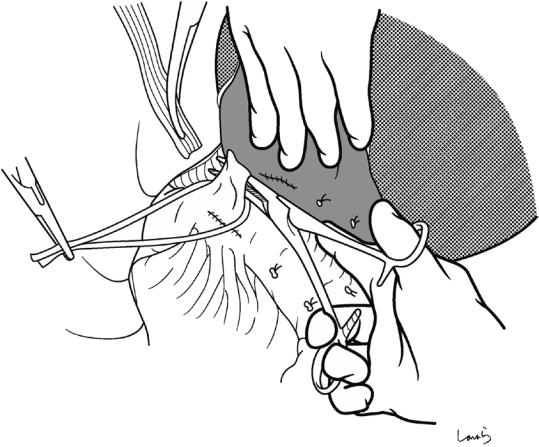
Fig. 14.21 The connective tissue around the right hepatic artery is scooped with right-angled dissecting forceps and dissected with electrocautery to expose the entire circum-
ference of the arterial wall. The artery is scooped with the forceps and then ligated and divided
14 Right Hemihepatectomy |
345 |
|
|
Paracaval portion of caudate lobe
R hepatic a. (cut)
* Caudate br. of R portal v.
R hepatic a. (root)
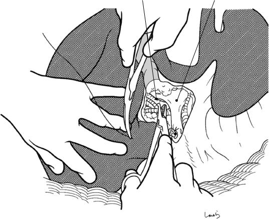
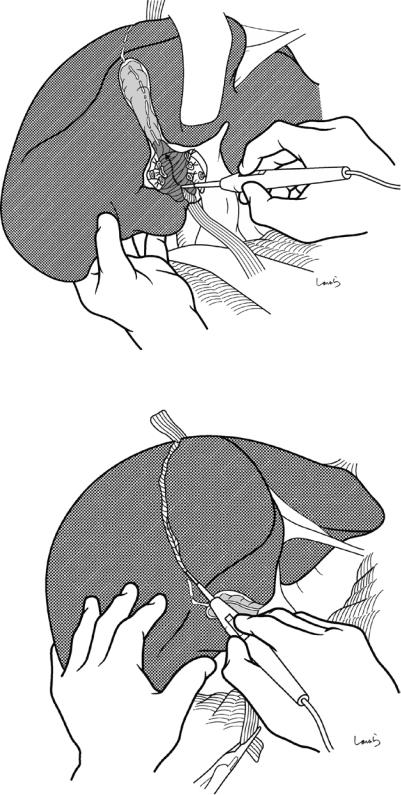
Fig. 14.22 When the right hepatic artery has been divided, we can see the dark blue-colored anterior wall of the right portal vein below. Using two dissectors is effective for isolating the portal vein. First, the concave surface of the bifurcation of the right and left portal veins is accessed from the upper border. Then, the right portal vein is lifted from the parenchyma of the caudate lobe. By
slightly lifting the portal vein with the dissector held by the left hand to secure the operative field and then pushing the liver parenchyma with the dissector held by the right hand, we can easily—but gradually—detach the portal vein from the parenchyma. Look out for a small branch (asterisk) arising from the dorsal side of the right portal vein and draining into the paracaval portion of the caudate lobe
346 |
14 Right Hemihepatectomy |
|
|
R portal v.
Caudate process
Caudate br. of R portal v.
Fig. 14.23 Then, the same procedure is performed from the lower border of the liver. One to two small branches entering the caudate process are identified and then ligated and divided. Although ligation of the hepatic side of the portal vein may be performed at this level, there is a risk that the ligation suture could fall off during other proce-
dures due to the large diameter of the portal vein. Dissecting the anterior and posterior segmental branches separately is not so timeor labor-consuming, so we should do this, especially when it might be difficult to secure an adequate margin for closing the stump of the right portal vein
14 Right Hemihepatectomy |
347 |
|
|
Ant. branch
Caudate br. (ligated)
Post. branch
Fig. 14.24 The bifurcation of the anterior and posterior segmental branches is exposed using two dissectors and is then detached from the liver parenchyma
348 |
14 Right Hemihepatectomy |
|
|
Fig. 14.25 Each branch is scooped with right-angled dissecting forceps guided by the left index finger and divided after double-ligation (one by piercing suture). If we find that the tip of the forceps does not penetrate the connective tissue smoothly, do not push it forcibly and instead
just try again after making a path with a dissector. There is still a long way until we complete the operation, so the stump on the resection side should also be closed by reliable piercing ligation to make sure that the ligation suture will not come off during other procedures
14 Right Hemihepatectomy |
349 |
|
|
Ant. br. of PV (root)
Ant. br. of PV (ligated)
R hepatic a. (ligated)
|
R hepatic a. (root) |
|
Post. br. of PV |
|
PV |
(ligated) |
|
|
|
(L border) |
|
Caudate process
IVC
Post. br. of PV (root)
Fig. 14.26 Once the right portal vein has been transected, the parenchyma of the caudate lobe can be seen below. The parenchyma is thinnest in this concave area, with the caudate process on the right and the lobule of
Spiegel on the left, as well as the Glissonean vessels of the right portal region on the upper side and the IVC on the bottom side. So, it is advisable to start parenchymal dissection from this area (see Fig. 14.41)
350 |
14 Right Hemihepatectomy |
|
|
Rex-Cantlie line
Transection line of liver parenchyma
Fig. 14.27 Because the right hepatic artery and right portal vein have been transected, the right lobe is discolored to a dark red, bordered by the Rex-Cantlie line. An
imaginary transection line is set 5 mm to the right of the line and marked with electrocautery
14 Right Hemihepatectomy |
351 |
|
|
Bifurcation of R and L hepatic ducts
Fig. 14.28 Finally, the hepatic duct located deepest behind the right Glissonean pedicle has to be dissected. Compared with the extrahepatic bile duct, whose wall is smooth and can be easily isolated, the hepatic duct is much more fibrous and difficult to isolate. The bifurcation of the right and left hepatic ducts is covered by a thick Glissonean capsular membrane of the hilar plate and is
firmly adherent to and embedded within the S4 parenchyma. Accessing this part is the first step toward identifying the hepatic duct. The connective tissue is dissected extensively so that even the liver parenchyma can be dissected. The dissection also proceeds from the lower border
352 |
14 Right Hemihepatectomy |
|
|
R hepatic duct
Fig. 14.29 Even after a considerable amount of dissection, we will not get the forceps to pass through the connective tissue around the hepatic duct. Do not be tempted to push because you could end up with bile leakage postoperatively. Instead explore other options to pass the forceps through smoothly. Once you have managed this, you will feel so relieved that you will find you can now relax
your shoulders. The right hepatic duct is ligated and divided to complete portal manipulation. If isolating and identifying the hepatic duct is difficult, it is safer to proceed with parenchymal dissection first and then return to hepatic duct isolation after the dissection has reached the hilar plate
14 Right Hemihepatectomy |
353 |
|
|
Planes to which right and left lobes attach
= dissection plane along Rex-Cantlie line
R hepatic v. Mid. hepatic v.
A
*
L
R
B
IVC
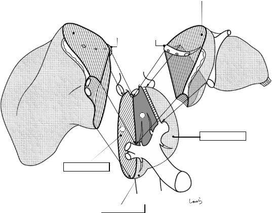
Fig. 14.30 Before moving on to the next step of dissecting the short hepatic vein, we would like to review the anatomy of the caudate lobe. The caudate lobe is usually divided into three parts: lobule of Spiegel, paracaval portion, and caudate process. The caudate lobe is the only hepatic lobe in contact with the IVC and which provides planes to which the right and left lobes attach. The plane cut obliquely and laterally from a line connecting the root of the middle hepatic vein (A) and the bifurcation of the anterior and pos-
terior segmental branches from the Glissonean pedicle (B), plane , is the right border of the lobe and is where the right lobe attaches. The trapezoidal area bounded by the duct of Arantius (asterisk) and the horizontal part of the Glissonean pedicle, plane , is the plane to which the left lobe attaches. The Glissonean vessels enter the caudate lobe immediately after splitting into the right and left primary branches, and the venous blood directly returns into the IVC through the short hepatic veins
354 |
14 Right Hemihepatectomy |
|
|
L hepatic v.
Mid. hepatic v.
R inf. phrenic v.
R hepatic v. |
|
|
|
* |
|
Liver bed |
|||
|
|
|
|
||||||
|
|
|
|
|
|||||
Ligamentum |
|
|
|
|
|
|
|||
|
|
|
|
|
|
|
|
||
venae cavae |
|
|
|
|
* |
|
|
||
|
|
|
|
|
|
|
|||
|
|
|
|
|
* |
|
|
||
|
|
|
Membranous |
|
|
|
|
Lobule of Spiegel |
|
|
|
|
connective tissue |
|
|
|
|||
|
|
|
|
|
|
|
|
||
|
|
R inf. hepatic v. |
|
|
|
|
|
||
|
|
|
|
|
|
|
IVC |
||
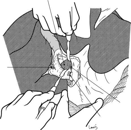
Fig. 14.31 We move next to dissection of the short hepatic veins. These veins can be divided into two groups: those draining into the anterior aspect of the IVC (asterisk) and those draining into the right lateral aspect of the IVC. The latter are embedded in the membranous connective tissue that anchors the liver to the right border of the IVC. First, the former are dissected via a caudal approach and then the latter via a right lateral approach.
When the liver is transected along the Rex-Cantlie line, the resulting cross section is in the shape of a wedge with a short base. Surprisingly, when we look at a resected specimen of the liver, the base (i.e., the attachment of the liver to the IVC) is actually only about 5 cm long. Dissecting the short hepatic veins is the most thrilling part of doing a right hemihepatectomy and can be referred to as “the 5-cm-of-fear step”
14 Right Hemihepatectomy |
355 |
|
|
Caudate process
R inf. hepatic v. (ligated)
Inf. vena cava
Fig. 14.32 The short hepatic veins draining into the anterior aspect of the IVC are dissected first. After repositioning the liver to allow for portal manipulation, the interface between the caudate process and the anterior aspect of the IVC is divided with two dissectors. The connective tissue in this area is loose and contains two to three veins measuring 2–3 mm in diameter. These vessels are sequentially
scooped with right-angled dissecting forceps and ligated and divided. After this 5-cm-of-fear step, the root of the middle hepatic vein can be identified. This liver position provides a good view of the operative field and allows the first assistant and other assistants to clearly see what the surgeon is doing. Completely dissecting these veins will make it easier to perform the subsequent procedure
356 |
14 Right Hemihepatectomy |
|
|
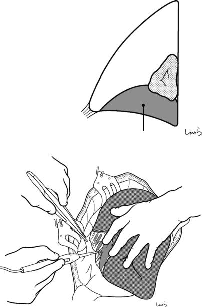
Bare area
Lig. venae cavae
Short hepatic v.
Inf. vena cava
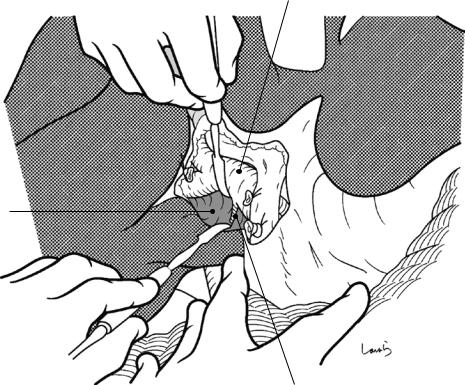
Fig. 14.33 The short hepatic veins draining into the right lateral aspect of the IVC are dissected next. The first assistant displaces the right lobe to the left (toward them). This stretches membranous connective tissue between the IVC and the right lobe. This connective tissue contains a thick short hepatic vein. Curved dissecting forceps are inserted behind the connective tissue along the liver parenchyma, and the vein is scooped together with the connective tissue and ligated and divided. This membranous connective tis-
sue thickens slightly as it approaches the bifurcation of the hepatic veins (see Fig. 14.31), turns around the dorsal aspect of the IVC, and attaches to lobule of Spiegel. This connective tissue is referred to as the ligamentum venae cavae, and it anchors the IVC to the inferior vena caval fossa. At this point, the dissection proceeds immediately before reaching the ligament. Now, all three sides of the bare area of the right lobe (see Fig. 14.8b) have been dissected
14 Right Hemihepatectomy |
357 |
|
|
a |
|
Lobe hooked at |
b |
|
|
||
|
|
edge of wound |
Space formed in |
|
|
|
|
|
|
|
cavity |
|
|
|
Short hepatic v. |
|
|
|
fully stretched |
|
R adrenal gland |
|
|
|
|
Ao |
IVC |
|
R kidney |
|
|
|
|
|
Bad displacement |
|
Good displacement |
|
|
|
Fig. 14.34 The success of this procedure depends on whether the surgeon and the first assistant can share a good view of the operative field. If the first assistant simply pulls the right lobe, the liver then obscures the operative field and the short hepatic vein is not fully stretched (a). If the right lobe is pulled after the left lobe has been firmly pushed into the space formed in the left abdominal
cavity (arrow), the posterior aspect of the liver rises upright, providing a good operative field of view (b). Also, the IVC is deformed by the displaced right lobe into a “comma” shape and has become so thin that it may be ruptured by the dissecting forceps unless inserted along the liver parenchyma
358 |
14 Right Hemihepatectomy |
|
|
Mid. hepatic v.
R hepatic v.
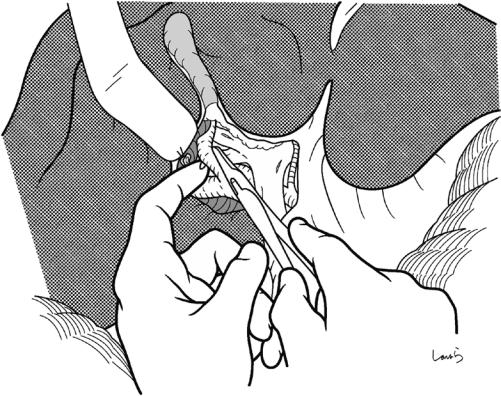
Fig. 14.35 Dissection of the right hepatic vein: After repositioning the liver to its original position, the medial border of the root of the right hepatic vein is exposed using dissectors. The dissection should be performed as distally as possible so that any possible rupture can be
repaired easily. However, because the dome-like bulging of the liver parenchyma interferes with the procedure, we should advance the dissection as if digging into the parenchyma. A small area of the parenchyma around the bifurcation can be dissected with electrocautery as shown
14 Right Hemihepatectomy |
359 |
|
|
Lig. venae cavae
Short hepatic v.  (ligated)
R inf. hepatic v. (ligated)
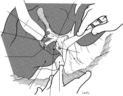
Fig. 14.36 The right lobe is again displaced to the left. The ligamentum venae cavae is then divided lateral to the right hepatic vein. This ligament might also contain a short hepatic vein and, if encountered, it should be clamped with a hemostat inserted along the liver, divided, and suture-closed with a 5-0 Prolene suture. The IVC is
slightly thinned around this ligament and deformed by displacement of the right lobe. The division of the ligament allows the right lobe to be lifted further, exposing the lateral border of the right hepatic vein. At times, the parenchyma may extend into the ligament

360 |
14 Right Hemihepatectomy |
|
|
a
R hepatic v.
Lig. venae cavae (sutured)
b
Fig. 14.37 Right-angled dissecting forceps are inserted via a recess formed between the anterior surface of the IVC and the root of the right hepatic vein and then advanced carefully along the liver through the connective
tissue (a). If the tip of the forceps does not pass through the connective tissue smoothly, do not push it but try again after making a path with a dissector. Inserting the forceps from the caudal side can achieve penetration smoothly (b)
14 Right Hemihepatectomy |
361 |
|
|
a |
b |
|
Safe |
|
Unsafe |
|
|
|
Fig. 14.38 The root of the right hepatic vein has been considerably thinned by the comma-like deformation of the IVC and its constriction with the right hepatic vein at the apex. Because of this, the vein can easily be ruptured
Fig. 14.39 Vascular tape is passed around the encircled right hepatic vein and grasped with mosquito forceps. The right hepatic vein may be divided at this point if it has a sufficiently long neck, although parenchymal dissection is usually started without dividing the vein. Sometimes, even encircling the vein is difficult. In such cases, we can start parenchymal dissection without encircling the vein
by the tip of the right-angled dissecting forceps if facing outward (b). So, we should insert the forceps along the liver (a)
362 |
14 Right Hemihepatectomy |
|
|
Fig. 14.40 As a guide for determining direction during parenchymal dissection, a Penrose drain is passed under the right hepatic vein, pulled out between the IVC and the caudate process, and grasped with Pean forceps. Before
starting the dissection, intraoperative echography is repeated to determine the course of the hepatic veins crossing the Rex-Cantlie line
14 Right Hemihepatectomy |
363 |
|
|
Fig. 14.41 The parenchymal dissection should be started from the interface between the caudate process and lobule of Spiegel because this is where the parenchyma is the thinnest. The dissection can be done in one stroke using the preplaced Penrose drain as a pillow, although efforts should be made to minimize the area dissected, at least by avoiding swerving to
the left
Fig. 14.42 Parenchymal dissection is performed along the line previously marked with electrocautery. The first incision can be made with electrocautery because there are no major cord-like structures up to a depth of about 5 mm
364 |
14 Right Hemihepatectomy |
|
|
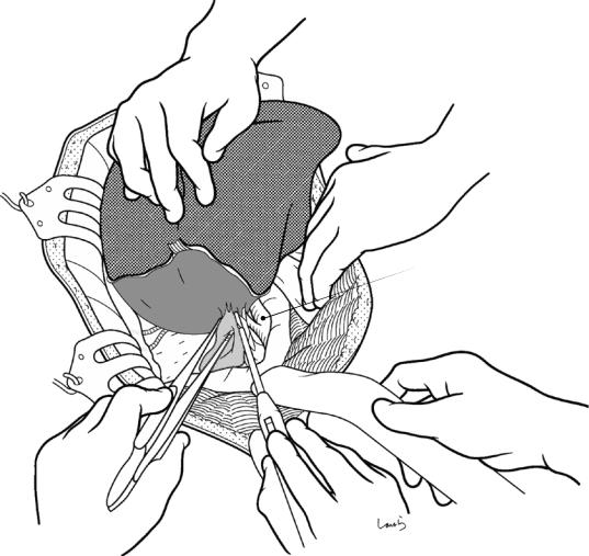
First assistant’s right hand
(saline-coupled bipolar electrocautery device)
First assistant’s left hand
Second assistant’s right hand
|
Surgeon’s right hand |
Surgeon’s left hand |
holding a CUSA |
|
Fig. 14.43 Various devices and techniques can be used for parenchymal dissection, but here we look at using a Cavitron Ultrasonic Surgical Aspirator (CUSA) and a saline-coupled bipolar electrocautery device. Traction sutures are placed at the edge of the planned transection line. The first assistant holds the suture thread on the rem-
nant side, while the surgeon holds the suture thread on the resection side to adjust the size of the dissection plane. The surgeon is in charge of manipulating the CUSA, the first assistant is in charge of saline-coupled bipolar electrocautery, and the second assistant is in charge of the suction tube
14 Right Hemihepatectomy |
365 |
|
|
a
V8 |
* |
V4b |
|
||
|
|
|
|
|
V4a |
V5 |
|
|
b
V5
 Dissected caudate process
Fig. 14.44 Most of the vessels appearing on the dissection plane along the Rex-Cantlie line are veins. Dissecting the thin parenchyma at the liver floor 5–6 cm reaches the point where the middle hepatic vein (MHV) splits into the right and left branches (asterisk in a). Of these branches, the branch that receives venous return from S5 is scooped
with right-angled dissecting forceps (b) and is ligated and divided. The dissection then advances proximally along the right side of the MHV while dissecting small branches along the venous wall. At least one or two more large branches from S8 are encountered before reaching the root of the MHV
366 |
14 Right Hemihepatectomy |
|
|
Mid. hepatic v.
V5 (ligated)
Clip applier
Fig. 14.45 Venous branches ≥2–3 mm in diameter should be scooped with right-angled dissecting forceps, ligated on the remnant side, clipped on the resection side, and divided with Metzenbaum scissors. It is advisable to leave the clipping clamp unlocked until the dissection is complete. Thin veins can be cauterized and divided with
bipolar electrocautery. The thin threadand cord-like structures appearing on the dissection plane are mostly bile ducts. These should also be carefully cauterized and divided with bipolar electrocautery. Be careful here to avoid causing bile leakage postoperatively
14 Right Hemihepatectomy |
|
367 |
|
|
|
|
|
Mid. hepatic v. |
V8 (ligated) |
V5 (ligated) |
|
R hepatic v. |
|
|
|
|
|
|
|
|
|
|
|
Fig. 14.46 After advancing the parenchymal dissection proximally and approaching the bifurcation of the right and middle hepatic veins, the parenchyma in that area is carefully divided by fragmentation and aspiration with the
CUSA in the direction toward the vascular tape placed on the right hepatic vein. The right hepatic vein is clamped with a hemostat and the specimen is excised. The stump is then closed with a 5-0 Prolene suture
368 |
14 Right Hemihepatectomy |
|
|
Dissection plane of paracaval portion of caudate lobe
Sutured R hepatic v.
Dissection plane of caudate process
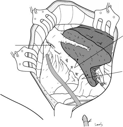
Fig. 14.47 After excising the specimen, the abdominal cavity is washed and hemostasis of the dissection plane is achieved using a 4-0 PDS suture or by electrocautery for fine bleeding points. We should confirm the absence of bile leakage by applying new gauze on the dissection
plane. After washing the abdominal cavity again, an 8-mm duple drain is placed in the right subphrenic region and the operation is completed by closing the abdominal wall, suturing in three layers