

Инновационные процессы в исследовательской и образовательной деятел
..pdfМинистерство образования и науки Российской Федерации Федеральное государственное бюджетное образовательное учреждение высшего профессионального образования
«Пермский национальный исследовательский политехнический университет»
ИННОВАЦИОННЫЕ ПРОЦЕССЫ В ИССЛЕДОВАТЕЛЬСКОЙ И ОБРАЗОВАТЕЛЬНОЙ
ДЕЯТЕЛЬНОСТИ
INNOVATIONS IN RESEARCH
AND EDUCATION ACTIVITIES
Материалы
IV Международной научной конференции (г. Пермь, 21 апреля 2015 г.)
Издательство Пермского национального исследовательского
политехнического университета
2015
1
ББК 72.5в4 + 74.480.25 И66
В сборник включены тезисы докладов молодых ученых, аспирантов, соискателей и магистрантов, представленных на международной конференции, посвященной инновационным решениям актуальных вопросов современной науки и техники.
Редакционная коллегия:
И.А. Авхачева – канд. пед. наук, доц. каф. иностранных языков, лингвистики и перевода ПНИПУ Е.Л. Кавардакова – доц. каф. иностранных языков, лингвистики и перевода ПНИПУ
Т.А. Горева – канд. пед. наук, доц. каф. иностранных языков, лингвистики и перевода ПНИПУ Н.В. Чудинова – доц. каф. иностранных языков, лингвистики и перевода ПНИПУ
В.В. Звягина – канд. пед. наук, доц. каф. иностранных языков, лингвистики и перевода ПНИПУ С.Г. Улитина – канд. пед. наук, доц. каф. иностранных языков, лингвистики и перевода ПНИПУ
Л.П. Раскопина – канд. пед. наук, доц. каф. иностранных языков, лингвистики и перевода ПНИПУ А.Ю. Наугольных – канд. пед. наук, доц. каф. иностранных языков, лингвистики и перевода ПНИПУ
ISBN 978-5-398-01522-5 |
© ПНИПУ, 2015 |
2
D.A. Kuznetsov
Die nationale polytechnische Forschungsuniversität Perm
CHARAKTERISTIKA DER SCHWEISSRAUCH-FESTKOMPONENTE
In this paper the results of an empirical research of welding fumes solid ingredient are described. Certain types, forms, constitutions and degrees of dispersion are observed.
Key words: welding fumes, solid ingredient of welding fumes, clusters, agglomerates, occupational diseases of welder.
Die bei schweißtechnischen Prozessen entstehenden Scheißrauche haben eine gesundheitsschädigende Wirkung auf den Schweißer.
Der Schweißrauch hat zwei Komponenten. Das sind eine gasförmige
Komponente (GK) und eine Festkomponente (FK). Die durchgeführte praktische Untersuchung bezieht sich auf die Festkomponente, die aus ultrafeinen Partikeln (manchmal weniger als 1 Mikrometer) zusammensetzt ist. Diese werden vom Schweißer bis in die Lungen eingeatmet, wobei auch eine Berufslungenkrankheit entstehen kann [1].
Die schadhafte Wirkung der FK kann durch ihre Morphologie, Dispersität und chemische Zusammensetzung bedingt werden, die ihrerseits mit dem Elektrodentyp verbunden sind.
In diesem Zusammenhang wurde eine FK untersucht, die sich auf das
Kohlenstoffklebeband, das an einem Schweißerschutzhelm befestigt worden war, ablagerte, indem bei den Lichtbogenhandschweißen verschiedene Elektrodentype verbraucht werden.
Das Schweißen wurde auf einer Stahlplatte (Marke 20, Stärke 10 mm, Elektrodendicke 3 mm, Schweißstrom 90 A) unter Verwendung eines Schweißgleichrichters VD-306 durchgeführt. Dabei werden verschiedene Elektroden verbraucht: Kb-Elektroden (Kobe Steel LB 52U), Titandioxydelektroden (ESAB OK 53.70, OK 46.00), Zelluloseelektroden (Kjellberg Finsterwalde Prima Blau) und saure Elektroden (MR-3M) [2].
Es ließen sich Partikel unterschiedlicher Formen feststellen: kugelförmige
Partikel, Agglomerate und Clustern. Die Hauptbestandteile der FK sind kugelförmige Partikel, die in zwei Typen aufgeteilt werden: Partikel mit faserartiger und mit glatter Oberfläche. Beide Typen der kugelförmigen Partikel sind Eisenoxide, die als Begleitelemente Titan und Aluminium enthalten. Die faserartigen Partikel beinhalten auch Silizium und Kalium [3].
Bei der chemischen Analyse der Partikel zeigte sich, dass sie in der Regel komplexe mineralartige Zusammensetzungen darstellen und keine Eisenoxide
3
sind, wie man früher meinte. Die Agglomerate sind Mehrkomponentensysteme, die aus Fe2O3, Fe3(SO4) und K (AlSi3O8) mit Titan-Beimischungen bestehen.
Eine Untersuchung der Partikelfeinheit ließ erkennen, dass die Partikelgrößen unterschiedlich sind, wobei diese Größe vom Elektrodentyp abhängig ist. So können Agglomerate je nach Elektrodentyp eine Größe von 5 bis
45 μт und Cluster eine Größe bis zu 22 μт und eine Breite bis zu 8 μт haben. Die kugelförmigen Partikel haben je nach ihrer Oberfläche eine Größe von 18 bis zu
40 μт. Bei den unter dem Gesichtspunkt des verbrauchten Elektrodentyps durchgeführten Untersuchungen der Partikelfeinheit wurde festgestellt, dass die Belastung durch die feinsten Partikel am höchsten ist.
Für eine Bewertung der gesundheitsschädigenden Wirkung der Schweiß- rauch-Festkomponente beim Verbrauch von Schweißwerkstoffen sind die wichtigsten Charakteristika der ultrafeinen Partikel zu berücksichtigen. Deswegen ist die Untersuchung der physikalisch-mechanischen, chemischen und morphologischen Eigenschaften der FK bezogen auf unterschiedliche Schweißstoffe für den Arbeitsschutz beim Schweißen von großer Bedeutung [1].
Literaturverzeichnis
1.Кузнецов Д.А., Наумов С.В. Характеристика твердой составляющей сварочных аэрозолей различных видов электродных покрытий // Сварка и диагностика-2012: сб. докл. науч. техн. конф. / ЗАО «Уральские выставки». – Екатеринбург, 2012. – С. 110–114.
2.Кузнецов Д.А., Игнатов М.Н., Игнатова А.М. Лабораторные методы определения параметров твердой составляющей сварочных аэрозолей [Электронное издание] // Сварка и диагностика: сб. докл. междунар. форума. – Екатеринбург: Изд-во УрФУ, 2014. – С. 80–85.
3.Кузнецов Д.А. Исследование физико-химических характеристик твердой составляющей сварочных аэрозолей: материалы работ победителей и лауреатов всерос. конкурса науч.-исслед. работ студ. и аспир. в обл. техн. наук. – СПб: Изд-во СПбГТУ, 2012. – С. 205–207.
4
N.V. Kozlov, G.M. Tolkachev
Perm National Research Polytechnic University
ELIMINATION OF MUD AND CEMENT SLURRY LOSS IN DEEP WELL DRILLING AT THE VERKHNEKAMSKOE POTASSIUM AND MAGNESIUM DEPOSIT
The problem of disastrous lost circulation in drilling wells at the territory of Verkhnekamskoe potassium and magnesium deposit is being treated. Importance of this problem is shown and the concept of its solving is defined.
Key words: mud and cement slurry loss, conductor well drilling, well casing, cementing, lost circulation zone.
Nowadays one of the important ways of increasing the efficiency and quality of well building is by reducing the time and money spent on elimination of mud and cement slurry loss.
The significance of this problem is getting worse if other minerals are developed on the territory of well building and its further exploitation. Destruction of any well casing elements in the mining zone may lead to emergency situations [1].The Verkhnekamskoye potassium and magnesium salt deposit (VPMSD), where joint development of oil and mineral salts has been conducted for more than 40 years is a striking example of that [2].
In 2014 in the area of the "LUKoil-Perm" licensed oil deposit (Southern oil trap of Yurchukskoe field) that is co-located with the Verkhnekamskoye potassium and magnesium salts deposit, seven wells were drilled by the drilling enterprise "NSH ASIA DRILLING", four of which, when conductor drilled, got into lost-circulation zones. Elimination of these failures by the repeated placing of cement plugs was often ineffective because even in the absence of fluid loss the cement slurry did not reach the cellar. At the same time cementing at the wellhead was possible only after the casing perforation and further cementing of tubing-casing annulus through the perforations. It caused an increase in direct costs of lost circulation zones, and those associated with the damage control of unsuccessful separation when cementing. It should be noted that during the conductor cementing of the last 3 wells in the group, complications were not noticed, which was due to experience, previously obtained by opening-out of the similar zones, and timely preventing of complications by means of the cement plug placing based on Portland cement.
In 2006, to eliminate absorption in drilling post-salt deposits, gypsum compositions magnesia cementing materials (GMTM) were developed in
5
PNIPU and successfully applied on Shershnevskoye field (VPMSD). The main advantages of GMTM compared with traditional plugging materials are that the emerging cement stone has a much higher strength and an adhesive bond with salts, and its mixture with formation water has a shorter thickening time [3]. However, the use of the special plugging materials is often complicated by the variety of geological conditions.
References
1.Использование магнезиальных цементов в бурении скважин и добыче нефти / Г.М. Толкачев, Ю.А. Дулепов, А.М. Шилов, В.А. Мордвинов; Центр. правление науч.-техн. общества нефт. и газ. пром. им. И.М. Губкина. –
М., 1987. – C. 3.
2.Сборник нормативных документов, регламентирующих порядок строительства глубоких скважин при освоении нефтяных месторождений на площади залегания калийных солей Верхнекамского месторождения (Пермский край). – Пермь, 2006.
3.Пат. 2273724 Рос. Федерация. Тампонажный состав для изоляции зон поглощений при бурении скважин / Г.М. Толкачев, А.М. Шилов, А.С. Козлов, С.А. Копытова; заяв. и патентообл. ФГБОУ ВПО ПНИПУ;
опубл. 10.10.2004 г.
6
V.Y. Zverev
Perm National Research Polytechnic University
ANALYSIS OF DATA OBTAINED BY HOIST DYNAMIC MONITORING TO DETERMINE EXTRA LOADS
ON THE WIRE ROPE
In this paper, the problem of dynamic forces existing on the wire rope during mining hoist operation is described. The current system of hoist dynamic monitoring and the results of its application were presented. Analyzing of obtained data was held and conclusions about origins of dynamic forces on the wire rope were done.
Key words: mining hoist, skip, wire rope, dynamic loads, upright acceleration.
The increase in mining hoist system productivity is closely connected with the increase in lifting intensity which involves using skips with greater load capacity and at a higher speed. As one can see from previous research on hoist operation, moving shaft conveyance is accompanied by extra acceleration, and, as a result, dynamic loads on the wire rope. These loads reduce the durability of hoist system and, accordingly, increase its operational cost. If the weight of the skip increases and it moves at a higher speed, dynamic loads in the wire rope also increase [1].
The vibration of the shaft conveyance caused by dynamic loads in the wire rope is referred to as extra acceleration which occurs during each skip lifting. That is why the dynamic measurement of the skip acceleration is the best method when it comes to assessing the value and character of the loads, which occur during hoist operation [2].
This method of measurement involves installing “ARMIR” equipment on the shaft conveyance, and obtaining data from acceleration sensors during a few cycles of lifting a loaded skip and lowering an empty skip. Measurements are taken while the hoist is operated automatically. As a result of the dynamic monitoring of hoist operation, the data on skip acceleration are obtained. Then diagrams of the upright acceleration acting in a longitudinal direction to the wire rope are considered to analyze of loads applied to the rope.
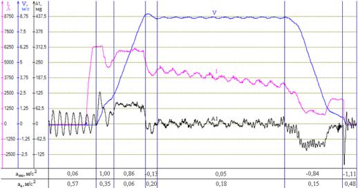
The measurements were taken at the hoist equipped with a SN-19,5 shaft skips and the “BRIDON” wire rope having a diameter 63 mm. As a result of the dynamic monitoring conducted and the data analysis, the diagrams of the shaft conveyances upright acceleration were obtained. Fig. 1 shows schematically the view of a skip move in coincidence with the information about the hoist. As a unit of measurement for skip upright acceleration 1 mg (equals 9,81·10–3 m/sec2) has been chosen, which is determined by the sensors used.
The method of analyzing a skip upright acceleration diagram has the following steps:
7
–segregation of a hoist operation periods with their characteristic vibrations;
–determining of the maximum and minimum acceleration peak values
(amax , amin );
– calculation of average parameters, which characterize the skip movement. These parameters are the average acceleration a ms and the amplitude of vibration a a . Both parameters are calculated using the following formulas:
a |
ms |
|
amax amin |
; a |
a |
|
amax amin |
. |
|
2 |
|
2 |
|
||||
|
|
|
|
|
||||
The lifting cycle under consideration was divided into 7 typical mining hoist operation periods (Figure): loading ore in a skip; starting of the hoist drum; a speedup; accelerating till the maximum speed; a reregulation of lifting speed; a uniform movement; a slowdown; stopping followed by skip vibrations.
Fig. Diagram of the skip movement during an ore lifting
When analyzing the skip movement, peak values of acceleration for each cycle of hoist operation were determined. The values of average acceleration and vibration amplitude of the skip were aligned with the acceleration diagram.
As we see in fig. 1, the maximum skip amplitude occurs when ore is being loaded, when the skip starts moving and when it stops. Certain skip operation periods are characterized by specific types of vibration. Accordingly, the factors that cause vibration are different, and should be considered separately for each period of hoist operation.
1. Loading ore is carried out when the skip is freely hanging on the wire rope. Thus, an oscillatory process occurs because of a change in conveyance weight within a short period of time. During loading skip, dynamic forces in the wire rope depend on the duration, the magnitude and the character of the pulsa-
8
tion caused by irregular flow by the loaded ore. Basically, these parameters are determined by loading cartridge structural features [3].
2.When we begin to start the driving engine, the hoist drum is still arrested and the skip does not move. It is explained by the fact that the drive of the brakes is not synchronized with the hoist engine. Such operational regime brings about an additional increase in the armature current. As a result, the jerk power at the moment of starting has a greater value. The resulting jerk is accompanied by the oscillations of the skip.
3.Skip stopping is accompanied by the hoist locking. At the same time, the current in the engine armature decreases dramatically and then terminates. Simultaneously with this, a brake is pressed against the brake drum rim. The skip, due to the power of inertia, keeps moving upwards making the rope tightening weaker and loose. Then, affected by the weight of the vessel and due to the main rope elasticity, the skip starts vibrating (or, swinging), which is typical of stopping the hoist mechanism [4].
The dynamic monitoring of the mine hoist operation and the analysis of the data obtained make it possible to determine actual loads affecting the rope. Using the result of the analysis, we can find out the reasons for skip oscillations. This information, taken into account when adjusting the skip or, in case of troubleshooting, will allow the necessary operational regime alterations, which will lead to decreasing or total eradicating the dynamic loads. This will increase the durability of the wire rope and its reliability, while reducing operation costs related to hoist.
References
1.Воробель С.В., Трифанов Г.Д. Влияние диаграммы скорости на динамические нагрузки в системе «подъемный сосуд – жесткая армировка» и деформацию рамы подъемного сосуда // Горное оборудование и электромеханика. – 2011. – № 12. – С. 16–19.
2.Ильин С.Р., Трифанов Г.Д., Воробель С.В. Повышение безопасности эксплуатации шахтных стволов путем динамического мониторинга систем «сосуд – армировка» портативными измерительными станциями // Горное оборудование и электромеханика. – 2013. – № 1. – С. 2–8.
3.Трифанов Г.Д. Повышение срока службы канатов и эффективности эксплуатации шахтных подъемных установок: автореф. дис. … д-ра техн. наук / Урал. гос. горный ун-т. – Екатеринбург, 2013.
4.Ильин С.Р., Послед Б.С. Хаотические колебания подъемных сосудов при ударном взаимодействии с проводниками жесткой армировки вертикальных стволов // Известия вузов. Горный журнал. – 2014. – № 2. –
С. 92–98.
9
S.K. Berezin, A.A. Shevtsov, S.K. Grebenkov
Perm National Research Polytechnic University
STRUCTURE AND MECHANICAL PROPERTIES OF LOW CARBON MARTENSITIC STEEL HARDENED FROM THE INTERCRITICAL TEMPERATURE RANGE
The paper deals with tempering peculiarities of low-carbon martensitic steel 15H2G2NMFB in the intercritical temperature range at 810 C ° is studied. Combinations of strength, ductility and toughness, making it possible to replace the standard quenching (980 ° C), for tempering in the intercritical temperature range are achieved.
Key words: martensite, toughness, strength, resistance to tempering, intercritical temperature range.
Introduction
Conventional carbon steels containing 0.20–0.40 % of carbon have insufficient structural strength and workability when heat-strengthened parts are manufactured. The problem of increasing the structural strength, durability and corrosion resistance are essential in mechanical engineering. Annual irretrievable loss of more than a third of the world's metal and about 90 % of breakdowns of machines is caused by insufficient wear resistance, fatigue strength and corrosion resistance [1]. The need for an integrated approach to solving these problems is obvious. Research into the structure transformation kinetics and mechanical properties of low-carbon martensitic steels (LCMS) showed their high strength, ductility and toughness. Untempered LCMS have high ductility and toughness due to the low concentration of carbon in solid solution, which is important in the processes of rolling. Today, low-carbon martensitic steels are the most promising in terms of an integrated approach, as they have a high structural strength and resistance to tempering [2], which is especially important, since most of the surface hardening processes are accompanied by prolonged exposure to elevated temperatures.
Methods of Experimenting and Research
The microstructure was studied with the digital camera Levenhuk C800 (camera resolution of 1280x1024 pixels) of the microscope “Neophot-32” under magnification from 100 to 1000-fold. In order to reveal the microstructure, the surface of the metallographic section was etched with 4% nitric acid. KCV toughness was determined according to state standard 9454-78 on the pendulum impact testing machine IO 5003-0,3 on samples (Sample Size: 10x10 mm) with a V-notch. Resistance to tempering of LCMS containing strong carbide forming elements was investigated (table).
10