

ASME B31.1-2010
---`,,`,,`,`,,`-`-`,,```````,,```,`,`,,,,`,`,`,`--
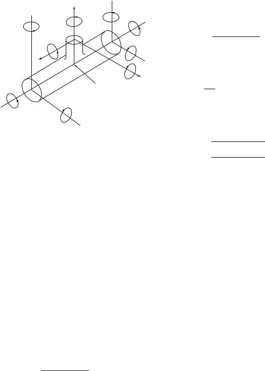
Fig. 104.8.4 Cross Section Resultant
Moment Loading
y
My2
My3
My1
Mz2
Mz3
Mx2
z
Mx3
x
Junction of legs
Mz1
Mx1
operating load range and eq. (1A) are typically used, in.-lb (mm-N) [see paras. 102.3.2(B), 104.8.4, and 119.7].
104.8.4Moments and Section Modulus
(A)For eqs. (15), (16), and (17), the resultant moments for straight through components, curved pipe, or welding elbows may be calculated as follows:
Mj p (Mxj2 + Myj2 + Mzj2)1/2
te p effective branch wall thickness, in. (mm)
plesser of tnh or itnb in eq. (17), or lesser of tnh or 0.75itnb, where 0.75i ≥ 1.0, in eqs. (15) and (16)
For the reduced outlet branch connections covered by Fig. D-1,
MA, MB,
MC p Mx32 + My32 + Mz32
and
Z p r′m2Tb
If L1 in Fig. D-1, sketches (a), (b), and (c) equals or exceeds 0.5 riTb, then r′m can be taken as the radius to the center of Tb when calculating the section modulus and the stress intensification factor. For such a case, the transition between branch pipe and nozzle must be evaluated separately from the branch connection.
For the main run outlets,
MA, MB,
MC p Mx12 + My12 + Mz12 p Mx22 + My22 + Mz22
and
Z p section modulus of pipe, in.3 (mm3)
PART 3
SELECTION AND LIMITATIONS OF PIPING
COMPONENTS
where
jp A, B, or C as defined in paras. 104.8.1, 104.8.2, and 104.8.3
Z p section modulus of piping, in.3 (mm3)
(B)For full outlet branch connections, calculate the resultant moment of each leg separately in accordance with (A) above. Use Z, section modulus, in eqs. (15), (16), and (17) as applicable to branch or run pipe. Moments are taken at the junction point of the legs. See Fig. 104.8.4.
(C)For reduced outlets, calculate the resultant moment of each leg separately in accordance with (A) above. Moments are to be taken at the junction point of the legs, unless the designer can demonstrate the validity of a less conservative method. See Fig. 104.8.4. For the reduced outlet branch, except for branch connections covered by Fig. D-1,
MA, MB,
MC p Mx32 + My32 + Mz32
and
Z p rb2te (effective section modulus)
rb p branch mean cross-sectional radius, in. (mm)
33
105 PIPE
105.1 General
Pipe conforming to the standards and specifications listed in Appendix A shall be used within the range of temperatures for which allowable stresses are given within the limitations specified herein.
105.2Metallic Pipe
105.2.1Ferrous Pipe
(A)Furnace butt welded steel pipe shall not be used for flammable, combustible, or toxic fluids.
(B)Ductile iron pipe may be used for design pressures within the ratings established by the standards and specifications listed in Tables 126.1 and A-5 and Notes thereto, and the limitations herein and in para. 124.6. Ductile iron pipe shall not be used for flammable, combustible, or toxic fluids. Temperature limits for the use of ductile iron pipe are often determined by the type of elastomeric gasket used in the pipe joints, or the lining material used on the internal surface of the pipe. It is the reponsibility of the Designer to determine whether these components are suitable for use in the particular application being considered. See para. 106.1(E).
Copyright ASME International
Provided by IHS under license with ASME
No reproduction or networking permitted without license from IHS
ASME B31.1-2010
105.2.2Nonferrous Pipe
(A)Copper and brass pipe for water and steam service may be used for design pressures up to 250 psi (1 750 kPa) and for design temperatures to 406°F (208°C).
(B)Copper and brass pipe for air may be used in accordance with the allowable stresses given in the Allowable Stress Tables.
(C)Copper tubing may be used for dead-end instrument service with the limitations stated in para. 122.3.2(D).
(D)Copper, copper alloy, or aluminum alloy pipe or tube may be used under the conditions stated in para. 124.7. Copper, copper alloy, or aluminum pipe or tube shall not be used for flammable, combustible, or toxic fluids except as permitted in paras. 122.7 and 122.8.
105.3Nonmetallic Pipe
(A)Plastic pipe may be used for water and nonflammable liquids where experience or tests have demonstrated that the plastic pipe is suitable for the service conditions, and the pressure and temperature conditions are within the manufacturer’s recommendations. Until such time as mandatory rules are established for these materials, pressure shall be limited to 150 psi (1 000 kPa) and temperature to 140°F (60°C) for water service. Pressure and temperature limits for other services shall be based on the hazards involved, but in no application shall they exceed 150 psi (1 000 kPa) and 140°F (60°C). For nonmandatory rules for nonmetallic piping, see Appendix III of this Code.
(B)Reinforced thermosetting resin pipe may be used, in addition to the services listed in para. 105.3(A), in buried flammable and combustible liquid service subject to the limitations described in para. 122.7.3(F).
(C)Reinforced concrete pipe may be used in accordance with the specifications listed in Table 126.1 for water service up to 150°F (65°C).
(D)A flexible nonmetallic pipe or tube assembly may be used in applications where
(D.1) satisfactory service experience exists
(D.2) the pressure and temperature conditions are within the manufacturer’s recommendations
(D.3) the conditions described in paras. 104.7, 124.7, and 124.9 are met
(E)Polyethylene pipe may be used, in addition to the services listed in para. 105.3(A), in buried flammable and combustible liquid and gas service subject to the limitations described in paras. 122.7.2(D) and 122.8.1(B.4).
(F)Metallic piping lined with nonmetals may be used for fluids that would corrode or be contaminated by unprotected metal. See para. 122.9 and Appendix III.
106 FITTINGS, BENDS, AND INTERSECTIONS
106.1 Fittings
(A) Threaded, flanged, grooved and shouldered socket-welding, buttwelding, compression, push-on,
mechanical gland, and solder-joint fittings made in accordance with the applicable standards in Table 126.1 may be used in power piping systems within the material, size, pressure, and temperature limitations of those standards, and within any further limitations specified in this Code. Material for fittings in flammable, combustible, or toxic fluid systems shall in addition conform to the requirements of paras. 122.7 and 122.8.
(B)Fittings not covered by the Standards listed in Table 126.1 may be used if they conform to para. 104.7.
(C)Cast buttwelding steel fittings not covered by the dimensional standards listed in Table 126.1 may be used up to the manufacturer’s pressure and temperature ratings, provided they are radiographed in accordance with the method of ASTM E 94 and meet the acceptance requirements of ASTM E 446, E 186, and E 280 as applicable for the thickness being radiographed.
(D)Fabricated ends for grooved and shouldered type joints are acceptable, provided they are attached by full penetration welds, double fillet welds, or by threading. Fabricated ends attached by single fillet welds are not acceptable.
(E)Elastomeric gasket bell end fittings complying with applicable standards listed in Table 126.1 may be used for water service. Temperature limits for gray and ductile iron fittings using ANSI/AWWA C111/A21.11 joints are 65°C (150°F) for push-on joints and 49°C (120°F) for mechanical joints, based on standard water service gasket and lining materials. Fittings of this type using alternative materials, as allowed by AWWA C111, may be used for nonflammable, nontoxic service to 100°C (212°F), where suitability for the fluid and operating conditions has been established by test or experience. Temperature limits for bell and spigot fittings in nonmetallic pipe shall be per para. 105.3.
106.2 Bends and Intersections
Bends and extruded branch connections may be used when designed in accordance with the provisions of paras. 104.2 and 104.3, respectively. Miters may be used within the limitations of para. 104.3.3.
106.3 Pipe Couplings and Unions
(A)Cast iron and malleable iron pipe couplings shall be limited in application as referenced in paras. 124.4 and 124.5, respectively.
(B)Straight thread couplings shall not be used.
(C)Class 3000 steel pipe unions constructed in accordance with the MSS standard SP-83 may be used, provided the system design conditions are within the standard’s listed pressure–temperature ratings.
106.4Flexible Metal Hose Assembly
(A)Flexible metal hose assemblies may be used to provide flexibility in a piping system, to isolate or control vibration, or to compensate for misalignment. The
34
--`,,```````,,```,`,`,,,,`,`,`,`-`-`,,`,,`,`,,`---
Copyright ASME International
Provided by IHS under license with ASME
No reproduction or networking permitted without license from IHS
ASME B31.1-2010
design conditions shall be in accordance with para. 101 and within the limitations of the assembly as recommended by the manufacturer. The basis for their application shall include the following service conditions: thermal cycling, bend radius, cycle life, and the possibility of corrosion and erosion. Installation shall be limited to a single-plane bend, free from any torsion effects during service conditions and nonoperating periods. Type of end-connector components shall be consistent with the requirements of this Code.
(B)A flexible metal hose assembly, consisting of one continuous length of seamless or butt welded tube with helical or annular corrugations, is not limited as to application in piping systems that are within the scope of this Code, provided that the conditions described in
(A)above are met. For application subject to internal pressure the flexible element shall be contained within one or more separate layers of braided metal permanently attached at both coupling ends by welding or brazing. For application in toxic fluid systems, it is recommended that the designer also review the standards published by the relevant fluid industry for any additional safety and materials requirements that may be necessary.
(C)A flexible metal hose assembly consisting of wound interlocking metal strips may be applied to atmospheric vent systems only and shall not be used in systems that convey high temperature, flammable, toxic, or searching-type fluids. Where applicable, as determined by the designer and within the limitations described in para. 122.6 and those imposed by the manufacturer, this type of hose assembly may be used at pressure relieving devices.
107 VALVES
107.1 General
(10)
(10) --`,,```````,,```,`,`,,,,`,`,`,` -`- `,,`,,`,`,,`---
(A)Valves complying with the standards and specifications listed in Table 126.1 shall be used within the specified pressure–temperature ratings. Unless otherwise required in the individual standards and specifications listed in Table 126.1, such steel valves shall be pressure tested in accordance with MSS SP-61.
(B)Valves not complying with (A) above shall be of a design, or equal to the design, that the manufacturer recommends for the service as stipulated in para. 102.2.2. Such valves shall be pressure tested in accordance with MSS SP-61.
(C)Some valves are capable of sealing simultaneously against a pressure differential between an internal cavity of the valve and the adjacent pipe in both directions. Where liquid is entrapped in such a valve and is subsequently heated, a dangerous rise in pressure can result. Where this condition is possible, the Owner shall provide means in design, installation, and/or operation to ensure that the pressure in the valve shall not exceed
35
the rated pressure for the attained temperature. A relief device used solely for the overpressure protection from such entrapped fluid and conforming to (A) or (B) above need not comply with the requirements of para. 107.8. Any penetration of the pressure retaining wall of the valve shall meet the requirements of this Code.
(D)Only valves designed such that the valve stem is retained from blowout by an assembly that functions independently of the stem seal retainer shall be used.
(E)Materials used for pressure retention for valves in flammable, combustible, or toxic fluid systems shall in addition conform to the requirements of paras. 122.7 and 122.8.
(F)When selecting diaphragm valves in accordance with MSS standard SP-88, the designer shall specify the proper category pressure–temperature rating for the system design conditions, and should consider the expected in-service and shelf lives of the diaphragm material.
(G)Pressure regulating valves may have pressure ratings in accordance with ANSI/FCI Standard 79-1. Regulators having two static pressure ratings, i.e., inlet vs. outlet, shall be installed with adequate overpressure protection devices to prevent excessive downstream pressure resulting from any system failure. Refer to paras. 122.5 and 122.14.
107.2 Marking |
(10) |
Each valve shall bear the manufacturer’s name or trademark and reference symbol to indicate the service conditions for which the manufacturer guarantees the valve. The marking shall be in accordance with ASME B16.5 and B16.34. MSS SP-25 may also be used for guidance.
107.3 Ends
Valves may be used with flanged, threaded, butt welding, socket welding, or other ends in accordance with applicable standards as specified in para. 107.1(A).
107.4 Stem Threads
Where threaded stem valves are used, stem threads may be internal or external with reference to the valve bonnet. Outside screw and yoke design shall be used for valves NPS 3 and larger for pressures above 600 psi (4 135 kPa). This requirement is not applicable to quar- ter-turn valves that comply with all other provisions of this Code.
107.5 Bonnet Joints
Bonnet joints may be of flanged, welded, pressure seal, union type, or other design, except that screwed bonnet connections in which the seal depends on a steam tight threaded joint shall not be permitted as source valves in steam service at pressures above 250 psi (1 750 kPa).
Copyright ASME International
Provided by IHS under license with ASME
No reproduction or networking permitted without license from IHS
ASME B31.1-2010
107.6 Bypasses
Sizes of bypasses shall be in accordance with MSS SP-45 as a minimum standard. Pipe for bypasses shall be at least schedule 80 seamless, and of a material of the same nominal chemical composition and physical properties as that used for the main line. Bypasses may be integral or attached.
107.8Safety, Safety Relief, and Relief Valves
107.8.1General. Safety, safety relief, and relief valves shall conform to the requirements specified in this Code for flanges, valves, and fittings for the pressures and temperatures to which they may be subjected.
107.8.2Safety, Safety Relief, and Relief Valves on Boiler External Piping. Safety, safety relief, and relief valves on boiler external piping shall be in accordance with para. 122.1.7(D.1) of this Code.
107.8.3Safety, Safety Relief, and Relief Valves on Nonboiler External Piping. Safety, safety relief, and relief valves on nonboiler external piping (except for reheat safety valves) shall be in accordance with the requirements of the ASME Boiler and Pressure Vessel Code, Section VIII, Division 1, UG-126 through UG-133. For valves with set pressures 15 psig [100 kPa (gage)] and lower, an ASME Code Stamp and capacity certification are not required. Reheat safety valves shall be in accordance with the requirements of the ASME Boiler and Pressure Vessel Code, Section I, PG-67 through PG-73.
107.8.4Nonmandatory Appendix. For nonmandatory rules for the design of safety valve installations, see Appendix II of this Code.
108PIPE FLANGES, BLANKS, FLANGE FACINGS, GASKETS, AND BOLTING
108.1 Flanges
Flanges shall conform to the design requirements of para. 104.5.1 or to the standards listed in Table 126.1. They may be integral or shall be attached to pipe by threading, welding, brazing, or other means within the applicable standards specified in Table 126.1.
108.2 Blanks
Blanks shall conform to the design requirements of para. 104.5.3.
108.3 Flange Facings
Flange facings shall be in accordance with the applicable standards listed in Tables 112 and 126.1. When bolting Class 150 standard steel flanges to flat face cast iron flanges, the steel flange shall be furnished with a flat face. Steel flanges of Class 300 raised face standard may be bolted to Class 250 raised face cast iron.
108.4 Gaskets
Gaskets shall be made of materials that are not injuriously affected by the fluid or by temperature. They shall be in accordance with Table 112.
108.5U.S. Customary Bolting
108.5.1General
(A)Bolts, bolt studs, nuts, and washers shall comply with applicable standards and specifications listed in Tables 112 and 126.1. Bolts and bolt studs shall extend completely through the nuts.
(B)Washers, when used under nuts, shall be of forged or rolled material with steel washers being used under steel nuts and bronze washers under bronze nuts.
(C)Nuts shall be provided in accordance with the requirements of the specification for the bolts and bolt studs.
(D)Alloy steel bolt studs shall be either threaded full length or provided with reduced shanks of a diameter not less than that at the root of the threads. They shall have ASME heavy hexagonal nuts. Headed alloy bolts shall not be used with other than steel or stainless steel flanges.
(E)All alloy steel bolt studs and carbon steel bolts or bolt studs and accompanying nuts shall be threaded in accordance with ASME B1.1 Class 2A for external threads and Class 2B for internal threads. Threads shall
be the coarse-thread series except that alloy steel bolting 11⁄8 in. and larger in diameter shall be the 8-pitch-thread series.
(F)Carbon steel headed bolts shall have square, hex, or heavy hex heads (ASME B18.2.1) and shall be used
with hex or heavy hex nuts (ASME B18.2.2). For bolt sizes smaller than 3⁄4 in., square or heavy hex heads and heavy hex nuts are recommended. For bolt sizes larger than 11⁄2 in., bolt studs with a hex or heavy hex nut on each end are recommended. For cast iron or bronze flanges using 3⁄4 in. and larger carbon steel headed bolts, square nuts may be used.
108.5.2For the various combinations of flange materials, the selection of bolting materials and related rules concerning flange faces and gaskets shall be in accordance with para. 108 and Table 112.
108.5.3Bolting requirements for components not covered by para. 108.5.2 shall be in accordance with para. 102.2.2.
108.6Metric Bolting
108.6.1General. The use of metric bolts, bolt studs, nuts, and washers shall conform to the general requirements of para. 108.5, but the following are allowed:
(A)Threads shall be in accordance with ASME B1.13M, M profile, with tolerance Class 6g for external threads and Class 6H for internal threads.
--`,,```````,,```,`,`,,,,`,`,`,`-`-`,,`,,`,`,,`--- |
36 |
Copyright ASME International
Provided by IHS under license with ASME
No reproduction or networking permitted without license from IHS