

ASME B31.1-2010
or dye penetrant inspection of the first layer, of each 1⁄4 in. (6 mm) thickness of deposited weld metal, and of the finished weld surface. Magnetic particle or dye penetrant testing of the finished weld surface shall be done after postweld heat treatment.
(C) For cast iron and nonferrous materials, no increase of the casting quality factor is allowed except when special methods of examination, prescribed by the material specification, are followed. If such increase is specifically permitted by the material specification, a factor not exceeding 1.0 may be applied.
104.1.2 Straight Pipe Under Internal Pressure — Seamless, Longitudinal Welded, or Spiral Welded and Operating Below the Creep Range
(A) Minimum Wall Thickness. The minimum thickness of pipe wall required for design pressures and for temperatures not exceeding those for the various materials listed in the Allowable Stress Tables, including allowances for mechanical strength, shall not be less than that determined by eq. (7) or (8), as follows:
tm p |
PDo |
|
+ A |
(7)3 |
|
2(SE + Py) |
|||||
|
|
|
|||
102.4.7 Weld Strength Reduction Factors. At elevated temperatures, seam welds on longitudinal-welded or spiral-welded pipe can have lower creep strength than the base material. This reduction is a factor in determining the minimum wall thickness for longitudi- nal-welded or spiral-welded pipe (i.e., not seamless), whether fabricated in accordance with a material specification or fabricated in accordance with the rules of this Code. The weld strength reduction factor, W, is given in Table 102.4.7. The designer is responsible to assess application of weld strength reduction factor requirements for welds other than longitudinal and spiral, as applicable (e.g., circumferential welds).
PART 2
PRESSURE DESIGN OF PIPING COMPONENTS
103CRITERIA FOR PRESSURE DESIGN OF PIPING COMPONENTS
The design of piping components shall consider the effects of pressure and temperature, in accordance with paras. 104.1 through 104.7, including the consideration of allowances permitted by paras. 102.2.4 and 102.4. In addition, the mechanical strength of the piping system shall be determined adequate in accordance with para. 104.8 under other applicable loadings, including but not limited to those loadings defined in para. 101.
104 PRESSURE DESIGN OF COMPONENTS
104.1Straight Pipe
104.1.1Straight Pipe Under Internal Pressure.
Straight pipe under internal pressure shall have a minimum wall thickness calculated per para. 104.1.2 if the pipe is of seamless construction or is designed for sustained operation below the creep range. Straight pipe under internal pressure shall have a minimum wall thickness calculated per para. 104.1.4 if the pipe is of longitudinal-welded or spiral-welded construction designed for sustained operation within the creep range. (See para. 123.4 for definition of the creep range.)
tm p |
Pd + 2SEA + 2yPA |
(8)3 |
|
2(SE + Py − P) |
|||
|
|
Design pressure shall not exceed
P p |
2SE(tm − A) |
|
(9)3 |
|||
Do |
− 2y(tm − A) |
|||||
|
|
|
||||
P p |
|
2SE(tm − A) |
(10)3 |
|||
d − 2y(tm − A) + 2tm |
||||||
|
|
|||||
where the nomenclature used above is:
(A.1) tm p minimum required wall thickness, in. (mm)
(A.1.1) If pipe is ordered by its nominal wall thickness, the manufacturing tolerance on wall thickness must be taken into account. After the minimum pipe wall thickness tm is determined by eq. (7) or (8), this minimum thickness shall be increased by an amount sufficient to provide the manufacturing tolerance allowed in the applicable pipe specification or required by the process. The next heavier commercial wall thickness shall then be selected from thickness schedules such as contained in ASME B36.10M or from manufacturers’ schedules for other than standard thickness.
(A.1.2) To compensate for thinning in bends, refer to para. 102.4.5.
(A.1.3) For cast piping components, refer to para. 102.4.6.
(A.1.4) Where ends are subject to forming or machining for jointing, the wall thickness of the pipe, tube, or component after such forming or machining shall not be less than tm minus the amount provided for removal by para. 104.1.2 (A.6.1).
3 SF shall be used in place of SE where casting quality factors are intended. See definition of SE. Units of P and SE must be identical. Appendix A values must be converted to kPa when the design pressure is in kPa.
--`,,```````,,```,`,`,,,,`,`,`,`-`-`,,`,,`,`,,`--- |
19 |
Copyright ASME International
Provided by IHS under license with ASME
No reproduction or networking permitted without license from IHS

ASME B31.1-2010
Table 102.4.7 Weld Strength Reduction Factors to Be Applied When Calculating the Minimum Wall Thickness or Allowable Design Pressure of Components Fabricated With a Longitudinal Seam Fusion Weld
|
|
|
|
Weld Strength Reduction Factor for Temperature, °F (°C) [Notes (1)–(6)] |
|
|||||||
|
700 |
750 |
800 |
850 |
900 |
950 |
1,000 |
1,050 |
1,100 |
1,150 |
1,200 |
|
Steel Group |
(371) |
(399) |
(427) |
(454) |
(482) |
(510) |
(538) |
(566) |
(593) |
(621) |
(649) |
|
|
|
|
|
|
|
|
|
|
|
|
|
|
Carbon (Norm.) [Notes (7), (8)] |
1.00 |
0.95 |
0.91 |
NP |
NP |
NP |
NP |
NP |
NP |
NP |
NP |
|
Carbon (Sub Crit) [Notes (8), (9)] |
1.00 |
0.95 |
0.91 |
NP |
NP |
NP |
NP |
NP |
NP |
NP |
NP |
|
CrMo [Notes (8), (10), (11)] |
. . . |
. . . |
1.00 |
0.95 |
0.91 |
0.86 |
0.82 |
0.77 |
0.73 |
0.68 |
0.64 |
|
CSEF (N+T) [Notes (8), (12), (13)] |
. . . |
. . . |
. . . |
. . . |
. . . |
1.00 |
0.95 |
0.91 |
0.86 |
0.82 |
0.77 |
|
CSEF (Sub Crit) [Notes (8), (9)] |
. . . |
. . . |
. . . |
. . . |
1.00 |
0.73 |
0.68 |
0.64 |
0.59 |
0.55 |
0.50 |
|
Austenitic stainless (incl. 800H & |
. . . |
. . . |
. . . |
. . . |
. . . |
1.00 |
0.95 |
0.91 |
0.86 |
0.82 |
0.77 |
|
800HT) [Notes (14), (15)] |
|
|
|
|
|
|
|
|
|
|
|
|
Autogenously welded austenitic |
. . . |
. . . |
. . . |
. . . |
. . . |
1.00 |
1.00 |
1.00 |
1.00 |
1.00 |
1.00 |
|
stainless [Note (16)] |
|
|
|
|
|
|
|
|
|
|
|
|
|
|
|
|
|
|
|
|
|
|
|
|
|
NOTES:
(1)NP p not permitted.
(2)Longitudinal welds in pipe for materials not covered in this Table operating in the creep regime are not permitted. For the purposes of this Table, the start of the creep range is the highest temperature where the nonitalicized stress values end in Mandatory Appendix A for the base material involved.
(3)All weld filler metal shall be a minimum of 0.05% C for CrMo and CSEF materials, and 0.04% C for austenitic stainless in this Table.
(4)Materials designed for temperatures below the creep range [see Note (2)] may be used without consideration of the WSRF or the rules of this Table. All other Code rules apply.
(5)Longitudinal seam welds in CrMo and CSEF materials shall be subjected to, and pass, a 100% volumetric examination (RT or UT). For materials other than CrMo and CSEF, see para. 123.4(B).
(6)At temperatures below those where WSRFs are tabulated, a value of 1.0 shall be used for the factor W where required by the rules of this Section. However, the additional rules of this Table and Notes do not apply.
(7)Norm. p normalizing postweld heat treatment (PWHT) is required.
(8)Basicity index of SAW flux ≥ 1.0.
(9)Sub Crit p subcritical PWHT is required. No exemptions from PWHT are permitted. The PWHT time and temperature shall meet the requirements of Table 132; the alternate PWHT requirements of Table 132.1 are not permitted.
(10)The CrMo steels include 1⁄2Cr–1⁄2Mo, 1Cr–1⁄2Mo, 11⁄4Cr–1⁄2Mo–Si, 21⁄4Cr–1Mo, 3Cr–1Mo, and 5Cr–1⁄2Mo. Longitudinal welds shall either be normalized, normalized and tempered, or subjected to proper subcritical PWHT for the alloy.
(11)Longitudinal seam fusion welded construction is not permitted for C–1⁄2Mo steel for operation in the creep range [see Notes (2) and (4)].
(12)The CSEF (creep strength enhanced ferritic) steels include Grades 91, 92, 911, 122, and 23.
(13)N+T p normalizing + tempering PWHT.
(14)WSRFs have been assigned for austenitic stainless (including 800H and 800HT) longitudinally welded pipe up to 1,500°F as follows:
Temperature, °F |
|
Temperature, °C |
Weld Strength Reduction Factor |
|
1,250 |
|
677 |
|
0.73 |
1,300 |
704 |
0.68 |
||
1,350 |
732 |
0.64 |
||
1,400 |
760 |
0.59 |
||
1,450 |
788 |
0.55 |
||
1,500 |
816 |
0.5 |
||
(15)Certain heats of the austenitic stainless steels, particularly for those grades whose creep strength is enhanced by the precipitation of temper-resistant carbides and carbo-nitrides, can suffer from an embrittlement condition in the weld heat affected zone that can lead to premature failure of welded components operating at elevated temperatures. A solution annealing heat treatment of the weld area mitigates this susceptibility.
(16)Autogenous SS welded pipe (without weld filler metal) has been assigned a WSRF up to 1,500°F of 1.00, provided that the product is solution annealed after welding and receives nondestructive electric examination, in accordance with the material specification.
-- |
|
`,,```````,,```,`,`,,,,`,`,`, |
20 |
|
Copyright ASME International
Provided by IHS under license with ASME
No reproduction or networking permitted without license from IHS

ASME B31.1-2010
(A.2) P p internal design pressure, psig [kPa (gage)]
NOTE: When computing the design pressure for a pipe of a definite minimum wall thickness by eq. (9) or (10), the value of P obtained by these formulas may be rounded out to the next higher unit of 10. For cast iron pipe, see para. 104.1.2(B).
(A.3) Do p outside diameter of pipe, in. (mm). For design calculations, the outside diameter of pipe as given in tables of standards and specifications shall be used in obtaining the value of tm. When calculating the allowable working pressure of pipe on hand or in stock, the actual measured outside diameter and actual measured minimum wall thickness at the thinner end of the pipe may be used to calculate this pressure.
(A.4) d p inside diameter of pipe, in. (mm). For design calculations, the inside diameter of pipe is the maximum possible value allowable under the purchase specification. When calculating the allowable working pressure of pipe on hand or in stock, the actual measured inside diameter and actual measured minimum wall thickness at the thinner end of the pipe may be used to calculate this pressure.
(A.5) SE
or SF p maximum allowable stress in material due to internal pressure and joint efficiency (or casting quality factor) at the design temperature, psi (MPa). The value of SE or SF shall not exceed that given in Appendix A, for the respective material and design temperature. These values include the weld joint efficiency, E, or the casting factor, F.
(A.6) A p additional thickness, in. (mm)
(A.6.1) To compensate for material removed in threading, grooving, etc., required to make a mechanical joint, refer
|
to para. 102.4.2. |
|
|
(A.6.2) To provide for mechanical |
|
|
strength of the pipe, refer to para. 102.4.4 |
|
-- |
(not intended to provide for extreme con- |
|
-`-`,,```````,,```,`,`,,,,`,`,`,` |
(A.7) y p coefficient having values as given in |
|
|
ditions of misapplied external loads or |
|
|
for mechanical abuse). |
|
|
(A.6.3) To provide for corrosion and/ |
|
---`,,`,,`,`,,` |
or erosion, refer to para. 102.4.1. |
|
Table 104.1.2(A) |
||
|
||
|
(B) Thickness of gray and ductile iron fittings con- |
|
|
veying liquids may be determined from ANSI/AWWA |
|
|
C110/A21.10 or ANSI/AWWA C153/A21.53. The thick- |
|
|
ness of ductile iron pipe may be determined by ANSI/ |
21
AWWA C115/A21.15 or ANSI/AWWA C150/A21.50. These thicknesses include allowances for foundry tolerances and water hammer.
(C)While the thickness determined from eq. (7) or
(8)is theoretically ample for both bursting pressure and material removed in threading, the following minimum requirements are mandatory to furnish added mechanical strength:
(C.1) Where steel pipe is threaded and used for steam service at pressure above 250 psi (1 750 kPa) or for water service above 100 psi (700 kPa) with water temperature above 220°F (105°C), the pipe shall be seamless having the minimum ultimate tensile strength of 48,000 psi (330 MPa) and a weight at least equal to Schedule 80 of ASME B36.10M.
(C.2) Where threaded brass or copper pipe is used for the services described in (C.1) above, it shall comply with pressure and temperature classifications permitted for these materials by other paragraphs of this Code and shall have a wall thickness at least equal to that specified above for steel pipe of corresponding size.
(C.3) Plain end nonferrous pipe or tube shall have minimum wall thicknesses as follows:
(C.3.1) For nominal sizes smaller than NPS 3⁄4, the thickness shall not be less than that specified for Type K of ASTM B 88.
(C.3.2) For nominal sizes NPS 3⁄4 and larger, the wall thickness shall not be less than 0.049 in. (1.25 mm). The wall thickness shall be further increased, as required, in accordance with para. 102.4.
104.1.3 Straight Pipe Under External Pressure. For determining wall thickness and stiffening requirements for straight pipe under external pressure, the procedures outlined in UG-28, UG-29, and UG-30 of Section VIII, Division 1 of the ASME Boiler and Pressure Vessel Code shall be followed.
104.1.4 Longitudinal-Welded or Spiral-Welded Pipe (10) Operating in the Creep Range. The minimum thickness
of pipe wall required for design pressures and for temperature not exceeding that for the various materials listed in the Allowable Stress Tables shall not be less than that determined by eq. (11) or (12) as follows:
tm p |
PDo |
|
||
|
+ A |
(11) |
||
2(SEW + Py) |
||||
Pd + 2SEWA + 2yPA |
|
|||
tm p |
|
(12) |
||
2(SEW + Py − P) |
||||
Design pressure shall not exceed
2SEW(tm − A) P p Do − 2y(tm − A)
2SEW(tm − A)
P p d − 2y(tm − A) + 2tm
Copyright ASME International
Provided by IHS under license with ASME
No reproduction or networking permitted without license from IHS

ASME B31.1-2010
Table 104.1.2(A) Values of y
|
|
|
|
Temperature, °F (°C) |
|
|
||
|
900 |
|
|
|
|
|
|
1,250 |
|
(482) |
|
|
|
|
|
|
(677) |
|
and |
950 |
1,000 |
1,050 |
1,100 |
1,150 |
1,200 |
and |
Material |
Below |
(510) |
(538) |
(566) |
(593) |
(621) |
(649) |
Above |
|
|
|
|
|
|
|
|
|
Ferritic steels |
0.4 |
0.5 |
0.7 |
0.7 |
0.7 |
0.7 |
0.7 |
0.7 |
Austenitic steels |
0.4 |
0.4 |
0.4 |
0.4 |
0.5 |
0.7 |
0.7 |
0.7 |
Nickel alloys UNS Nos. N06617, |
0.4 |
0.4 |
0.4 |
0.4 |
0.4 |
0.4 |
0.5 |
0.7 |
N08800, N08810, N08825 |
|
|
|
|
|
|
|
|
|
|
|
|
|
|
|
|
|
GENERAL NOTES:
(a)The value of y may be interpolated between the 50°F (27.8°C) values shown in the Table. For cast iron and nonferrous materials, y equals 0.
(b)For pipe with a Do /tm ratio less than 6, the value of y for ferritic and austenitic steels designed for temperatures of 900°F (480°C) and below shall be taken as:
d
y p d + Do
where the nomenclature used above is given in para. 104.1.2 and
E p weld joint efficiency factor (as given in Table 102.4.3 and referenced in Appendix A tables)
SE p maximum allowable stress in material due to internal pressure and joint efficiency at the design temperature, psi (MPa). The value of SE shall not exceed that given in Appendix A, for the respective material and design temperature. These values include the weld joint efficiency factor, E.
W p weld strength reduction factor (see para. 102.4.7)
Also see requirements in para. 123.4 and Table 102.4.3.
104.2Curved Segments of Pipe
104.2.1Pipe Bends. Pipe bends shall be subject to the following limitations:
(A)The minimum wall thickness shall meet the requirements of para. 102.4.5 and the fabrication requirements of para. 129.
(B)Limits on flattening and buckling at bends may be specified by design, depending upon the service, the material, and the stress level involved. Where limits on flattening and buckling are not specified by design, the requirements of para. 129.1 shall be met.
104.2.2Elbows. Elbows manufactured in accordance with the standards listed in Table 126.1 are suitable for use at the pressure–temperature ratings specified by such standards, subject to the requirements of para. 106.
22
--`,,```````,,```,`,`,,,,`,`,`,`-`-`,,`,,`,`,,`---
104.3Intersections
104.3.1Branch Connections
(A)This paragraph gives rules governing the design of branch connections to sustain internal and external pressure in cases where the axes of the branch and the run intersect, and the angle between the axes of the branch and of the run is between 45 deg and 90 deg, inclusive.
Branch connections in which the smaller angle between the axes of the branch and the run is less than 45 deg or branch connections where the axes of the branch and the run do not intersect impose special design and fabrication problems. The rules given herein may be used as a guide, but sufficient additional strength must be provided to ensure safe service. Such branch connections shall be designed to meet the requirement of para. 104.7.
(B)Branch connections in piping may be made from materials listed in Appendix A by the use of the following:
(B.1) fittings, such as tees, laterals, and crosses made in accordance with the applicable standards listed in Table 126.1 where the attachment of the branch pipe to the fitting is by butt welding, socket welding, brazing, soldering, threading, or by a flanged connection.
(B.2) weld outlet fittings, such as cast or forged (10) nozzles, couplings and adaptors, or similar items where
the attachment of the branch pipe to the fitting is by butt welding, socket welding, threading, or by a flanged connection. Such weld outlet fittings are attached to the run by welding similar to that shown in Fig. 127.4.8(E) or Fig. 127.4.8(F), as applicable. MSS SP-97 may be used for design and manufacturing standards for integrally reinforced forged branch outlet fittings. Couplings are restricted to a maximum of NPS 3.
Copyright ASME International
Provided by IHS under license with ASME
No reproduction or networking permitted without license from IHS
ASME B31.1-2010
(B.3) extruded outlets at right angles to the run pipe, in accordance with (G) below, where the attachment of the branch pipe is by butt welding.
(B.4) piping directly attached to the run pipe by welding in accordance with para. 127.4.8 or by socket welding or threading as stipulated below:
(B.4.1) socket welded right angle branch connections may be made by attaching the branch pipe directly to the run pipe provided.
(B.4.1.1) the nominal size of the branch does not exceed NPS 2 or one-fourth of the nominal size of the run, whichever is smaller.
(B.4.1.2) the depth of the socket measured at its minimum depth in the run pipe is at least equal to that shown in ASME B16.11. If the run pipe wall does not have sufficient thickness to provide the proper depth of socket, an alternate type of construction shall be used.
(B.4.1.3) the clearance between the bottom of the socket and the end of the inserted branch pipe is in accordance with Fig. 127.4.4(C).
(B.4.1.4) the size of the fillet weld is not less than 1.09 times the nominal wall thickness of the branch pipe.
(B.4.2) threaded right angle branch connections may be made by attaching the branch pipe directly to the run provided
(B.4.2.1) the nominal size of the branch does not exceed NPS 2 or one-fourth of the nominal size of the run, whichever is smaller.
(B.4.2.2) the minimum thread engagement is 6 full threads for NPS 1⁄2 and NPS 3⁄4 branches; 7 for NPS 1, NPS 11⁄4, and NPS 11⁄2 branches; and 8 for NPS 2 branches. If the run pipe wall does not have sufficient thickness to provide the proper depth for thread engagement, an alternative type of construction shall be used.
(C) Branch Connections Not Requiring Reinforcement. A pipe having a branch connection is weakened by the opening that must be made in it. Unless the wall thickness of the branch and/or run pipe is sufficiently in excess of that required to sustain the pressure, it is necessary to provide additional material to meet the reinforcement requirements of (D) and (E) below. However, there are certain branch connections for which supporting calculations are not required. These are as follows:
(C.1) branch connections made by the use of a fitting (tee, lateral, cross, or branch weld-on fitting), manufactured in accordance with a standard listed in Table 126.1, and used within the limits of pressure– temperature ratings specified in that standard.
(C.2) branch connections made by welding a coupling or half coupling directly to the run pipe in accordance with Fig. 127.4.8(E), provided the nominal diameter of the branch does not exceed NPS 2 or onefourth the nominal diameter of the run, whichever is less. The minimum wall thickness of the coupling anywhere in the reinforcement zone (if threads are in the zone, wall thickness is measured from the root of the thread to the minimum O.D.) shall not be less than
23
that of the unthreaded branch pipe. In no case shall the thickness of the coupling be less than extra heavy or Class 3000 rating.
Small branch connections NPS 2 or smaller as shown in Fig. 127.4.8(F) may be used, provided tw is not less than the thickness of schedule 160 pipe of the branch size.
(C.3) integrally reinforced fittings welded directly to the run pipe when the reinforcements provided by the fitting and the deposited weld metal meets the requirements of (D) below.
(C.4) integrally reinforced extruded outlets in the run pipe. The reinforcement requirements shall be in accordance with (G) below.
(D) Branch Connections Subject to Internal Pressure Requiring Reinforcement
(D.1) Reinforcement is required when it is not provided inherently in the components of the branch connection. This paragraph gives rules covering the design of branch connections to sustain internal pressure in cases where the angle between the axes of the branch and of the run is between 45 deg and 90 deg. Subparagraph (E) below gives rules governing the design of connections to sustain external pressure.
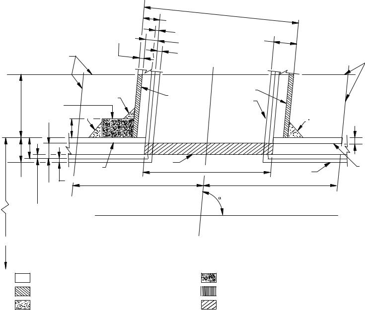
(D.2) Figure 104.3.1(D) illustrates the notations used in the pressure–temperature design conditions of branch connections. These notations are as follows:
b p subscript referring to branch
Dob p outside diameter of branch, in. (mm) Doh p outside diameter of header, in. (mm)
d1 p inside centerline longitudinal dimension of the finished branch opening in the run of the pipe, in. (mm)
p [Dob − 2(Tb − A)]/sin
d2 p “half width” of reinforcing zone, in. (mm)
pthe greater of d1 or (Tb − A) + (Th − A) + d1/2 but in no case more than Doh, in. (mm)
h p subscript referring to run or header
L4 p altitude of reinforcement zone outside of run, in. (mm)
p2.5(Tb − A) + tr or 2.5(Th − A), whichever is smaller
tr p thickness of attached reinforcing pad, in Example A, in. (mm); or height of the largest 60 deg right triangle supported by the run and branch outside diameter projected surfaces and lying completely within the area of integral reinforcement, in Example B, in. (mm)
Tb, Th p actual (by measurement), or minimum wall thickness of the branch or header pipe, in. (mm), permissible under purchase specification
tmb, tmh p required minimum wall thickness, in. (mm), of the branch or header pipe as determined by use of eq. (7) or (8) in para. 104.1.2(A)
p angle between axes of branch and run, deg
-- Copyright ASME International
Provided by IHS under license`,,```````,,```, with ASME
No reproduction or networking permitted without license from IHS
reproduction No |
IHS by Provided |
ASME Copyright |
networking or |
license under |
International |
without permitted |
ASME with |
|
IHS from license |
|
|
24
Fig. 104.3.1(D) Reinforcement of Branch Connections
|
|
Dob |
|
|
Tb |
|
|
Excess wall |
Additional |
Nominal |
|
in branch |
thickness, A |
||
|
tmb |
thickness |
|
Reinforcement |
Mill tolerance |
Reinforcement |
|
zone |
|||
|
|||
|
zone |
||
|
|
|
|
|
|
A2 |
Branch without |
|
|
|
A3 |
A2 |
reinforcement |
|
|
|
|
Branch pipe |
|
|||
|
|
(for saddle |
|
|||
L4 |
Ring or pad, A4 |
|
|
or nozzle |
|
|
|
|
see Detail on |
|
|||
|
[Notes (1) and (2)] |
A3 |
|
|
next page) |
Excess wall |
|
|
|
|
|||
|
tr |
|
|
|
A3 |
in header |
|
|
|
|
|
|
Th |
|
|
|
|
|
|
|
|
|
A1 |
|
A6 |
d1 |
|
A1 |
|
|
|
|
Header or |
|||
Nominal |
|
Mill tolerance |
d2 |
|
|
run pipe |
|
tmh |
|
|
d2 |
|
|||
thickness |
|
|
|
|
|
|
|
Additional |
|
|
Run or header |
|
|
|
|
thickness, |
A |
c |
|
|
|
||
[see para. |
|
L |
|
|
|
||
|
|
|
|
|
|
||
104.1.2(A.6)] |
|
|
|
Branch |
|
||
|
|
|
|
L |
|
|
|
Doh |
|
|
|
c |
|
|
|
|
|
|
|
|
|
|
|
|
|
|
|
Example A |
|
|
|
Explanation of areas: |
|
|
|
|
|
||
Area A1 — available reinforcement area (excess wall) in header |
|
Area A4 — metal in ring, pad, or integral reinforcement |
|
||||
Area A2 — available reinforcement area (excess wall) in branch |
|
Area A5 — metal in saddle parallel to run (see Detail) |
|
||||
Area A3 — available reinforcement area fillet weld metal |
|
Area A6 — pressure design area (expected |
|
||||
|
|
|
|
|
|
at the end of service life) |
|
2010-1.B31 ASME
--`,,```````,,```,`,`,,,,`,`,`,`-`-`,,`,,`,`,,`---
reproduction No |
IHS by Provided |
ASME Copyright |
networking or |
license under |
International |
without permitted |
ASME with |
|
IHS from license |
|
|
25 ---`,,`,,`,`,,`-`-`,,```````,,```,`,`,,,,`,`,`,`--
|
|
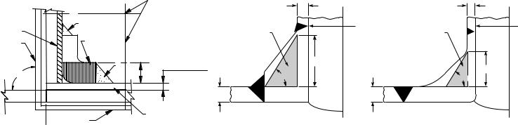
Fig. 104.3.1(D) Reinforcement of Branch Connections (Cont’d) |
|
|
|||
|
Reinforcement |
|
|
|
|
|
|
|
zone |
|
|
Tb |
|
|
Tb |
|
|
|
|
|
|
||
A2 |
A3 |
|
|
Reinforcement |
d1 |
Reinforcement |
d1 |
Saddle, A5 |
|
|
|||||
Branch pipe |
|
|
area |
|
area |
|
|
[Note (3)] |
|
|
|
|
|||
or nozzle |
|
|
|
|
|
|
|
|
|
|
|
|
|
|
|
|
A3 |
|
Excess wall |
tr |
|
|
|
|
|
in header |
|
|
tr |
||
90 deg |
tr |
60 deg |
|
|
|||
|
|
|
|
60 deg |
|||
|
|
|
|
|
|
||
|
|
|
|
Th |
Th |
|
|
|
Header or |
A1 |
|
(a) |
|
(b) |
|
|
run pipe |
|
|
|
|
||
|
|
|
|
|
|
|
|
|
Detail |
|
|
|
|
|
|
|
for Example A |
|
|
|
Example B |
|
|
GENERAL NOTES:
(a)This Figure illustrates the nomenclature of para. 104.3.1(D).
(b)Required reinforcement area p A7 p A6 (2 − sin ) p (tmh − A)dt (2 − sin ).
(c)Available reinforcement areas p A1 + A2 + A3 + A4 + A5 (as applicable).
(d)Available reinforcement areas ≥ required reinforcement area.
NOTES:
(1)When a ring or pad is added as reinforcement (Example A), the value of reinforcement area may be taken in the same manner in which excess header metal is considered, provided the weld completely fuses the branch pipe, header pipe, and ring or pad. Typical acceptable methods of welding which meet the above requirement are shown in Fig. 127.4.8(D), sketches (c) and (d).
(2)Width to height of rings and pads shall be reasonably proportioned, preferably on a ratio as close to 4:1 as the available horizontal space within the limits of the reinforcing zone along the run and the outside diameter of the branch will permit, but in no case may the ratio be less than 1:1.
(3)Reinforcement saddles are limited to use on 90 deg branches (Example A Detail).
2010-1.B31 ASME
ASME B31.1-2010
(D.2.1) If the run pipe contains a longitudinal seam that is not intersected by the branch, the stress value of seamless pipe of comparable grade may be used to determine the value of tmh for the purpose of reinforcement calculations only. If the branch intersects a longitudinal weld in the run, or if the branch contains a weld, the weld joint efficiency for either or both shall enter the calculations. If the branch and run both contain longitudinal welds, care shall be taken to ensure that the two welds do not intersect each other.
(D.2.2) The required reinforcement area in square inches (square millimeters) for branch connections shall be the quantity
A7 p A6(2 − sin ) p (tmh − A)d1 (2 − sin )
For right angle connections, the required reinforcement becomes
A7 p A6 p (tmh − A)d1
The required reinforcement must be within the limits of the reinforcement zone as defined in (D.2.4) below.
(D.2.3) The reinforcement required by (D.2) shall be that provided by any combination of areas A1, A2, A3, A4, and A5, as defined below and illustrated in Fig. 104.3.1(D) where
A1 p area provided by excess pipe wall in the run
p (2d2 − d1)(Th − tmh)
A2 p area, in.2 (mm2), provided by excess pipe wall in the branch for a distance L4 above the run
p 2L4 (Tb − tmb)/sin
A3 p area provided by deposited weld metal beyond the outside diameter of the run and branch, and for fillet weld attachments of rings, pads, and saddles
A4 p area provided by a reinforcing ring, pad, or integral reinforcement. The value of A4 may be taken in the same manner in which excess header metal is considered, provided the weld completely fuses the branch pipe, run pipe, and ring or pad, or integral reinforcement. For welding branch connections refer to para. 127.4.8.
A5 p area provided by a saddle on right angle connections
p (O.D. of saddle − Dob)tr
A6 p pressure design area expected at the end of service life
p (tmh − A)d1
Portions of the reinforcement area may be composed of materials other than those of the run pipe, but if the allowable stress of these materials is less than that for the run pipe, the corresponding calculated reinforcement area provided by this material shall be reduced in the ratio of the allowable stress being applied to the reinforcement area. No additional credit shall be taken for materials having higher allowable stress values than the run pipe.
(D.2.4) Reinforcement Zone. The reinforcement zone is a parallelogram whose width shall extend a distance d2 on each side of the centerline of the branch pipe, and whose altitude shall start at the inside surface of the run pipe and extend to a distance L4 from the outside surface of the run pipe.
(D.2.5) Reinforcement of Multiple Openings. It is preferred that multiple branch openings be spaced so that their reinforcement zones do not overlap. If closer spacing is necessary, the following requirement shall be met. The two or more openings shall be reinforced in accordance with (D.2), with a combined reinforcement that has a strength equal to the combined strength of the reinforcement that would be required for the separate openings. No portion of the cross section shall be considered as applying to more than one opening, or be evaluated more than once in a combined area.
When more than two adjacent openings are to be provided with a combined reinforcement, the minimum distance between centers of any two of these openings should preferably be at least 11⁄2 times their average diameter, and the area of reinforcement between them shall be at least equal to 50% of the total required for these two openings.
(D.2.6) Rings, Pads, and Saddles. Reinforcement provided in the form of rings, pads, or saddles shall not be appreciably narrower at the side than at the crotch.
A vent hole shall be provided at the ring, pad, or saddle to provide venting during welding and heat treatment. Refer to para. 127.4.8(E).
Rings, pads, or saddles may be made in more than one piece, provided the joints between pieces have full thickness welds, and each piece is provided with a vent hole.
(D.2.7) Other Designs. The adequacy of designs to which the reinforcement requirements of para. 104.3 cannot be applied shall be proven by burst or proof tests on scale models or on full size structures, or by calculations previously substantiated by successful service of similar design.
(E) Branch Connections Subject to External Pressure Requiring Reinforcement. The reinforcement area in square inches (square millimeters) required for branch connections subject to external pressure shall be
0.5tmhd1 (2 − sin )
where tmh is the required header wall thickness determined for straight pipe under external pressure, using procedures outlined in UG-28, UG-29, UG-30, and UG-31 of Section VIII, Division 1, of the ASME Boiler and Pressure Vessel Code.
Procedures established heretofore for connections subject to internal pressure shall apply for connections subject to external pressure provided that Doh, Dob, and tr are reduced to compensate for external corrosion, if required by design conditions.
26
--`,,```````,,```,`,`,,,,`,`,`,`-`-`,,`,,`,`,,`---
Copyright ASME International
Provided by IHS under license with ASME
No reproduction or networking permitted without license from IHS

---`,,`,,`,`,,`-`-`,,```````,,```,`,`,,,,`,`,`,`--
ASME B31.1-2010
(F)Branch Connections Subject to External Forces and Moments. The requirements of the preceding paragraphs are intended to ensure safe performance of a branch connection subjected only to pressure. However, when external forces and moments are applied to a branch connection by thermal expansion and contraction, by dead weight of piping, valves, and fittings, covering and contents, or by earth settlement, the branch connection shall be analyzed considering the stress intensification factors as specified in Appendix D. Use of ribs, gussets, and clamps designed in accordance with para. 104.3.4 is permissible to stiffen the branch connection, but their areas cannot be counted as contributing to the required reinforcement area of the branch connection.
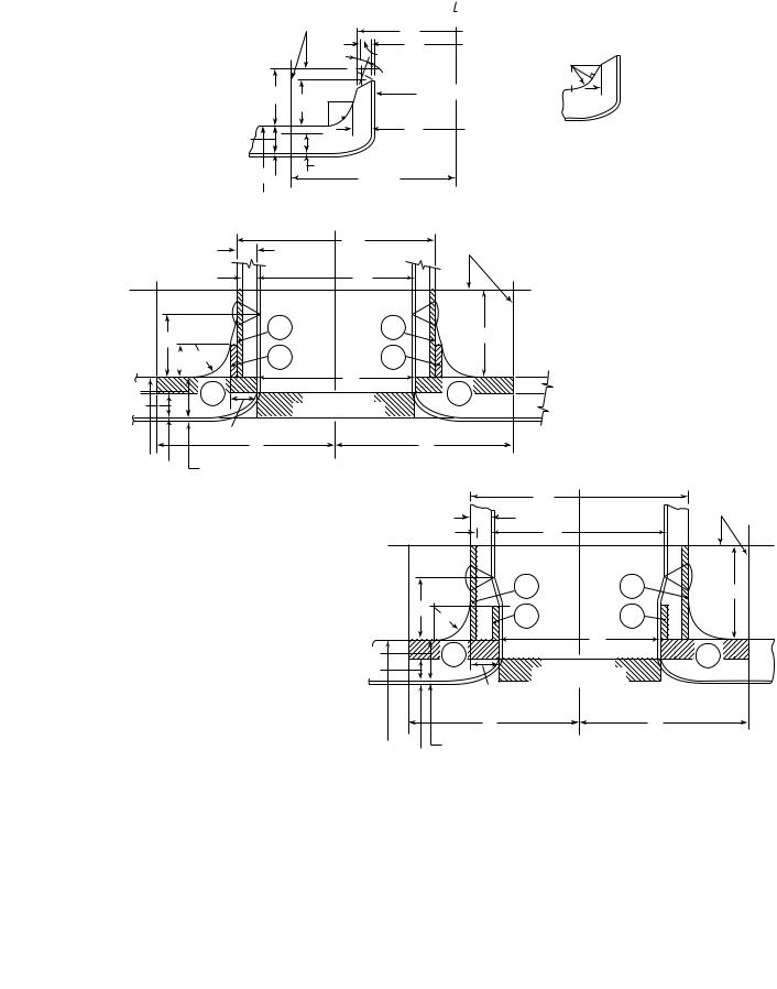
(G)Extruded Outlets Integrally Reinforced
(G.1) The following definitions, modifications, notations, and requirements are specifically applicable to extruded outlets. The designer shall make proper wall thickness allowances in order that the required minimum reinforcement is ensured over the design life of the system.
(G.2) Definition. An extruded outlet header is defined as a header in which the extruded lip at the outlet has an altitude above the surface of the run that is equal to or greater than the radius of curvature of the external contoured portion of the outlet; i.e., ho ≥ ro. See nomenclature and Fig. 104.3.1(G).
(G.3) These rules apply only to cases where the axis of the outlet intersects and is perpendicular to the axis of the run. These rules do not apply to any nozzle in which additional nonintegral material is applied in the form of rings, pads, or saddles.
(G.4) The notation used herein is illustrated in Fig. 104.3.1(G). All dimensions are in inches (millimeters).
Dob p outside diameter of branch pipe Doh p outside diameter of run
db p corroded internal diameter of branch pipe dc p corroded internal diameter of extruded outlet measured at the level of the outside
surface of the run
dr p corroded internal diameter of run
ho p height of the extruded lip. This must be equal to or greater than ro, except as shown in (G.4.2) below.
L8 p altitude of reinforcement zone
p 0.7 DobTo
To p corroded finished thickness of extruded outlet measured at a height equal to ro above the outside surface of the run
tb − A p actual thickness of branch wall, not including corrosion allowance
th − A p actual thickness of run wall, not including the corrosion allowance
tmb − A p required thickness of branch pipe according to wall thickness eq. (7) or (8) in para. 104.1.2(A), but not including any thickness for corrosion
tmh − A p required thickness of the run according to eq. (7) or (8) in para. 104.1.2(A), but not including any allowance for corrosion
r1 p half width of reinforcement zone (equal to dc)
ro p radius of curvature of external contoured portion of outlet measured in the plane containing the axes of the run and branch. This is subject to the following limitations:
(G.4.1) Minimum Radius. This dimension shall not be less than 0.05Dob except that on branch diameters larger than NPS 30, it need not exceed 1.50 in. (38 mm).
(G.4.2) Maximum Radius. For outlet pipe sizes 6 in. (150 mm) nominal and larger, this dimension shall not exceed 0.10Dob + 0.50 in. (0.10Dob + 12.7 mm). For outlet pipe sizes less than NPS 6, this dimension shall be not greater than 1.25 in. (32 mm).
(G.4.3) When the external contour contains more than one radius, the radius of any arc sector of approximately 45 deg shall meet the requirements of (G.4.1) and (G.4.2) above. When the external contour has a continuously varying radius, the radius of curvature at every point on the contour shall meet the requirements of (G.4.1) and (G.4.2) above.
(G.4.4) Machining other than grinding for weld cleanup shall not be employed in order to meet the above requirements.
(G.5) Required Area. The required area is defined as
A7 p K (tmh − A) dc
where K shall be taken as follows:
For Dob/Doh greater than 0.60,
K p 1.00
For Dob/Doh greater than 0.15 and not exceeding 0.60,
K p 0.6 + 2⁄3 Dob/Doh
For Dob/Doh equal to or less than 0.15,
K p 0.70
The design must meet criteria that the reinforcement area defined in (G.6) below is not less than the required area.
27
Copyright ASME International
Provided by IHS under license with ASME
No reproduction or networking permitted without license from IHS
ASME B31.1-2010
Fig. 104.3.1(G) Reinforced Extruded Outlets
Limits of |
c |
reinforcement zone |
of branch |
|
|
|
|
|
30 deg |
Dob |
|
|
|
|
|
|
db |
|
|
|
|
|
|
|
max. |
(tmb − A) |
|
|
|
|
|
|
|
|
ro |
|
|
|
L8 |
ho |
ro |
|
See Note (1) |
|
|
|
|
|
|
||
|
|
|
|
|
|
|
|
|
|
(th − A) |
|
|
To |
dc |
|
|
|
|
|
(tmh − A) |
|
|
|
|
|
Doh |
|
|
Allowance |
= dc |
|
|
|
dr |
|
r1 |
|
||
|
|
|
|
|
|||
|
|
|
|
|
|
|
|
|
|
|
|
|
(a) |
|
|
|
|
|
|
|
Dob |
|
Reinforcement |
|
(tb − A) |
|
|
|
zone |
||
|
|
|
|
|
|||
|
(tmb − A) |
|
|
db |
|
|
|
|
ho |
|
A2 |
|
|
A2 |
L8 |
|
ro |
|
|
|
|
||
|
ro |
A4 |
|
|
A4 |
|
|
(th − A) |
|
A1 |
|
|
dc |
|
A1 |
|
|
Required area |
|
||||
(tmh − A) |
|
|
|
|
|
||
|
|
|
A7 = K (tmh − A) dc |
|
|||
|
|
To |
|
|
|
|
r1 |
|
|
r1 |
|
|
|
|
|
Doh |
dr |
Allowance |
|
|
|
|
|
To  See Note (2)
(b)
(c) See Note (3) |
|
|
|
Dob |
|
Reinforcement |
|
|
|
|
|
||
|
|
|
|
|
zone |
|
|
(tb − A) |
|
|
|
||
|
|
db |
|
|
||
|
(tmb − A) |
|
|
|
||
|
|
|
A2 |
|
A2 |
L8 |
|
|
|
|
|
|
|
|
ho |
ro |
A4 |
|
A4 |
|
(th − A) |
|
A1 |
|
dc |
|
A1 |
|
|
Required area |
|
|||
(tmh − A) |
|
|
|
|
|
|
|
|
|
A7 = K (tmh − A) dc |
|
|
|
|
|
To |
|
|
|
|
|
|
r1 |
|
|
|
r1 |
Doh |
dr |
Allowance |
|
|
|
|
|
|
|
|
|
|
|
(d) See Note (3)
NOTES:
(1)Taper bore inside diameter (if required) to match branch pipe 1:3 maximum taper.
(2)Sketch to show method of establishing To when the taper encroaches on the crotch radius.
(3)Sketch is drawn for condition where k p 1.00.
28
--`,,```````,,```,`,`,,,,`,`,`,`-`-`,,`,,`,`,,`---
Copyright ASME International
Provided by IHS under license with ASME
No reproduction or networking permitted without license from IHS
ASME B31.1-2010
(G.6) Reinforcement Area. The reinforcement area shall be the sum of areas
A1 + A2 + A4
as defined below.
(G.6.1) Area A1 is the area lying within the reinforcement zone resulting from any excess thickness available in the run wall.
A1 p dc(tn − tmh)
(G.6.2) Area A2 is the area lying within the reinforcement zone resulting from any excess thickness available in the branch pipe wall.
A2 p 2L8(tb − tmb)
(G.6.3) Area A4 is the area lying within the reinforcement zone resulting from excess thickness available in the extruded outlet lip.
A4 p 2ro [To − (tb − A)]
(G.7) Reinforcement of Multiple Openings. It is preferred that multiple branch openings be spaced so that their reinforcement zones do not overlap. If closer spacing is necessary, the following requirements shall be met. The two or more openings shall be reinforced in accordance with (G) with a combined reinforcement that has a strength equal to the combined strength of the reinforcement that would be required for separate openings. No portion of the cross section shall be considered as applying to more than one opening, or be evaluated more than once in a combined area.
(G.8) In addition to the above, the manufacturer shall be responsible for establishing and marking on the section containing extruded outlets, the design pressure and temperature. The manufacturer’s name or trademarks shall be marked on the section.
104.3.3 Miters. Miter joints, and the terminology related thereto, are described in Appendix D. A widely spaced miter with
< 9 tn deg r
shall be considered to be equivalent to a girth buttwelded joint, and the rules of this paragraph do not apply. Miter joints, and fabricated pipe bends consisting of segments of straight pipe welded together, with equal to or greater than this calculated value may be used within the limitations described below.
(A) Pressure shall be limited to 10 psi (70 kPa) under the following conditions:
(A.1) The assembly includes a miter weld with > 22.5 deg, or contains a segment that has a dimension
B < 6tn
(A.2) The thickness of each segment of the miter is not less than that determined in accordance with para. 104.1.
(A.3) The contained fluid is nonflammable, nontoxic, and incompressible, except for gaseous vents to atmosphere.
(A.4) The number of full pressure cycles is less than 7,000 during the expected lifetime of the piping system.
(A.5) Full penetration welds are used in joining miter segments.
(B) Pressure shall be limited to 100 psi (700 kPa) under the conditions defined in (A.2), (A.3), (A.4), and (A.5) above, in addition to the following:
(B.1) the angle does not exceed 22.5 deg
(B.2) the assembly does not contain any segment that has a dimension
B< 6tn
(C)Miters to be used in other services or at design pressures above 100 psi (700 kPa) shall meet the requirements of para. 104.7.
(C.1) When justification under para. 104.7 is based on comparable service conditions, such conditions must be established as comparable with respect to cyclic as well as static loadings.
(C.2) When justification under para. 104.7 is based on an analysis, that analysis and substantiating tests shall consider the discontinuity stresses that exist at the juncture between segments; both for static (including brittle fracture) and cyclic internal pressure.
(C.3) The wall thickness, ts, of a segment of a miter shall not be less than specified in (C.3.1) or (C.3.2) below, depending on the spacing.
(C.3.1) For closely spaced miter bends (see Appendix D for definition)
2 − r/R ts p tm 2(1 − r/R)
(C.3.2) For widely spaced miters (see Appendix D for definition)
ts p tm(1 + 0.64 r/ts tan )
(The above equation requires an iterative or quadratic solution for ts.)
104.3.4 Attachments. External and internal attachments to piping shall be designed so as not to cause flattening of the pipe, excessive localized bending stresses, or harmful thermal gradients in the pipe wall. It is important that such attachments be designed to minimize stress concentrations in applications where the number of stress cycles, due either to pressure or thermal effect, is relatively large for the expected life of the equipment.
--`,,```````,,```,`,`,,,,`,`,`,`-`-`,,`,,`,`,,`---
29
Copyright ASME International
Provided by IHS under license with ASME
No reproduction or networking permitted without license from IHS
ASME B31.1-2010
104.4Closures
104.4.1General. Closures for power piping systems shall meet the applicable requirements of this Code and shall comply with the requirements described in
(A) or (B) below. Closures may be made
(A)by use of closure fittings, such as threaded or welded plugs, caps, or blind flanges, manufactured in accordance with standards listed in Table 126.1, and used within the specified pressure–temperature ratings, or
(B)in accordance with the rules contained in the ASME Boiler and Pressure Vessel Code, Section I, Power Boilers, PG-31, or Section VIII, Pressure Vessels, Division 1, UG-34 and UW-13, calculated from
tm p t + A
where
tp pressure design thickness, calculated for the given closure shape and direction of loading using appropriate equations and procedures in Section I or Section VIII, Division 1 of the ASME Boiler and Pressure Vessel Code
The definition of A and the symbols used in determining t shall have the definitions shown herein, instead of those given in the ASME Boiler and Pressure Vessel Code.
Attachment of a welded flat permanent closure with only a single fillet weld is not permitted.
104.4.2 Openings in Closures. Openings in closures may be made by welding, extruding, or threading. Attachment to the closure shall be in accordance with the limitations provided for such connections in para. 104.3.1 for branch connections. If the size of the opening is greater than one-half of the inside diameter of the closure,-- the opening shall be designed as a reducer in accordance with para. 104.6.
Other openings in closures shall be reinforced in accordance with the requirements of reinforcement for a
branch connection. The total cross-sectional area |
|
-`-`,,```````,,```,`,`,,,,`,`,`,` |
|
required for reinforcement in any plane passing through |
|
the---`,,`,,`,`,,` |
closure shall not be less than the quantity of d5t, |
the center of the opening and normal to the surface of where
d5 p diameter of the finished opening, in. (mm) t p as defined in (B) above
104.5Pressure Design of Flanges and Blanks
104.5.1Flanges — General
(A) Flanges of sizes NPS 24 and smaller, that are manufactured in accordance with ASME B16.1 and B16.5, shall be considered suitable for use at the primary service ratings (allowable pressure at service temperature) except the slip-on flanges to ASME B16.5 shall be limited
in application to no higher than Class 300 primary pressure service rating. Refer to para. 127.4.4.
For flanges larger than NPS 24, and manufactured in accordance with the Specifications and Standards listed in Table 126.1, the designer is cautioned about the dimensionally different designs that are available, as well as the limitations of their application.
Flanges not made in accordance with the Specifications and Standards listed in Table 126.1 shall be designed in accordance with Section VIII, Division 1 of the ASME Boiler and Pressure Vessel Code, except that the requirements for fabrication, assembly, inspection, and testing, and the pressure and temperature limits for materials of this Code for Pressure Piping shall govern. Certain notations used in the ASME Code, namely, P, Sa, Sb, and Sf, shall have the meanings described below instead of those given in the ASME Code. All other notations shall be as defined in the ASME Code.
P p design pressure, psi (kPa) (see paras. 101.2.2 and 101.2.4)
Sa p bolt design stress at atmospheric temperature, psi (kPa)
Sb p bolt design stress at design temperature, psi (kPa)
Sf p allowable stress for flange material or pipe, psi (kPa) (see para. 102.3.1 and Allowable Stress Tables) (stress values converted from MPa to kPa)
For certain specific applications, see the limitations of paras. 122.1.1(F), (G), and (H).
(B)These flange design rules are not applicable to flat face designs employing full face gaskets that extend beyond the bolts.
(C)The bolt design stress in (A) above shall be as established in Section VIII, Division 1 of the ASME Boiler and Pressure Vessel Code, Appendix P for ferrous materials.
(D)Application of bolting materials for flanged joints is covered in para. 108.5.
104.5.2Blind Flanges
(A)Blind flanges manufactured in accordance with the standards listed in Table 126.1 shall be considered suitable for use at the pressure–temperature rating specified by such standards.
(B)The required thickness of blind flanges not manufactured in accordance with standards in Table 126.1 shall be calculated from eq. (13).
tm p t + A |
(13) |
where
t p pressure design thickness as calculated for the given style of blind flange from the appropriate equations for bolted flat cover plates in Section I of the ASME Boiler and Pressure Vessel Code. Certain notations used in these equations,
30
Copyright ASME International
Provided by IHS under license with ASME
No reproduction or networking permitted without license from IHS
ASME B31.1-2010
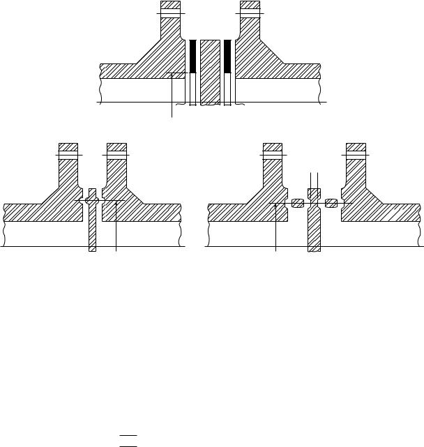
Fig. 104.5.3 Types of Permanent Blanks
d6
 t
t 
---`,,`,,`,`,,`-`-`,,```````,,```,`,`,,,,`,`,`,`--
d6 |
d6 |
namely, P and SE [see para. 104.1.2(A), footnote 3], shall be considered to have the meanings described in para. 104.1.2(A) instead of those given in the ASME Code. All other notations shall be as defined in the ASME Code.
104.5.3Blanks
(A)The required thickness of permanent blanks (see Fig. 104.5.3) shall be calculated from the equation
tm p t + A
where
t p pressure design thickness as calculated from eq. (14)
3P |
|
t p d6 16SE |
(14) |
See para. 104.1.2(A), footnote 3.
d6 p inside diameter of gasket for raised or flat (plain) face flanges, or the gasket pitch diameter for retained gasketed flanges, in. (mm)
(B) Blanks to be used for test purposes only shall have a minimum thickness not less than the pressure design thickness t specified above except that P shall be not less than the test pressure and SE [see para. 104.1.2(A), footnote 3] may be taken as the specified minimum yield strength of the blank material if the test fluid is incompressible.
(C) Attachment of a welded flat permanent blank with only a single fillet weld is not permitted.
104.6 Reducers
Flanged reducer fittings manufactured in accordance with the Standards listed in Table 126.1 shall be considered suitable for use at the specified pressure– temperature ratings. Where butt welding reducers are made to a nominal pipe thickness, the reducers shall be considered suitable for use with pipe of the same nominal thickness.
104.7Other Pressure-Containing Components
104.7.1Pressure-containing components manufactured in accordance with the standards listed in Table 126.1 shall be considered suitable for use under normal operating conditions at or below the specified pressure–temperature ratings. However, the user is cautioned that where certain standards or manufacturers may impose more restrictive allowances for variation from normal operation than those established by this Code, the more restrictive allowances shall apply.
104.7.2Specially Designed Components. The pressure design of components not covered by the standards listed in Table 126.1 or for which design formulas and procedures are not given in this Code shall be based on calculations consistent with the design criteria of this Code. These calculations shall be substantiated by one
31
Copyright ASME International |
|
Provided by IHS under license with ASME |
|
No reproduction or networking permitted without license from IHS |
Not for Resale, 03/08/2011 00:55:16 MST |
ASME B31.1-2010
or more of the means stated in (A), (B), (C), and (D) below.
(A)extensive, successful service experience under comparable conditions with similarly proportioned components of the same or similar material
(B)experimental stress analysis, such as described in the ASME Boiler and Pressure Vessel Code, Section VIII, Division 2, Appendix 6
(C)proof test in accordance with either ASME B16.9; MSS SP-97; or the ASME Boiler and Pressure Vessel Code, Section I, A-22
(D)detailed stress analysis, such as finite element method, in accordance with the ASME Boiler and Pressure Vessel Code, Section VIII, Division 2, Appendix 4, except that the basic material allowable stress from the Allowable Stress Tables of Appendix A shall be used in place of Sm
For any of (A) through (D) above, it is permissible to interpolate between sizes, wall thicknesses, and pressure classes and to determine analogies among related materials.
Calculations and documentation showing compliance with this paragraph shall be available for the owner’s approval, and, for boiler external piping, they shall be available for the Authorized Inspector’s review.
-- |
104.8 Analysis of Piping Components |
|
-`-`,,```````,,```,`,`,,,,`,`,`,` |
||
other sustained loads, and other occasional loads. Each |
||
|
To validate a design under the rules in this paragraph, |
|
|
the complete piping system must be analyzed between |
|
`,,`,,`,`,,` |
anchors for the effects of thermal expansion, weight, |
|
paragraph. For pipe and fittings, the pressure term in |
||
|
component in the system must meet the limits in this |
|
--- |
eqs. (15) and (16) may be replaced with the alternative |
|
|
||
|
term for Slp as defined in para. 102.3.2(D). The pressure |
|
|
term in eqs. (15) and (16) may not apply for bellows |
|
|
and expansion joints. When evaluating stresses in the |
|
|
vicinity of expansion joints, consideration must be given |
|
|
to actual cross-sectional areas that exist at the expan- |
|
|
sion joint. |
|
|
104.8.1 Stress Due to Sustained Loads. The effects |
|
|
of pressure, weight, and other sustained mechanical |
|
|
loads shall meet the requirements of eq. (15). |
|
|
(U.S. Customary Units) |
where
ip stress intensification factor (see Appendix D). The product 0.75i shall never be taken as less than 1.0.
MA p resultant moment loading on cross section due to weight and other sustained loads, in-lb (mm-N) (see para. 104.8.4)
Sh p basic material allowable stress at maximum (hot) temperature [see para. 102.3.2(D)]
SL p sum of the longitudinal stresses due to pressure, weight, and other sustained loads
Z p section modulus, in.3 (mm3) (see para. 104.8.4)
104.8.2 Stress Due to Occasional Loads. The effects of pressure, weight, other sustained loads, and occasional loads including earthquake shall meet the requirements of eq. (16).
(U.S. Customary Units)
|
|
PDo |
+ |
0.75iMA |
+ |
0.75iMB |
≤ kSh |
(16) |
||||
|
|
Z |
|
|
||||||||
|
|
4tn |
|
|
|
Z |
|
|||||
(SI Units) |
|
|
|
|
|
|
|
|
|
|||
|
PDo |
+ |
0.75iMA |
+ |
0.75iMB |
≤ kSh |
|
|||||
(1 000)4tn |
Z |
|
|
|
||||||||
|
|
|
Z |
|
||||||||
Terms same as para. 104.8.1, except
k p 1.15 for occasional loads acting for no more than 8 hr at any one time and no more than 800 hr/yr [see para. 102.3.3(A)]
p1.2 for occasional loads acting for no more than 1 hr at any one time and no more than 80 hr/yr [see para. 102.3.3(A)]
MB p resultant moment loading on the cross section due to occasional loads, such as thrusts from relief/safety valve loads, from pressure and flow transients, and earthquake, in.-lb (mm-N) [see paras. 102.3.3(A) and 104.8.4]
104.8.3 Stress Due to Displacement Load Ranges.
The effects of thermal expansion and other cyclic loads shall meet the requirements of eq. (17).
(U.S. Customary Units)
SE p |
iMC |
≤ SA |
(17) |
|
|||
|
Z |
|
|
(SI Units)
|
PDo |
|
0.75iMA |
≤ 1.0 Sh |
|
SE p |
1 000(iMC) |
≤ SA |
|
SL p |
+ |
(15) |
Z |
||||||
|
|
|
|
||||||
|
4tn |
Z |
|
|
|
|
|||
(SI Units) |
|
|
|
|
|
|
Terms same as para. 104.8.1, except |
|
|
|
|
|
|
MC p resultant moment loading range on the cross |
|
|
|
|
|
|
|
|
section due to the reference displacement load |
SL p |
PDo |
|
+ |
|
0.75iMA |
≤ 1.0 Sh |
range. For flexibility analyses, the resultant |
|
|
moment due to the ambient to normal |
|||||
(1 000)4tn |
|
||||||
|
|
|
Z |
||||
|
|
|
|
|
|
|
32 |
Copyright ASME International
Provided by IHS under license with ASME
No reproduction or networking permitted without license from IHS