

ASME B31.1-2010
devices used to attach the counterweight load to the piping, shall be subject to requirements of para. 121.7.2.
(C) Hydraulic type supports utilizing a hydraulic head may be installed to give a constant supporting effort. Safety devices and stops shall be provided to support the load in case of hydraulic failure.
(D) Boosters may be used to supplement the operation of constant support hangers.
121.7.5 Sway Braces. Sway braces or vibration dampeners shall be used to control the movement of piping due to vibration.
-- 121.7.6 Shock Suppressors. For the control of pip- |
|
121.8-`-`,,```````,,```,`,`,,,,`,`,`,` |
Structural Attachments |
ing due to dynamic loads, hydraulic or mechanical types of shock suppressors are permitted. These devices do not support pipe weight.
`,,`,,`,`,,`--- (A) Nonintegral attachments include clamps, slings, cradles, saddles, straps, and clevises.
(B) When clamps are used to support vertical lines, it is recommended that shear lugs be welded to the pipe to prevent slippage. The provisions of para. 121.8.2(B) shall apply.
(C) In addition to the provision of (B) above, clamps to support vertical lines should be designed to support the total load on either arm in the event the load shifts due to pipe and/or hanger movement.
121.8.2Integral Type
(A)Integral attachments include ears, shoes, lugs, cylindrical attachments, rings, and skirts that are fabricated so that the attachment is an integral part of the piping component. Integral attachments shall be used in conjunction with restraints or braces where multiaxial restraint in a single member is to be maintained. Consideration shall be given to the localized stresses induced into the piping component by the integral attachments. Where applicable, the conditions of para. 121.8.1(C) are to apply.
(B)Integral lugs, plates, angle clips, etc., used as part of an assembly for the support or guiding of pipe may be welded directly to the pipe provided the materials are compatible for welding and the design is adequate for the temperature and load. The design of hanger lugs for attachment to piping for high temperature service shall be such as to provide for differential expansion between the pipe and the attached lug.
121.9Loads and Supporting Structures
Considerations shall be given to the load carrying capacity of equipment and the supporting structure. This may necessitate closer spacing of hangers on lines with extremely high loads.
121.10 Requirements for Fabricating Pipe Supports
Pipe supports shall be fabricated in accordance with the requirements of para. 130.
PART 6
SYSTEMS
122DESIGN REQUIREMENTS PERTAINING TO SPECIFIC PIPING SYSTEMS
Except as specifically stated otherwise in this Part 6, all provisions of the Code apply fully to the piping systems described herein.
122.1Boiler External Piping; in Accordance With Para. 100.1.2(A) — Steam, Feedwater, Blowoff, and Drain Piping
122.1.1General. The minimum pressure and temperature and other special requirements to be used in the design for steam, feedwater, blowoff, and drain piping from the boiler to the valve or valves required by para. 122.1 shall be as specified in the following paragraphs. Design requirements for desuperheater spray piping connected to desuperheaters located in the boiler proper and in main steam piping are provided in para. 122.4.
(A) It is intended that the design pressure and temperature be selected sufficiently in excess of any expected operating conditions, not necessarily continuous, to permit satisfactory operation without operation of the overpressure protection devices. Also, since the operating temperatures of fired equipment can vary, the expected temperature at the connection to the fired equipment shall include the manufacturer’s maximum temperature tolerance.
(B) In a forced flow steam generator with no fixed steam and water line, it is permissible to design the external piping, valves, and fittings attached to the pressure parts for different pressure levels along the path through the steam generator of water-steam flow. The values of design pressure and the design temperature to be used for the external piping, valves, and fittings shall be not less than that required for the expected maximum sustained operating pressure and temperature to which the abutted pressure part is subjected except when one or more of the overpressure protection devices covered by PG-67.4 of Section I of the ASME Boiler and Pressure Vessel Code is in operation. The steam piping shall comply with the requirements for the maximum sustained operating conditions as used in (A) above, or for the design throttle pressure plus 5%, whichever is greater.
(C) Provision shall be made for the expansion and contraction of piping connected to boilers to limit forces and moments transmitted to the boiler, by providing substantial anchorage at suitable points, so that there shall be no undue strain transmitted to the boiler. Steam
50
Copyright ASME International
Provided by IHS under license with ASME
No reproduction or networking permitted without license from IHS
ASME B31.1-2010
reservoirs shall be used on steam mains when heavy pulsations of the steam currents cause vibration.
(D)Piping connected to the outlet of a boiler for any purpose shall be attached by
(D.1) welding to a nozzle or socket welding fitting
(D.2) threading into a tapped opening with a threaded fitting or valve at the other end
(D.3) screwing each end into tapered flanges, fittings, or valves with or without rolling or peening
(D.4) bolted joints including those of the Van Stone type
(D.5) blowoff piping of firetube boilers shall be attached in accordance with (D.2) above if exposed to products of combustion or in accordance with (D.2), (D.3), or (D.4) above if not so exposed
(E)Nonferrous pipe or tubes shall not exceed NPS 3 in diameter.
(F)American National Standard slip-on flanges shall not exceed NPS 4. Attachment of slip-on flanges shall be by double fillet welds. The throats of the fillet welds shall not be less than 0.7 times the thickness of the part to which the flange is attached.
(G)Hub-type flanges shall not be cut from plate material.
(H)American National Standard socket welded flanges may be used in piping or boiler nozzles provided
the dimensions do not exceed NPS 3 for Class 600 and lower and NPS 21⁄2 in Class 1500.
122.1.2Steam Piping
(A)The value of P to be used in the formulas in para. 104 shall be as follows:
(A.1) For steam piping connected to the steam drum or to the superheater inlet header up to the first stop valve in each connection, the value of P shall be not less than the lowest pressure at which any drum safety valve is set to blow, and the S value shall not exceed that permitted for the corresponding saturated steam temperature.
(A.2) For steam piping connected to the superheater outlet header up to the first stop valve in each connection, the design pressure, except as otherwise provided in (A.4) below shall be not less than the lowest pressure at which any safety valve on the superheater is set to blow, or not less than 85% of the lowest pressure at which any drum safety valve is set to blow, whichever is greater, and the S value for the material used shall not exceed that permitted for the expected steam temperature.
(A.3) For steam piping between the first stop valve and the second valve, when one is required by para. 122.1.7, the design pressure shall be not less than the expected maximum sustained operating pressure or 85% of the lowest pressure at which any drum safety valve is set to blow, whichever is greater, and the S value for the material used shall not exceed that permitted for the expected steam temperature.
(A.4) For boilers installed on the unit system (i.e., one boiler and one turbine or other prime mover) and provided with automatic combustion control equipment responsive to steam header pressure, the design pressure for the steam piping shall be not less than the design pressure at the throttle inlet plus 5%, or not less than 85% of the lowest pressure at which any drum safety valve is set to blow, or not less than the expected maximum sustained operating pressure at any point in the piping system, whichever is greater, and the S value for the material used shall not exceed that permitted for the expected steam temperature at the superheater outlet. For forced-flow steam generators with no fixed steam and water line, the design pressure shall also be no less than the expected maximum sustained operating pressure.
(A.5) The design pressure shall not be taken at less than 100 psig [700 kPa (gage)] for any condition of service or material.
122.1.3Feedwater Piping
(A)The value of P to be used in the formulas in para. 104 shall be as follows:
(A.1) For piping from the boiler to and including the required stop valve and the check valve, the minimum value of P except as permitted in para. 122.1.3(A.4) shall exceed the maximum allowable working pressure of the boiler by either 25% or 225 psi (1 550 kPa), whichever is the lesser. For an installation with an integral economizer without valves between the boiler and economizer, this paragraph shall apply only to the piping from the economizer inlet header to and including the required stop valve and the check valve.
(A.2) For piping between the required check valve and the globe or regulating valve, when required by para. 122.1.7(B), and including any bypass piping up to the shutoff valves in the bypass, the value of P shall be not less than the pressure required to feed the boiler.
(A.3) The value of P in the formula shall not be taken at less than 100 psig [700 kPa (gage)] for any condition of service or material, and shall never be less than the pressure required to feed the boiler.
(A.4) In a forced flow steam generator with no fixed steam and water line, the value of P for feedwater piping from the boiler to and including the required stop valve may be in accordance with the requirements of para. 122.1.1(B).
(B)The S value used, except as permitted in (A.4) above, shall not exceed that permitted for the temperature of saturated steam at the maximum allowable working pressure of the boiler.
(C)The size of the feed piping between the boiler and the first required valve [para. 122.1.7(B)] or the branch feed connection [para. 122.1.7(B.4)] shall, as a minimum, be the same as the boiler connection.
122.1.4Blowoff and Blowdown Piping. Blowoff and blowdown piping are defined as piping connected to a
--`,,```````,,```,`,`,,,,`,`,`,`-`-`,,`,,`,`,,`--- |
51 |
|
Copyright ASME International
Provided by IHS under license with ASME
No reproduction or networking permitted without license from IHS
ASME B31.1-2010
boiler and provided with valves or cocks through which the water in the boiler may be blown out under pressure. This definition is not intended to apply to (i) drain piping, and (ii) piping such as used on water columns, gage glasses, or feedwater regulators, etc., for the purpose of determining the operating condition of the equipment. Requirements for (i) and (ii) are described in paras. 122.1.5 and 122.1.6, respectively. Blowoff systems are operated intermittently to remove accumulated sediment from equipment and/or piping, or to lower boiler water level in a rapid manner. Blowdown systems are primarily operated continuously to control the concentrations of dissolved solids in the boiler water.
(A) Blowoff piping systems from water spaces of a boiler, up to and including the blowoff valves, shall be designed in accordance with (A.1) to (A.4) below. Two shutoff valves are required in the blowoff system; specific valve requirements and exceptions are given in para. 122.1.7(C).
-- |
(A.1) The value of P to be used in the formulas in |
|
[690`,,```````,,```,`,`,,,,`,`,`,` |
||
kPa (gage)]. The exception to this requirement per- |
||
para. 104 shall exceed the maximum allowable working |
||
pressure of the boiler by either 25% or 225 psi (1 550 kPa) whichever is less, but shall be not less than 100 psig
-`- |
|
tains to miniature boilers as described in Section I, |
|
Vessel`,,`,,`,`,,`--- |
Code, where the value of P to be used in the |
Parts PEB and PMB of the ASME Boiler and Pressure
formulas in para. 104 shall be 100 psi [690 kPa (gage)]. (A.2) The allowable stress value for the piping materials shall not exceed that permitted for the temperature of saturated steam at the maximum allowable
working pressure of the boiler.
(A.3) All pipe shall be steel except as permitted below. Galvanized steel pipe and fittings shall not be used for blowoff piping. When the value of P does not exceed 100 psig [690 kPa (gage)], nonferrous pipe may be used and the fittings may be bronze, cast iron, malleable iron, ductile iron, or steel.
CAUTION: Nonferrous alloys and austenitic stainless steels may be sensitive to stress corrosion cracking in certain aqueous environments.
When the value of P exceeds 100 psig [690 kPa (gage)], the fittings shall be steel, and the thickness of pipe and fittings shall not be less than that of Schedule 80 pipe.
(A.4) The size of blowoff piping shall be not less than the size of the connection on the boiler, and shall be in accordance with the rules contained in the ASME Boiler and Pressure Vessel Code, Section I, PG-59.3, PMB-12, and PEB-12.
(B) The blowdown piping system from the boiler, to and including the shutoff valve, shall be designed in accordance with (B.1) through (B.4) below. Only one shutoff valve is required in the blowdown system.
(B.1) The value of P to be used in the formulas in para. 104 shall be not less than the lowest set pressure of any safety valve on the boiler drum.
(B.2) The allowable stress value for the piping materials shall not exceed that permitted for the temperature of saturated steam at the maximum allowable working pressure of the boiler.
(B.3) All pipe shall be steel except as permitted below. Galvanized steel pipe and fittings shall not be used for blowdown piping. When the value of P does not exceed 100 psig [690 kPa (gage)], nonferrous pipe may be used and the fittings may be bronze, cast iron, malleable iron, ductile iron, or steel.
CAUTION: Nonferrous alloys and austenitic stainless steels may be sensitive to stress corrosion cracking in certain aqueous environments.
When the value of P exceeds 100 psig [690 kPa (gage)], the fittings shall be steel and the thickness of pipe and fittings shall not be less than that of Schedule 80 pipe.
(B.4) The size of blowdown piping shall be not less than the size of the connection on the boiler, and shall be in accordance with the rules contained in the ASME Boiler and Pressure Vessel Code, Section I, PG-59.3, PMB-12, and PEB-12.
(C)The blowoff and blowdown piping beyond the required valves described in (A) and (B) above are classified as nonboiler external piping. The requirements are given in para. 122.2.
122.1.5Boiler Drains
(A)Complete drainage of the boiler and attached piping shall be provided to the extent necessary to ensure proper operation of the steam supply system. The pipe, fittings, and valves of any drain line shall not be smaller than the drain connection.
(B)If the drain lines are intended to be used both as drains and as blowoffs, then two valves are required and all conditions of paras. 122.1.4, 122.1.7(C), and 122.2 shall be met.
(C)Miniature boilers constructed in accordance with the rules contained in the ASME Boiler and Pressure Vessel Code, Section I, Parts PMB and PEB may use a single valve where drain lines are intended to be used for both blowoff and periodic automatic or manual flushing prior to startup. The single valve shall be designed for blowoff service but need not have locking capability.
(D)When a drain is intended for use only when the boiler is not under pressure (pressurizing the boiler for rapid drainage is an exception), a single shutoff valve is acceptable under the following conditions: either the valve shall be a type that can be locked in the closed position, or a suitable flanged and bolted connection that accepts a blank insert shall be located on the downstream side of the valve. When a single valve is used, it need not be designed for blowoff service. Single valves on miniature boilers constructed in accordance with the rules contained in the ASME Boiler and Pressure Vessel Code, Section I, Parts PMB and PEB do not require locking capability.
52
Copyright ASME International
Provided by IHS under license with ASME
No reproduction or networking permitted without license from IHS
ASME B31.1-2010
(E) Drain piping from the drain connection, including the required valve(s) or the blanked flange connection, shall be designed for the temperature and pressure of the drain connection. The remaining piping shall be designed for the expected maximum temperature and pressure. Static head and possible choked flow conditions shall be considered. In no case shall the design pressure and temperature be less than 100 psig [690 kPa (gage)] and 220°F (105°C), respectively.
122.1.6 Boiler External Piping — Miscellaneous
Systems
(A)Materials, design, fabrication, examination, and erection of piping for miscellaneous accessories, such as water level indicators, water columns, gage cocks, and pressure gages, shall be in accordance with the applicable sections of this Code.
(B)The value of P to be used in the formulas in para. 104 shall be not less than the maximum allowable working pressure of the boiler except as provided by para. 122.1.1(B).
(C)Valve requirements for water level indicators or water columns, special gage glass and gage cock requirements, minimum line sizes, and special piping configurations required specifically for cleaning, access, or reliability shall be in accordance with PG-60 of Section I of the ASME Boiler and Pressure Vessel Code.
122.1.7Valves and Fittings. The minimum pressure and temperature rating for all valves and fittings in steam, feedwater, blowoff, and miscellaneous piping shall be equal to the pressure and temperature specified for the connected piping on the side that has the higher pressure, except that in no case shall the pressure be less than 100 psig [690 kPa (gage)], and for pressures not exceeding 100 psig [690 kPa (gage)] in feedwater and blowoff service, the valves and fittings shall be equal at least to the requirements of the ASME standards for Class 125 cast iron or bronze, or Class 150 steel or bronze.
(A)Steam Stop Valves. Each boiler discharge outlet, except safety valve or safety relief valve connections, or reheater inlet and outlet connections, shall be fitted with a stop valve located at an accessible point in the steamdelivery line and as near to the boiler nozzle as is convenient and practicable.
(A.1) Boiler stop valves shall provide bidirectional shutoff at design conditions. The valve or valves shall meet the requirements of para. 107. Valves with resilient (nonmetallic) seats shall not be used where the boiler maximum allowable working pressure exceeds 150 psig (1 035 kPa) or where the system design temperature exceeds 366°F (186°C). Valves of the outside screw and yoke, rising stem style are preferred. Valves other than those of the outside screw and yoke, rising stem style shall meet the following additional requirements.
(A.1.A) Each valve shall be equipped with a position indicator to visually indicate from a distance whether the valve is open or closed.
(A.1.B) Quarter turn valves shall be equipped with a slow operating mechanism to minimize dynamic loadings on the boiler and attached piping. Either a quick-opening manual quarter-turn valve or an automatic solenoid valve may be used on miniature boilers constructed in accordance with the rules contained in the ASME Boiler and Pressure Vessel Code, Section I, Parts PMB and PEB. Manual quarter-turn valves shall be provided with a handle or other position indicator to indicate from a distance whether the valve is open or closed.
(A.2) In the case of a single boiler and prime mover installation, the stop valve required herein may be omitted provided the prime mover throttle valve is equipped with an indicator to show whether it is opened or closed, and it is designed to withstand the required boiler hydrostatic test.
(A.3) When two or more boilers are connected to a common header, or when a single boiler is connected to a header having another steam source, the connection from each boiler having a manhole opening shall be fitted with two stop valves having an ample free-blow drain between them. The preferred arrangement consists of one stop-check valve (located closest to the boiler) and one valve of the style and design described in (A.1) above. Alternatively, both valves may be of the style and design described in (A.1) above.
When a second stop valve is required, it shall have a pressure rating at least equal to that required for the expected steam pressure and temperature at the valve, or a pressure rating at least equal to 85% of the lowest set pressure of any safety valve on the boiler drum at the expected temperature of the steam at the valve, whichever is greater.
(A.4) All valves and fittings on steam lines shall have a pressure rating of at least 100 psig [690 kPa (gage)] in accordance with the applicable ASME standard.
(B) Feedwater Valves
(B.1) The feedwater piping for all boilers, except for high temperature water boilers complying with the requirements of (B.8) below, and for forced flow steam generators with no fixed steam and water line complying with the requirements of (B.9) below, shall be provided with a check valve and a stop valve or cock between the check valve and the boiler. The stop valve or cock shall comply with the requirements of (C.5) below.
(B.2) The relative locations of the check and stop (or cock) valves, as required in (B.1) above, may be reversed on a single boiler-turbine unit installation.
(B.3) If a boiler is equipped with a duplicate feed arrangement, each such arrangement shall be equipped as required by these rules.
(B.4) When the supply line to a boiler is divided into branch feed connections and all such connections
--`,,```````,,```,`,`,,,,`,`,`,`-`-`,,`,,`,`,,`--- 53
Copyright ASME International
Provided by IHS under license with ASME
No reproduction or networking permitted without license from IHS
ASME B31.1-2010
are equipped with stop and check valves, the stop and check valves in the common source may be omitted.
(B.5) When two or more boilers are fed from a common source, there shall also be a globe or regulating valve in the branch to each boiler located between the check valve and the source of supply. A typical arrangement is shown in Fig. 100.1.2(B).
(B.6) A combination stop and check valve in which there is only one seat and disk, and in which a valve stem is provided to close the valve, shall be considered only as a stop valve, and a check valve shall be installed as otherwise provided.
(B.7) Where an economizer or other feedwater heating device is connected directly to the boiler without intervening valves, the feed valves and check valves required shall be placed on the inlet of the economizer or feedwater heating device.
(B.8) The recirculating return line for a high temperature water boiler shall be provided with the same stop valve, or valves, required by (B.1) and (B.3) above. The use of a check valve in the recirculating return line is optional. A check valve shall not be a substitute for a stop valve.
(B.9) The feedwater boiler external piping for a forced flow steam generator with no fixed steam and water line may terminate up to and including the stop valve(s) and omitting the check valve(s) provided that a check valve having a pressure rating no less than the boiler inlet design pressure is installed at the discharge of each boiler feed pump or elsewhere in the feedline between the feed pump and the stop valve(s).
(B.10) Wherever globe valves are used within BEP feedwater piping for either isolation or regulation, the inlet shall be under the disk of the valve.
(C) Blowoff Valves
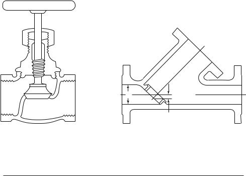
(C.1) Ordinary globe valves as shown in Fig. 122.1.7(C), sketch (a), and other types of valves that have dams or pockets where sediment can collect, shall not be used on blowoff connections.
(C.2) Y-type globe valves as shown in Fig. 122.1.7(C), sketch (b) or angle valves may be used in vertical pipes, or they may be used in horizontal runs of piping provided they are so constructed or installed that the lowest edge of the opening through the seat is at least 25% of the inside diameter below the centerline of the valve.
(C.3) The blowoff valve or valves, the pipe between them, and the boiler connection shall be of the same size except that a larger pipe for the return of condensate may be used.
(C.4) For all boilers [except electric steam boilers having a normal water content not exceeding 100 gal (380 L), traction-purpose, and portable steam boilers; see (C.11) and (C.12) below] with allowable working pressure in excess of 100 psig [690 kPa (gage)], each bottom blowoff pipe shall have two slow-opening
valves, or one quick-opening valve or cock, at the boiler nozzle followed by a slow-opening valve. All valves shall comply with the requirements of (C.5) and (C.6) below.
(C.5) When the value of P required by para. 122.1.4(A.1) does not exceed 250 psig [1 725 kPa (gage)], the valves or cocks shall be bronze, cast iron, ductile iron, or steel. The valves or cocks, if of cast iron, shall not exceed NPS 21⁄2 and shall meet the requirements of the applicable ASME standard for Class 250, as given in Table 126.1, and if of bronze, steel, or ductile iron construction, shall meet the requirements of the applicable standards as given in Table 126.1 or para. 124.6.
(C.6) When the value of P required by para. 122.1.4(A.1) is higher than 250 psig [1 725 kPa (gage)], the valves or cocks shall be of steel construction equal at least to the requirements of Class 300 of the applicable ASME standard listed in Table 126.1. The minimum pressure rating shall be equal to the value of P required by para. 122.1.4(A.1).
(C.7) If a blowoff cock is used, the plug shall be held in place by a guard or gland. The plug shall be distinctly marked in line with the passage.
(C.8) A slow-opening valve is a valve that requires at least five 360 deg turns of the operating mechanism to change from fully closed to fully opened.
(C.9) On a boiler having multiple blowoff pipes, a single master valve may be placed on the common blowoff pipe from the boiler, in which case only one valve on each individual blowoff is required. In such a case, either the master valve or the individual valves or cocks shall be of the slow-opening type.
(C.10) Two independent slow-opening valves, or a slow-opening valve and a quick-opening valve or cock, may be combined in one body and may be used provided the combined fitting is the equivalent of two independent slow-opening valves, or a slow-opening valve and a quick-opening valve or cock, and provided further that the failure of one to operate cannot affect the operation of the other.
(C.11) Only one blowoff valve, which shall be either a slow-opening or quick-opening blowoff valve or a cock, is required on traction and/or portable boilers.
(C.12) Only one blowoff valve, which shall be of a slow-opening type, is required for the blowoff piping for forced circulation and electric steam boilers having a normal water content not exceeding 100 gal (380 L). Electric boilers not exceeding a normal water content of 100 gal (380 L) and a maximum MAWP of 100 psig [690 kPa (gage)] may use a quick-opening manual or slow-opening automatic quarter-turn valve up to NPS 1. Electric boilers not exceeding a normal water content of 100 gal (380 L) but with a MAWP greater than 100 psig [690 kPa (gage)] shall only use either a slow-opening type manual or automatic valve, regardless of size.
--`,,```````,,```,`,`,,,,`,`,`,`-`-`,,`,,`,`,,`--- |
54 |
Copyright ASME International
Provided by IHS under license with ASME
No reproduction or networking permitted without license from IHS
ASME B31.1-2010
Fig. 122.1.7(C) Typical Globe Valves
di |
1/4 di min. |
(a) |
(b) |
Table 122.2 Design Pressure for Blowoff/Blowdown Piping Downstream of BEP Valves
Boiler or Vessel Pressure |
|
Design Pressure [Note (1)] |
|||
MAWP |
|
kPa (gage) |
|
psig |
kPa (gage) |
|
|
|
|
|
|
Below 250 |
|
1 725 |
|
Note (2) |
Note (2) |
250–600 |
1 |
725–4 135 |
250 |
1 725 |
|
601–900 |
4 |
136–6 205 |
400 |
2 760 |
|
901–1,500 |
6 |
206–10 340 |
600 |
4 135 |
|
1,501 and higher |
10 341 and higher |
900 |
6 205 |
||
|
|
|
|
|
|
NOTES:
(1)The allowable stress value for the piping material need not exceed that permitted for the temperature of saturated steam at the design pressure.
(2)For boiler or vessel pressures below 250 psig [1 725 kPa (gage)], the design pressure shall be determined in accordance with para. 122.1.4(B.1), but need not exceed 250 psig [1 725 kPa (gage)].
(D) Safety Valves
(D.1) Safety valves, relief valves, and safety relief valves shall conform to the requirements of PG-67, PG-68, PG-69, PG-70, PG-71, PG-72, and PG-73 of Section I of the ASME Boiler and Pressure Vessel Code.
122.2Blowoff and Blowdown Piping in Nonboiler External Piping
Blowoff and blowdown piping systems shall be, where possible, self-draining and without pockets. If unavoidable, valved drains at low points shall allow system draining prior to operation. In order to minimize pipeline shock during the operation of blowoff systems, 3D pipe bends (minimum) should be used in preference to elbows, and wye or lateral fittings should be used in preference to tee connections.
55
(A) From Boilers
(A.1) Blowoff piping, located between the valves described in para. 122.1.4(A) and the blowoff tank or other point where the pressure is reduced approximately to atmospheric pressure and cannot be increased by closing a downstream valve, shall be designed for the appropriate pressure in accordance with Table 122.2. The provisions of paras. 122.1.4(A.3) and 122.1.7 shall apply. The size of non-BEP blowoff header to the safe point of discharge shall not be smaller than the largest connected BEP blowoff terminal [see para. 122.1.4(A.4)].
(A.2) Blowdown piping, in which the pressure cannot be increased by closing a downstream valve, shall be designed for the appropriate pressure and temperature in accordance with Table 122.2. The provisions of
--`,,```````,,```,`,`,,,,`,`,`,`-`-`,,`,,`,`,,`---
Copyright ASME International
Provided by IHS under license with ASME
No reproduction or networking permitted without license from IHS
ASME B31.1-2010
para. 122.1.4(B.3) shall apply. The size of non-BEP blowdown piping between the shutoff valve described in para. 122.1.4(B) and the flow control valve shall not be smaller than the BEP boiler shutoff valve [see para. 122.1.4(B.4)] unless engineering calculations confirm that the design flow rate can be achieved with a smaller piping size without flashing the blowdown prior to the flow control valve.
(A.3) When the design pressure of Table 122.2 can be exceeded due to closing of a downstream valve, calculated pressure drop, or other means, the entire blowoff or blowdown piping system shall be designed in accordance with paras. 122.1.4(A) and 122.1.7 for blowoff and para. 122.1.4(B) for blowdown piping.
(A.4) Non-BEP blowdown piping downstream of the flow control valve shall not be smaller — and preferably will be larger — than the connection on the boiler [see para. 122.1.4(B.4)].
(B) From Pressure Vessels Other Than Boilers
(B.1) The design pressure and temperature of the blowoff piping from the pressure vessel to and including the blowoff valve(s) shall not be less than the vessel MAWP and corresponding design temperature.
122.3 Instrument, Control, and Sampling Piping
(A) The requirements of this Code, as supplemented by para. 122.3, shall apply to the design of instrument, control, and sampling piping for safe and proper operation of the piping itself.
(B) The term “Instrument Piping” shall apply to all valves, fittings, tubing, and piping used to connect instruments to main piping or to other instruments or apparatus or to measuring equipment as used within the classification of para. 100.1.
(C) The term “Control Piping” shall apply to all valves, fittings, tubing, and piping used to interconnect pneumatically or hydraulically operated control apparatus, also classified in accordance with para. 100.1, as well
as-- |
to signal transmission systems used to interconnect |
`-`,,```````,,```,`,`,,,,`,`,`,` |
(E) Paragraph 122.3 does not apply to tubing used in |
instrument transmitters and receivers. |
|
(D) The term “Sampling Piping” shall apply to all valves, fittings, tubing, and piping used for the collection of samples, such as steam, water, oil, gas, and chemicals.
-
permanently closed systems, such as fluid-filled temper- |
|
ature`,,`,,`,`,,` |
responsive devices, or the temperature responsive |
--- |
|
devices themselves. |
|
(F) Paragraph 122.3 does not apply to the devices, apparatus, measuring, sampling, signalling, transmitting, controlling, receiving, or collecting instruments to which the piping is connected.
122.3.1 Materials and Design. The materials utilized for valves, fittings, tubing, and piping shall meet the particular conditions of service and the requirements of the applicable specifications listed under general paras. 105, 106, 107, and 108 with allowable stresses in
accordance with the Allowable Stress Tables in Appendix A.
The materials for pressure retention components used for piping specialties such as meters, traps, and strainers in flammable, combustible, or toxic fluid systems shall in addition conform to the requirements of paras. 122.7 and 122.8.
122.3.2Instrument Piping
(A)Takeoff Connections
(A.1) Takeoff connections at the source, together with attachment bosses, nozzles, and adapters, shall be made of material at least equivalent to that of the pipe or vessel to which they are attached. The connections shall be designed to withstand the source design pressure and temperature and be capable of withstanding loadings induced by relative displacement and vibration. The nominal size of the takeoff connections shall not be less than NPS 1⁄2 for service conditions not in excess of either 900 psi (6 200 kPa) or 800°F (425°C), and NPS 3⁄4 (for adequate physical strength) for design conditions that exceed either of these limits. Where the size of the main is smaller than the limits given above, the takeoff connection shall not be less than the size of the main line.
(A.2) To prevent thermal shock to the main steam line by contact with the colder condensate return from the instrument, steam meter or instrument takeoff connections shall be lagged in with the steam main. For temperature in excess of 800°F (425°C), they may also be arranged to make metallic contact lengthwise with the steam main.
(B) Valves
(B.1) Shutoff Valves. Shutoff valves shall be provided at takeoff connections. They shall be capable of withstanding the design pressure and temperature of the pipe or vessel to which the takeoff adapters or nipples are attached.
(B.2) Blowdown Valves
(B.2.1) Blowdown valves at or near the instrument shall be of the gradual opening type. For subcritical pressure steam service, the design pressure for blowdown valves shall be not less than the design pressure of the pipe or vessel; the design temperature shall be the corresponding temperature of saturated steam. For all other services, blowdown valves shall meet the requirements of (B.1) above.
(B.2.2) When blowdown valves are used, the valves at the instrument as well as any intervening fittings and tubing between such blowdown valves and the meter shall be suitable at 100°F (40°C) for at least 11⁄2 times the design pressure of the piping system, but the rating of the valve at the instrument need not exceed the rating of the blowdown valve.
(B.2.3) When blowdown valves are not used, instrument valves shall conform to the requirements of (B.2.1) above.
56
Copyright ASME International
Provided by IHS under license with ASME
No reproduction or networking permitted without license from IHS
ASME B31.1-2010
(C) Reservoirs or Condensers. In dead end steam service, the condensing reservoirs and connecting nipples, which immediately follow the shutoff valves, shall be made of material suitable for the saturated steam temperature corresponding to the main line design pressure.
(D) Materials for Lines Between Shutoff Valves and Instruments
(D.1) Copper, copper alloys, and other nonferrous materials may be used in dead end steam or water services up to the design pressure and temperature conditions used for calculating the wall thickness in accordance with para. 104 provided that the temperature within the connecting lines for continuous services does not exceed 406°F (208°C).
Where water temperature in the reservoir of condensers is above 406°F (208°C), a length of uninsulated steel tubing at least 5 ft (1.5 m) long shall immediately follow the condenser ahead of the connecting copper tubing to the instrument.
|
(D.2) The minimum size of the tubing or piping is |
|
a function of its length, the volume of fluid required to |
|
produce full scale deflections of the instrument, and the |
|
service of the instrument. When required to prevent |
-- |
plugging as well as to obtain sufficient mechanical |
-`-`,,```````,,```,`,`,,,,`,`,`,` |
strength, the inside diameter of the pipe or tube should |
|
|
|
not be less than 0.36 in. (9.14 mm), with a wall thickness |
|
of not less than 0.049 in. (1.25 mm). When these require- |
|
ments do not apply, smaller sizes with wall thickness |
---`,,`,,`,`,,` |
in due proportions may be used. In either case, wall |
of (D.3) below. |
|
|
thickness of the pipe or tube shall meet the requirements |
|
(D.3) The piping or tubing shall be designed in |
|
accordance with para. 104 with consideration for water |
|
hammer. |
|
(E) Fittings and Joints |
|
(E.1) For dead end steam service and for water |
|
above 150°F (65°C), fittings of the flared, flareless, or |
|
socket welding type, or other suitable type of similar |
|
design shall be used. The fittings shall be suitable for |
|
the header pressure and corresponding saturated steam |
|
temperature or water temperature, whichever applies. |
|
For supercritical pressure conditions the fittings shall |
|
be suitable for the design pressure and temperature of |
|
the main fluid line. |
|
(E.2) For water, oil and similar instrument services, |
|
any of the following types may be used, within the |
|
pressure–temperature limitations of each: |
|
(E.2.1) For main line hydraulic pressures above |
|
500 psi (3 450 kPa) and temperatures up to 150°F (65°C), |
|
steel fittings either of the flared, flareless, socket welded, |
|
fusion welded, or silver brazed socket type shall be used. |
|
(E.2.2) For main line pressures up to 500 psi |
|
(3 450 kPa) and temperatures up to 150°F (65°C), the |
|
fittings may be flared or silver brazed socket type, |
|
inverted flared or flareless compression type, all of brass |
|
or bronze. |
57
(E.2.3) For pressures up to 175 psi (1 200 kPa) or temperatures up to 250°F (120°C), soldered type fittings may be used with water-filled or air-filled tubing under adjusted pressure–temperature ratings. These fittings are not recommended where mechanical vibration, hydraulic shock, or thermal shock are encountered.
122.3.3Control Piping
(A)Takeoff Connections
(A.1) Takeoff connections shall be in accordance with para. 122.3.2(A.1).
(B) Valves
(B.1) Shutoff valves shall be in accordance with para. 122.3.2(B.1).
(C) Materials
(C.1) The same materials may be used for control lines as for instrument lines, except that the minimum inside diameter shall be 0.178 in. (4.52 mm) with a minimum wall thickness of 0.028 in. (0.71 mm), provided that this wall thickness is not less than that required by para. 122.3.2(D.3). If a control device has a connection smaller than 1⁄4 in. (6.0 mm), the size reduction from the control tubing to the control device shall be made as close to the control device as possible.
(D) Fittings and Joints
(D.1) Fittings and joints shall be in accordance with para. 122.3.2(E.2).
122.3.4Sampling Piping
(A)Takeoff Connections
(A.1) Takeoff connections shall be in accordance with para. 122.3.2(A.1).
(B) Valves
(B.1) Shutoff valves shall be in accordance with para. 122.3.2(B.1).
(B.2) Blowdown valves shall be of the gradual opening type and shall be suitable for main line design pressure and temperature.
(C) Materials
(C.1) The materials to be used for sampling lines shall conform to minimum requirements for the main line to which they connect.
(D) Fittings and Joints
(D.1) For subcritical and supercritical pressure steam, and for water above 150°F (65°C), fittings of the flared, flareless, or socket welding type, or other suitable type of similar design shall be used. The fittings shall be suitable for main line design pressure and temperature.
(D.2) For water below 150°F (65°C), fittings and joints shall be suitable for main line design pressure and temperature and shall be in accordance with para. 122.3.2(E.2).
122.3.6Fittings and Joints
(A)All fittings shall be in accordance with standards and specifications listed in Table 126.1.
(A.1) Socket welded joints shall comply with the requirements of para. 111.3.
Copyright ASME International
Provided by IHS under license with ASME
No reproduction or networking permitted without license from IHS

ASME B31.1-2010
(A.2) Flared, flareless, and compression type fittings and their joints shall comply with the requirements of para. 115.
(A.3) Silver brazed socket type joints shall comply with the requirements of paras. 117.1 and 117.3.
(A.4) Solder type joints shall comply with the requirements of paras. 117.2 and 117.3.
(A.5) The use of taper threaded joints up to and including NPS 1⁄2 is permitted at pressures up to 5,000 psi (34 500 kPa) in dead end service from outlet end and downstream of shutoff valve located at instrument, at control apparatus, or at discharge of sample cooler.
122.3.7Special Safety Provisions
(A)Connecting piping subject to clogging from solids or deposits shall be provided with suitable connections for cleaning.
(B)Connecting piping handling air and gases containing moisture or other extraneous materials shall be provided with suitable drains or settling chambers or traps.
(C)Connecting piping that may contain liquids shall be protected from damage due to freezing by heating or other adequate means.
122.3.8Supports. Supports shall be furnished as specified in para. 121 not only for safety but also to protect the piping against detrimental sagging, external mechanical injury abuse, and exposure to unusual service conditions.
122.3.9Installations
(A)Instrument, control, and sampling piping shall be inspected and tested in accordance with paras. 136 and 137.
(B)The inside of all piping, tubing, valves, and fittings shall be smooth, clean, and free from blisters, loose mill scale, sand, and dirt when erected. All lines shall be cleaned after installation and before placing in service.
122.4Spray-Type Desuperheater Piping for Use on Steam Generators, Main Steam, and Reheat Steam Piping
(A)Valves and Piping Arrangement
(A.1) Each spraywater pipe connected to a desuperheater shall be provided with a stop valve and a regulating (spray control) valve. The regulating valve shall be installed upstream of the stop valve. In addition, if the steam generator supplies steam to a steam turbine, a power-operated block valve5 shall be installed upstream of the regulating valve.
(A.2) A bypass valve around the regulating valve is permitted.
(A.3) A bypass valve around the power-operated block valve is prohibited.
5 For information on the prevention of water damage to steam turbines used for electric power generation, see ASME TDP-1.
(A.4) On a superheater or reheater desuperheater, a drain valve shall be installed between the poweroperated block valve and the regulating valve.
(A.5) If the spraywater supply is from the boiler feedwater system and its source is not downstream of the feedwater check valve required by para. 122.1.7, a check valve shall be provided in the spraywater piping between the desuperheater and the spraywater source.
(A.6) It is recommended that the valves and piping be arranged to provide a head of water on the downstream side of the stop valve.
(A.7) A typical arrangement is shown in Fig. 122.4.
(A.8) Provisions shall be made to both steam and water systems to accommodate the operating conditions associated with this service including: water hammer, thermal shock and direct water impingement. The connection for the spraywater pipe should be located per the requirements established by the manufacturer so that complete flow mixing is achieved prior to any bends, elbows, or other flow directional changes being encountered.
(A.9) Insertable-type desuperheaters, which include an integral stop and spraywater regulating valve, may be used within the limitations established by the manufacturer. If this type is used, the individual stop and regulating valves shown in Fig. 122.4 may be omitted. All other requirements described in para. 122.4 shall apply.
(A.10) For Desuperheaters Located Within Main Steam or Reheat Steam Piping. The steam system to be desuperheated shall be provided with proper drainage during all water flow conditions. The drainage system shall function both manually and automatically.
(B) Design Requirements
(B.1) The value of P to be used in the formulas of para. 104 shall be as follows:
(B.1.1) For piping from the desuperheater back to the stop valve required by (A.1) above, the value of P shall be equal to or greater than the maximum allowable working pressure of the desuperheater.
(B.1.2) For the remainder of the spraywater piping system, the value of P shall be not less than the maximum sustained pressure exerted by the spraywater.
(B.2) The stop valve required by (A.1) above shall be designed for the pressure requirement of (B.1.1) above or the maximum sustained pressure exerted by the spraywater, whichever is greater.
(B.3) The S value used for the spraywater piping shall not exceed that permitted for the expected temperature.
NOTE: The temperature varies from that of the desuperheater to that of the spraywater source and is highly dependent on the piping arrangement. It is the responsibility of the designer to determine the design temperature to be used for the various sections of the piping system.
58
--`,,```````,,```,`,`,,,,`,`,`,`-`-`,,`,,`,`,,`---
Copyright ASME International
Provided by IHS under license with ASME
No reproduction or networking permitted without license from IHS
ASME B31.1-2010
Fig. 122.4 Desuperheater Schematic Arrangement
Desuperheater
Stop valve
From spray water source
Regulating valve
Block valve
Drain valve — required on superheater and reheater desuperheaters
GENERAL NOTE: This Figure is a schematic only and is not intended to show equipment layout or orientation.
122.5Pressure-Reducing Valves
122.5.1General. Where pressure-reducing valves are used, one or more relief devices or safety valves shall be provided on the low pressure side of the system. Otherwise, the piping and equipment on the low pressure side of the system shall be designed to withstand the upstream design pressure. The relief or safety devices shall be located adjoining or as close as practicable to the reducing valve. The combined relieving capacity provided shall be such that the design pressure of the low pressure system will not be exceeded if the reducing valve fails open.
122.5.2Bypass Valves. Hand controlled bypass valves having a capacity no greater than the reducing valve may be installed around pressure reducing valves if the downstream piping is protected by relief valves as required in para. 122.5.1 or if the design pressure of the downstream piping system and equipment is at least as high as the upstream pressure.
122.5.3Design of Valves and Relief Devices. Pressure reducing and bypass valves, and relief devices, shall be designed for inlet pressure and temperature conditions. Safety and relief valves shall be in accordance with the requirements of para. 107.8 of this Code.
122.6 Pressure Relief Piping
Pressure relief piping within the scope of this Code shall be supported to sustain reaction forces, and shall
59
--`,,```````,,```,`,`,,,,`,`,`,`-`-`,,`,,`,`,,`---
conform to the requirements of paras. 122.6.1 and 122.6.2.
122.6.1Piping to Pressure-Relieving Safety Devices
(A)There shall be no intervening stop valve(s) between piping being protected and the protective device(s).
(B)Diverter or changeover valves designed to allow servicing of redundant protective devices without system depressurization may be installed between the piping to be protected and the required protective devices under the following conditions:
(B.1) Diverter or changeover valves are prohibited on boiler external piping or reheat piping.
(B.2) One hundred percent (100%) of the required relieving capacity shall be continuously available any time the system is in service.
(B.3) Positive position indicators shall be provided on diverter or changeover valves.
(B.4) Positive locking mechanisms and seals shall be provided on diverter or changeover valves to preclude unauthorized or accidental operation.
(B.5) Diverter or changeover valves shall be designed for the most severe conditions of pressure, temperature, and loading to which they are exposed, and shall be in accordance with para. 107.
(B.6) Provision shall be made to safely bleed off the pressure between the isolated protective device and the diverter or changeover valve.
Copyright ASME International
Provided by IHS under license with ASME
No reproduction or networking permitted without license from IHS
ASME B31.1-2010
122.6.2 Discharge Piping From Pressure-Relieving
Safety Devices
(A)There shall be no intervening stop valve between the protective device or devices and the point of discharge.
(B)When discharging directly to the atmosphere, discharge shall not impinge on other piping or equipment and shall be directed away from platforms and other areas used by personnel.
(C)It is recommended that individual discharge lines be used, but if two or more reliefs are combined, the discharge piping shall be designed with sufficient flow area to prevent blowout of steam or other fluids. Sectional areas of a discharge pipe shall not be less than the full area of the valve outlets discharging thereinto and the discharge pipe shall be as short and straight as possible and so arranged as to avoid undue stresses on the valve or valves.
(D)Discharge lines from pressure-relieving safety devices within the scope of this Code shall be designed to facilitate drainage.
(E)When the umbrella or drip pan type of connection is used, the discharge piping shall be so designed as to prevent binding due to expansion movements.
(F)Drainage shall be provided to remove water collected above the safety valve seat.
(G)Carbon steel materials listed in Appendix A may be used for discharge piping that is subjected to temperatures above 800°F (427°C) only during operation of pressure relieving safety devices provided that
(G.1) the duration of pressure relieving safety device operation is self-limiting
(G.2) the piping discharges directly to atmosphere
(G.3) the allowable stresses for carbon steel materials at temperatures above 800°F (427°C) shall be taken from Section II, Part D, Table 1A for materials applicable to Section I and Section VIII, Division 1 of the ASME Boiler and Pressure Vessel Code
122.7Piping for Flammable or Combustible Liquids
122.7.1General. Piping for flammable or combustible liquids including fuel and lubricating oils is within the scope of this Code. Piping for synthetic lubricants having no flash or fire point need not meet the requirements of para. 122.7.
The designer is cautioned that, among other criteria, static electricity may be generated by the flowing fluid. Additionally, the designer is cautioned of the extreme chilling effect of a liquefied gas flashing to vapor during loss of pressure. This is a factor for determining the lowest expected service temperature relative to the possibility of brittle fracture of materials. Consideration
shall also be given to the pressure rise that may occur as a cold fluid absorbs heat from the surroundings.
122.7.2Materials
(A)Seamless steel or nickel alloy piping materials shall be used in all areas where the line is within 25 ft (7.6 m) of equipment or other lines having an open flame or exposed parts with an operating temperature above 400°F (204°C). Seamless steel or nickel alloy pipe shall also be used for fuel oil systems located downstream of burner shutoff valve(s). The burner shutoff valve(s) shall be located as close to the burner as is practical.
(B)In all other areas, piping systems may include pipe or tube of steel, nickel alloy, copper, or brass construction. Copper tubing shall have a thickness not less than that required by para. 104.1.2(C.3), regardless of pressure. Refer also to paras. 105, 124.6, and 124.7(A).
Wherever materials other than steel or nickel alloy are used, they shall be so located that any spill resulting from the failure of these materials will not unduly expose persons, buildings, or structures, or can be readily controlled by remote valves.
(C)For lubricating oil systems, steel tubing is an acceptable alternative to steel pipe.
(D)Polyethylene (PE) and reinforced thermosetting resin (RTR) pipe may be used for flammable or combustible liquids in buried installations only. The fluid temperatures shall not exceed 140°F (60°C) and pressures shall be limited to 150 psi (1 000 kPa). Where such PE or RTR pipe is used in flammable or combustible liquid service, the rules of Appendix III shall be considered mandatory. Where jurisdictional requirements mandate that double containment pipe be used, the rules of Appendix III shall be applied to both the inner and outer pipe.
Particular care must be exercised to prevent damage to RTR piping at the connection to the main or other facility. Precautions shall be taken to prevent crushing or shearing of RTR piping due to external loading or settling of backfill and to prevent damage or pull out from the terminal connection resulting from thermal expansion or contraction.
RTR piping may terminate above ground and outside a building, provided that:
(D.1) the above ground portion of the RTR pipe is completely enclosed in a conduit or casing of sufficient strength to provide protection from external damage and deterioration. Where a flexible conduit is used, the top of the riser must be attached to a solid support. The conduit or casing shall extend a minimum of 6 in. (150 mm) below grade.
(D.2) the RTR pipe is not subjected to excessive stresses due to external loading.
122.7.3Piping Joints
(A)Welded joints shall be used between steel or nickel alloy piping components where practicable. Where bolted flanged joints are necessary, the gasket material
60
--`,,```````,,```,`,`,,,,`,`,`,`-`-`,,`,,`,`,,`---
Copyright ASME International
Provided by IHS under license with ASME
No reproduction or networking permitted without license from IHS
ASME B31.1-2010
shall be suitable for the service. Where threaded joints and compression fittings are unavoidable, the following requirements shall be met:
(A.1) For threaded joints, the pipe thickness shall be not less than Extra Strong regardless of pressure or type of material.
(A.2) The requirements of para. 114 shall apply to all threaded joints.
(A.3) Threaded joints and compression fittings shall be assembled carefully to ensure leak tightness. Threaded joints shall meet the requirements of para. 135.5. Compression fittings shall meet the requirements of paras. 115 and 135.6. A thread sealant, suitable for the service, shall be used in threaded joints unless the joint is to be seal welded or a gasket or O-ring is used to provide sealing at a surface other than the threads.
(B)Threaded joints in copper or brass pipe shall be subject to the same limitations as for steel pipe in (A.1), (A.2), and (A.3), above.
(C)Copper tubing shall be assembled with flared, flareless, or compression type joints as prescribed in para. 115, or brazed in accordance with para. 117. Soft solder type joints are prohibited.
(D)RTR pipe shall be adhesive bonded in accordance with the pipe manufacturer’s recommended procedures.
(E)Pipe joints dependent on the friction characteristics or resiliency of combustible materials for mechanical or leak tightness of piping shall not be used inside buildings.
(F)Steel tubing shall be assembled with fittings in accordance with para. 115, or with socket weld fittings.
122.7.4Valves and Specialties. Valves, strainers, meters, and other specialties shall be of steel or nickel alloy construction. As an alternative, ductile or malleable iron or copper alloy valves and specialties may be used, subject to the restrictions in paras. 124.6 and 124.7, where metal temperatures do not exceed 400°F (204°C).
122.8Piping for Flammable Gases, Toxic Fluids (Gases or Liquids), or Nonflammable Nontoxic Gases
(A)Although some gases are liquefied for storage or transport, they shall be considered as gases if their Reid vapor pressure is greater than 40 psia [2 068.6 mm Hg (absolute)] at 100°F (37.8°C).
(B)Threaded joints and compression fittings may be used subject to the limitations of para. 114.2.1(B) and other specific limitations identified below, except they are permitted at connections to refillable storage containers and associated pressure regulators, shutoff valves, pumps, and meters, to a maximum pressure of 5,000 psig
[34 475 kPa (gage)], provided the size does not exceed NPS 3⁄4 (DN 20).
122.8.1Flammable Gas
(A)Some of the common flammable gases are acetylene, ethane, ethylene, hydrogen, methane, propane,
butane, and natural or manufactured gas used for fuel. It shall be the designers’ responsibility to determine the limiting concentrations (upper and lower explosive limits) and the properties of the gas under consideration. The use of explosive concentrations shall be avoided, or the piping shall be designed to withstand explosive forces.
The designer is further cautioned of the extreme chilling effect of gas during rapid expansion. This is a factor for determining the lowest expected service temperature relative to the possibility of brittle fracture of materials.
(B) Materials. Steel piping, subject to the limitations in para. 105, shall be used for all flammable gases, except as otherwise permitted in (B.2), (B.3), and (B.4) below.
(B.1) Welded joints shall be used between steel components where practicable. Where bolted flanged joints are necessary, the gasket material shall be suitable for the service. Where threaded joints and compression fittings are unavoidable, the following requirements shall be met:
(B.1.1) For threaded joints, the pipe thickness shall be not less than Extra Strong regardless of pressure or type of material.
(B.1.2) Threaded joints and compression fittings may be used subject to the limitations of para. 122.8(B).
(B.1.3) Threaded joints and compression fittings shall be assembled carefully to ensure leak tightness. Threaded joints shall meet the requirements of para. 135.5. Compression fittings shall meet the requirements of paras. 115 and 135.6. A thread sealant, suitable for the service, shall be used in threaded joints unless the joint is to be seal welded or a gasket or O-ring is used to provide sealing at a surface other than the threads.
(B.2) For hydrogen systems, the following alternative materials may be used:
(B.2.1) seamless steel tubing with welded joints; (B.2.2) seamless copper or brass pipe or tubing with brazed, threaded, or compression fitting joints.
Threaded fittings shall not exceed NPS 3⁄4 (DN 20). For protection against damage, tubing shall be installed in a guarded manner that will prevent damage during construction, operation, or service. Valves with suitable packing, gages, regulators, and other equipment may also consist of copper alloy materials. Safety relief devices shall be vented individually, and connected vent piping shall be designed to convey the fluid, without pockets, to the outside atmosphere; and then directed away from equipment ventilation systems, and vents from other systems.
(B.3) For fuel gas instrumentation and control, seamless copper tubing subject to the following restrictions may be used:
(B.3.1) The design pressure shall not exceed 100 psi (690 kPa).
(B.3.2) Tubing shall not exceed 5⁄8 in. (15.9 mm) nominal outside diameter.
--61`,,```````,,```,`,`,,,,`,`,`,`-`-`,,`,,`,`,,`---
Copyright ASME International
Provided by IHS under license with ASME
No reproduction or networking permitted without license from IHS

ASME B31.1-2010
(B.3.3) All joints shall be made with compression or flared fittings.
(B.3.4) Copper tubing shall not be used if the fuel gas contains more than 0.3 grains (19.4 mg) of hydrogen sulfide per 100 ft3/min (47 liters/sec) of gas at standard conditions.
(B.3.5) Consideration shall be given in the design to the lower strength and melting point of copper compared to steel. Adequate support and protection from high ambient temperatures and vibration shall be provided.
(B.3.6) Tubing shall be installed in a guarded manner that will prevent damage during construction, operation, and service.
(B.4) Polyethylene (PE) pipe may be used for natural gas service in buried installations only. The fluid temperatures shall not exceed 140°F (60°C) nor be below −20°F (−30°C), and pressures shall be limited to 100 psi (690 kPa). Pipe joints shall be heat fused in accordance with manufacturer’s recommended procedures. Where PE pipe is used in flammable gas service, the rules of Appendix III shall be considered mandatory.
(C)Valves and Specialties. Valves, strainers, meters, and other specialties shall be of steel or nickel alloy construction. As as alternative, ductile iron or copper alloy valves and specialties may be used, subject to the restrictions in paras. 124.6 and 124.7, where metal temperatures do not exceed 400°F (204°C).
(D)For in-plant fuel gas distribution system(s) where the use of a full-relieving-capacity relief valve(s) as described in para. 122.5 could create an undue venting hazard, an alternative pressure limiting design may be substituted. The alternative design shall include all provisions below:
(D.1) Tandem Gas Pressure Reducing Valves. To protect the low pressure system, two gas pressure reducing valves capable of independent operation shall be installed in series. Each shall have the capability of closing off against the maximum upstream pressure, and of controlling the pressure on the low pressure side at or below the design pressure of the low pressure system, in the event that the other valve fails open. Control lines must be suitably protected, designed, and installed so that damage to any one control line will not result in over pressurizing the downstream piping.
(D.2) Trip Stop Valve. A fail-safe trip stop valve shall be installed to automatically close, in less than 1 sec, at or below the design pressure of the downstream piping. It shall be a manually reset design. The pressure switch for initiating closure of the trip stop valve shall be hardwired directly to the valve tripping circuit. The pressure switch shall be mounted directly on the low pressure
-- |
|
-`-`,,```````,,```,`,`,,,,`,`,`,` |
|
piping without an intervening isolation valve. The trip |
|
stop valve shall be located so that it is accessible and |
|
protected from mechanical damage and from weather |
|
or other ambient conditions that could impair its proper |
|
`,,`,,`,`,,` |
62 |
|
|
Copyright ASME International |
|
--- |
|
Provided by IHS under license with ASME |
|
No reproduction or networking permitted without license from IHS
Table 122.8.2(B) Minimum Wall Thickness
Requirements for Toxic Fluid Piping
|
Carbon and Low |
Stainless and |
|
Alloy Steel |
Nickel Alloy Steel |
|
(Appendix A, |
(Appendix A, |
|
Tables |
Tables |
|
A-1 and A-2) |
A-3 and A-4) |
|
|
|
NPS 2 (DN 50) and |
Extra strong |
Schedule 10S |
smaller |
|
|
Larger than NPS 2 |
Standard weight |
Schedule 5S |
(DN 50) |
|
|
|
|
|
functioning. It may be located upstream or downstream of the tandem gas pressure reducing valves. The trip stop valve and all upstream piping shall be designed for the maximum upstream supply pressure. The trip stop valve may also serve as the upstream isolation valve of a double-block and vent gas supply isolation system. Provision shall be made to safely bleed off the pressure downstream of the trip stop valve.
(D.3) Safety Relief Device. The low pressure system shall be protected from any leakage through the pressure reducing valves, when closed, by a safety relief device(s) constructed and designed in accordance with paras. 107.8.3 and 122.5.3, and sized for the possible leakage rate.
122.8.2Toxic Fluids (Gas or Liquid)
(A)For the purpose of this Code, a toxic fluid is one that may be lethal, or capable of producing injury and/ or serious illness through contact, inhalation, ingestion, or absorption through any body surface. It shall be the designers’ responsibility to adopt the safety precautions published by the relevant fluid industry which may be more stringent than those described in this Code for toxic fluids. In addition, the piping shall be installed in such a manner that will minimize the possibility of damage from external sources.
(B)Preferably, pipe and pipe fittings should be seamless steel. Wall thickness shall not be less than that in Table 122.8.2(B).
If the fluid is known to be corrosive to the steels in Table 122.8.2(B), the materials and wall thickness selected shall be suitable for the service. (Refer to para. 104.1.2.)
(C)Welded joints shall be used between steel components where practicable. Backing rings used for making girth butt welds shall be removed after welding. Miter welds are prohibited. Fabricated branch connections (shaped branch pipe welded directly to run pipe) may be used only if other types of branch connections permitted by para. 104.3.1 are not available. Socket welded
joints shall be used only with steel materials and shall not be larger than NPS 21⁄2 (DN 65). Where bolted flanged joints are necessary, socket weld or welding neck flanges
ASME B31.1-2010
shall be used. Gasket materials shall be suitable for the service. Compression fittings are prohibited. Where the use of threaded joints is unavoidable, all of the following requirements shall be met:
(C.1) The pipe thickness shall be not less than Extra Strong, regardless of pressure or type of material.
(C.2) In addition to the provisions of para. 122.8(B), threaded joints and compression fittings may be used at connections to refillable storage containers and associated pressure regulators, shutoff valves, pumps, and meters to a maximum pressure of 50 psig [345 kPa (gage)], provided the size does not exceed NPS 2 (DN 50).
(C.3) Threaded joints shall be assembled carefully to ensure leak tightness. The requirements of para. 135.5 shall be met. A thread sealant, suitable for the service, shall be used unless the joint is to be seal welded or a gasket or O-ring is used to provide sealing at a surface other than the threads.
(D)Steel valves shall be used. Bonnet joints with tapered threads are not permitted. Special consideration shall be given to valve design to prevent stem leakage to the environment. Bonnet or cover plate closures and other body joints shall be one of the following types:
(D.1) union
(D.2) flanged with suitable gasketing and secured by at least four bolts
(D.3) proprietary, attached by bolts, lugs, or other substantial means, and having a design that increases gasket compression as fluid pressure increases
(D.4) threaded with straight threads sufficient for mechanical strength, metal-to-metal seats, and a seal weld made in accordance with para. 127.4.5, all acting in series
(E)Tubing not larger than 5⁄8 in. (16 mm) O.D. with socket welding fittings may be used to connect instruments to the process line. An accessible root valve shall be provided at the process lines to permit isolating the tubing from the process piping. The layout and mounting of tubing shall minimize vibration and exposure to possible damage.
(F)The provisions of para. 102.2.4 are not permitted. The simplified rules for analysis in para. 119.7.1 (A.3) are not permitted. The piping system shall be designed to minimize impact and shock loads. Suitable dynamic analysis shall be made where necessary to avoid or minimize vibration, pulsation, or resonance effects in the piping. The designer is cautioned to consider the possibility of brittle fracture of the steel material selected over the entire range of temperatures to which it may be subjected.
(G)For dry chlorine service between −29°C (−20°F) and 149°C (300°F), the pipe material shall not be less in thickness than seamless Extra Strong steel.
(H)Toxic fluid piping shall be pneumatic leak tested in accordance with para. 137.5. Alternatively, mass spectrometer or halide leak testing in accordance with
para. 137.6, and a hydrostatic test in accordance with para. 137.3 may be performed.
122.8.3Nonflammable Nontoxic Gas
(A)Piping for nonflammable and nontoxic gases, such as air, oxygen, carbon dioxide, and nitrogen, shall comply with the requirements of this Code, except as otherwise permitted in (B) (below). The designer is cautioned of the extreme chilling effect during rapid expansion. This is a factor for determining the lowest expected service temperature relative to the brittle fracture of the material selected.
(B)Threaded joints and compression fittings may be used subject to the conditions of para. 122.8(B).
122.9Piping for Corrosive Liquids and Gases
Where it is necessary to use special material, such as glass, plastics, or metallic piping lined with nonmetals, not listed in Table 126.1, for conveying corrosive or hazardous liquids and gases, the design shall meet the requirements of para. 104.7.
122.10 Temporary Piping Systems
Prior to test and operation of the power plant and its included piping systems, most power and auxiliary service piping are subjected to flushing or chemical cleaning to remove internal foreign material such as rust particles, scale, welding or brazing residue, dirt, etc., which may have accumulated within the piping during the construction period. The flushing or cleaning operation may be accomplished by blowing out with steam or air, by hot oil circulation of oil systems, by acid or caustic fluid circulation, or by other flushing or cleaning methods. Temporary piping, that is piping attached to the permanent piping system whose function is to provide means for introducing and removing the fluids used in the flushing or cleaning operations, shall be designed and constructed to withstand the operating conditions during flushing and cleaning. The following minimum requirements shall apply to temporary piping systems:
(A)Each such system shall be analyzed for compliance with para. 103.
(B)Connections for temporary piping to the permanent piping systems that are intended to remain, shall meet the design and construction requirements of the permanent system to which they are attached.
(C)The temporary systems shall be supported such that forces and moments due to static, dynamic and expansion loadings will not be transferred in an unacceptable manner to the connected permanent piping system. Paragraphs 120 and 121 shall be used as guidance for the design of the temporary piping systems supporting elements.
(D)The temporary systems shall be capable of withstanding the cyclic loadings that occur during the flushing and cleaning operations. Particular attention shall be given to the effects of large thrust forces that may be
--`,,```````,,```,`,`,,,,`,`,`,`-`-`,,`,,`,`,,`--- |
63 |
Copyright ASME International
Provided by IHS under license with ASME
No reproduction or networking permitted without license from IHS
ASME B31.1-2010
generated during high velocity blowing cycles. Where steam piping is to be subjected to high velocity blowing operations, continuous or automatic draining of trapped or potentially trapped water within the system shall be incorporated. Supports at the exhaust terminals of blowdown piping shall provide for restraint of potential pipe whip.
(E)Where necessary, temporary systems containing cast iron or carbon steel material subject to chemical cleaning shall be prewarmed to avoid the potential for brittle failure of the material.
(F)Where temporary piping has been installed and it does not comply with the requirements of this Code for permanent piping systems, it shall be physically removed or separated from the permanent piping to which it is attached prior to testing of the permanent piping system and prior to plant startup.
122.11Steam Trap Piping
122.11.1Drip Lines. Drip lines from piping or equipment operating at different pressures shall not be connected to discharge through the same trap.
122.11.2Discharge Piping. Trap discharge piping shall be designed to the same pressure as the inlet piping unless the discharge is vented to atmosphere, or is operated under low pressure and has no stop valves. In no case shall the design pressure of trap discharge piping be less than the maximum discharge pressure to which it may be subjected. Where two or more traps discharge into the same header, a stop valve shall be provided in the discharge line from each trap. Where the pressure in the discharge piping can exceed the pressure in the inlet piping, a check valve shall be provided in the trap discharge line. A check valve is not required if either the stop valve or the steam trap is designed to automatically prevent reverse flow and is capable of withstanding a reverse differential pressure equal to the design pressure of the discharge piping.
122.12Exhaust and Pump Suction Piping
Exhaust and pump suction lines for any service and pressure shall have relief valves of suitable size unless the lines and attached equipment are designed for the maximum pressure to which they may accidentally or otherwise be subjected, or unless a suitable alarm indicator, such as a whistle or free blowing relief valve, is installed where it will warn the operator.
122.13 Pump Discharge Piping
Pump discharge piping from the pump up to and including the valve normally used for isolation or flow control shall be designed for the maximum sustained
pressure exerted by the pump and for the highest coincident fluid temperature, as a minimum. Variations in pressure and temperature due to occasional inadvertent operation are permitted as limited in para. 102.2.4 under any of the following conditions:
(A)during operation of overpressure relief devices designed to protect the piping system and the attached equipment
(B)during a short period of abnormal operation, such as pump overspeed
(C)during uncontrolled transients of pressure or temperature
122.14District Heating and Steam Distribution Systems
122.14.1General. Where pressure reducing valves are used, one or more relief devices or safety valves shall be provided on the low pressure side of the system. Otherwise, the piping and equipment on the low pressure side of the system shall be designed to withstand the upstream design pressure. The relief or safety devices shall be located adjoining or as close as practicable to the reducing valve. The combined relieving capacity provided shall be such that the design pressure of the low pressure system will not be exceeded if the reducing valve fails open.
122.14.2Alternative Systems. In district heating and steam distribution systems where the steam pressure does not exceed 400 psi (2 750 kPa) and where the use of relief valves as described in para. 122.14.1 is not feasible (e.g., because there is no acceptable discharge location for the vent piping), alternative designs may be substituted for the relief devices. In either case, it is recommended that alarms be provided that will reliably warn the operator of failure of any pressure reducing valve.
(A)Tandem Steam Pressure Reducing Valves. Two or more steam pressure reducing valves capable of independent operation may be installed in series, each set at or below the safe working pressure of the equipment and piping system served. In this case, no relief device is required.
Each pressure reducing valve shall have the capability of closing off against full line pressure, and of controlling the reduced pressure at or below the design pressure of the low pressure system, in the event that the other valve fails open.
(B)Trip Stop Valves. A trip stop steam valve set to close at or below the design pressure of the low pressure system may be used in place of a second reducing valve or a relief valve.
64
--`,,```````,,```,`,`,,,,`,`,`,`-`-`,,`,,`,`,,`---
Copyright ASME International
Provided by IHS under license with ASME
No reproduction or networking permitted without license from IHS