

ASME B31.1-2010
(10) |
|
|
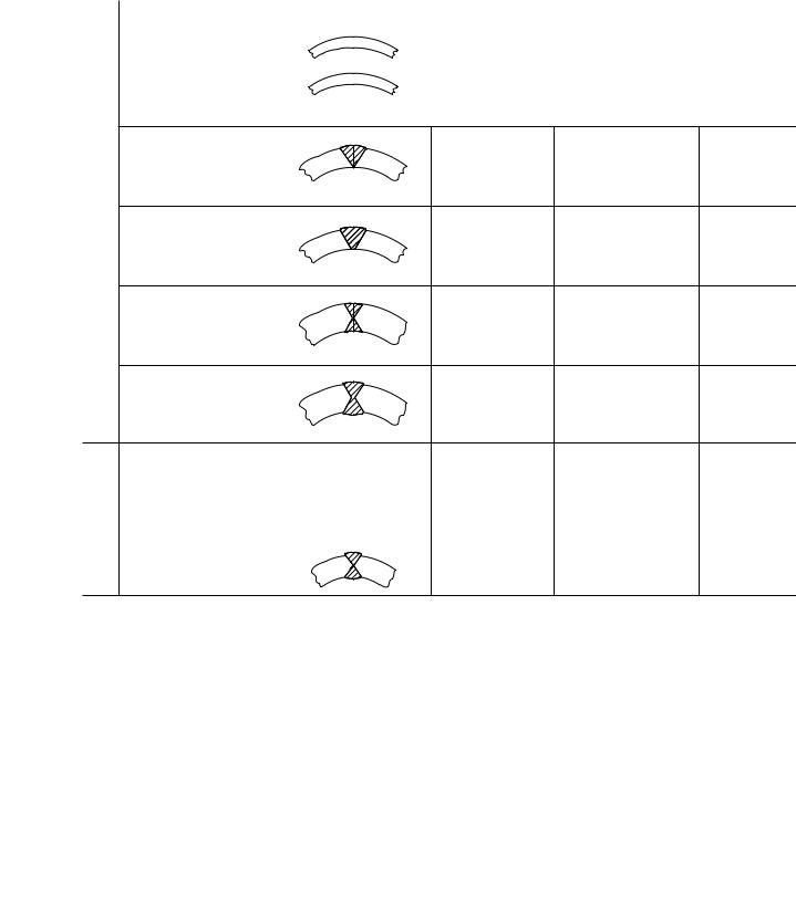
Table 102.4.3 |
Longitudinal Weld Joint Efficiency Factors |
|
||
|
|
|
|
|
|
|
|
|
|
No. |
Type of Joint |
|
Type of Seam |
Examination |
Factor E |
|
|
|
|
|
|
|
|
1 |
Furnace butt weld, con- |
|
Straight |
As required by listed |
0.60 |
||
|
|||||||
|
|
|
tinuous weld |
|
|
specification |
[Note (1)] |
|
|
|
|
|
|
|
|
2 |
Electric resistance weld |
|
Straight or spiral |
As required by listed |
0.85 |
||
|
|||||||
|
|
|
|
|
|
specification |
[Note (1)] |
|
|
|
|
|
|
|
|
3Electric fusion weld
|
(a) Single butt weld |
|
Straight or spiral |
As required by listed |
0.85 |
|
(without filler metal) |
|
|
specification |
|
|
|
|
|
Additionally 100% |
1.00 |
|
|
|
|
RT or UT |
[Note (2)] |
|
(b) Single butt weld |
|
Straight or spiral |
As required by listed |
0.80 |
|
(with filler metal) |
|
|
specification |
|
|
|
|
|
Additionally 100% |
1.00 |
|
|
|
|
RT or UT |
[Note (2)] |
|
(c) Double butt weld |
|
Straight or spiral |
As required by listed |
0.90 |
|
(without filler metal) |
|
|
specification |
|
|
|
|
|
Additionally 100% |
1.00 |
|
|
|
|
RT or UT |
[Note (2)] |
|
(d) Double butt weld |
|
Straight or spiral |
As required by listed |
0.90 |
|
(with filler metal) |
|
|
specification |
|
|
|
|
|
Additionally 100% |
1.00 |
|
|
|
|
RT or UT |
[Note (2)] |
4 |
API 5L |
Submerged arc weld |
Straight with |
As required by speci- |
0.90 |
|
|
(SAW) |
one or two |
fication |
|
|
|
Gas metal arc weld |
seams |
Additionally 100% |
1.00 |
|
|
|
|||
|
|
(GMAW) |
Spiral |
RT or UT |
[Note (2)] |
|
|
Combined GMAW, SAW |
|
|
|
NOTES:
(1)It is not permitted to increase the longitudinal weld joint efficiency factor by additional examination for joint 1 or 2.
(2)RT (radiographic examination) shall be in accordance with the requirements of para. 136.4.5 or the material specification, as applicable. UT (ultrasonic examination) shall be in accordance with the requirements of para. 136.4.6 or the material specification, as applicable.
16
--`,,```````,,```,`,`,,,,`,`,`,`-`-`,,`,,`,`,,`---
Copyright ASME International |
|
Provided by IHS under license with ASME |
|
No reproduction or networking permitted without license from IHS |
Not for Resale, 03/08/2011 00:55:16 MST |
ASME B31.1-2010
Table 102.4.5 Bend Thinning Allowance
|
Minimum Thickness |
|
Recommended Prior to |
Radius of Bends |
Bending |
|
|
6 pipe diameters or greater |
1.06tm |
5 pipe diameters |
1.08tm |
4 pipe diameters |
1.14tm |
3 pipe diameters |
1.25tm |
GENERAL NOTES:
(a)Interpolation is permissible for bending to intermediate radii.
(b)tm is determined by eq. (7) or (8) of para. 104.1.2(A).
(c)Pipe diameter is the nominal diameter as tabulated in ASME B36.10M, Tables 1, and ASME B36.19M, Table 1. For piping with a diameter not listed in these Tables, and also for tubing, the nominal diameter corresponds with the outside diameter.
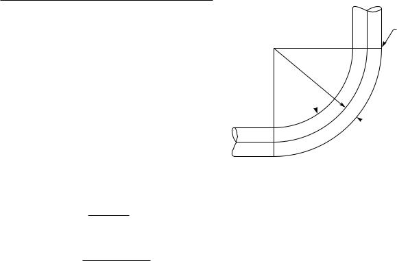
Fig. 102.4.5 Nomenclature for Pipe Bends
End of bend (typ.)
R
Intrados
 Extrados
(B) The minimum required thickness, tm, of a bend, after bending, in its finished form, shall be determined in accordance with eq. (3) or (4)
PDo |
|
|
tm p 2(SE/I + Py) |
+ A |
(3) |
or
Pd + 2SEA/I + 2yPA |
|
tm p 2(SE/I + Py − P) |
(4) |
where at the intrados (inside of bend)
4(R/Do) − 1 |
|
||
I p |
|
|
(5) |
4(R/Do) − 2 |
|||
and at the extrados (outside of bend) |
|
||
4(R/Do) + 1 |
|
||
I p |
|
|
(6) |
4(R/Do) + 2 |
|||
and at the sidewall on the bend centerline, I p1.0 where R p bend radius of pipe bend
Thickness variations from the intrados to the extrados and at the ends of the bend shall be gradual. The thickness requirements apply at the center of the bend arc, at the intrados, extrados, and bend centerline (see Fig. 102.4.5). The minimum thickness at the ends of the bends shall not be less than the requirements of para. 104.1.2 for straight pipe. For bends to conform to this paragraph, all thickness requirements must be met.
102.4.6Casting Quality Factors
(A)General. The use of a casting quality factor is required for all cast components that use the allowable stress values of Appendix A as the design basis. A factor of 0.80 is included in the allowable stress values for all castings given in Appendix A.
This required factor does not apply to component standards listed in Table 126.1, if such standards define allowable pressure–temperature ratings or provide the
17
allowable stresses to be used as the design basis for the component.
(B) For steel materials, a casting quality factor not exceeding 1.0 may be applied when the following requirements are met:
(B.1) All steel castings having a nominal body thickness of 41⁄2 in. (114 mm) or less (other than pipe flanges, flanged valves and fittings, and butt welding end valves, all complying with ASME B16.5 or B16.34) shall be inspected visually (MSS SP-55 may be used for guidance) as follows:
(B.1.1) All critical areas, including the junctions of all gates, risers, and abrupt changes in section or direction and area of weld end preparation shall be radiographed in accordance with Article 2 of Section V of the ASME Boiler and Pressure Vessel Code. The radiographs shall conform to the requirements of ASTM E 446, Reference Radiographs for Steel Castings up to 2 in. (50 mm) in Thickness or ASTM E 186 Reference Radiographs for Heavy Walled (2 to 41⁄2 in. [50 to 114 mm]) Steel Castings, depending upon the section thickness. MSS SP-54 may be used for guidance. The maximum acceptable severity level for a 1.0 quality factor shall be as listed in Table 102.4.6(B.1.1). Where appropriate, radiographic examination (RT) of castings may be supplemented or replaced with ultrasonic examination (UT), provided it is performed in accordance with MSS SP-94.
(B.1.2) All surfaces of each casting, including machined gasket seating surfaces, shall be examined by the magnetic particle or dye penetrant method after heat treatment. The examination techniques shall be in accordance with Article 6 or 7, as applicable, and Article 9 of Section V of the ASME Boiler and Pressure Vessel Code. MSS SP-53 and SP-93 may be used for guidance. Magnetic particle or dye penetrant indications exceeding degree 1 of Type I, degree 2 of Type II, and degree 3 of Type III, and exceeding degree 1 of Types IV
--`,,```````,,```,`,`,,,,`,`,`,`-`-`,,`,,`,`,,`---
(10)
Copyright ASME International
Provided by IHS under license with ASME
No reproduction or networking permitted without license from IHS

ASME B31.1-2010
Table 102.4.6(B.1.1) Maximum Severity Level for Casting Thickness 41⁄2 in. (114 mm) or Less
|
Severity Level |
|
|
||
|
|
|
|
|
|
Discontinuity |
≤1 in. (25 mm) |
>1 in. (25 mm) |
Discontinuity |
|
|
Category Designation |
Thick |
Thick |
Category Designation |
Severity Level |
|
|
|
|
|
|
|
For E 446 [Castings up to 2 in. (50 mm) Thickness] |
|
|
For E 186 [Castings 2 in. to |
|
|
|
|
|
|
41⁄2 in. (50 mm to 114 mm) |
|
|
|
|
|
Thickness] |
|
A |
1 |
2 |
|
|
|
|
|
|
|
A, B, and Types 1 and 2 of C |
2 |
B |
2 |
3 |
|
|
|
|
|
|
|
Type 3 of C |
3 |
C Types 1, 2, |
1 |
3 |
|
|
|
3, and 4 |
|
|
|
|
|
|
|
|
|
D, E, and F |
None |
D, E, F, and G |
None |
None |
|
acceptable |
|
|
acceptable |
acceptable |
|
|
|
|
|
|
|
|
|
and V of ASTM E 125, Standard Reference Photographs for Magnetic Particle Indications on Ferrous Castings, are not acceptable and shall be removed.
(B.1.3) Where more than one casting of a particular design is produced, each of the first five castings shall be inspected as above. Where more than five castings are being produced, the examination shall be performed on the first five plus one additional casting to represent each five additional castings. If this additional casting proves to be unacceptable, each of the remaining castings in the group shall be inspected.
(B.1.4) Any discontinuities in excess of the maximum permitted in (B.1.1) and (B.1.2) above shall be removed, and the casting may be repaired by welding after the base metal has been inspected to ensure complete removal of discontinuities. [Refer to para. 127.4.11(A).] The complete 4d repair shall be subject to reinspection by the same method as was used in the original inspection and shall be reinspected after any required postweld heat treatment.
(10) (B.2) All steel castings having a nominal body thickness greater than 41⁄2 in. (114 mm) (other than pipe flanges, flanged valves and fittings, and butt welding end valves, all complying with ASME B16.5 or B16.34) shall be inspected visually (MSS SP-55 may be used for guidance) as follows:
(B.2.1) All surfaces of each casting including machined gasket seating surfaces, shall be examined by the magnetic particle or dye penetrant method after heat treatment. The examination techniques shall be in accordance with Article 6 or 7, as applicable, and with Article 9 of Section V of the ASME Boiler and Pressure Vessel Code. Magnetic particle or dye penetrant indications exceeding degree 1 of Type I, degree 2 of Type II, degree 3 of Type III, and degree 1 of Types IV and V of ASTM E 125, Standard Reference Photographs for Magnetic Particle Indications on Ferrous Castings, shall be removed.
18
--`,,```````,,```,`,`,,,,`,`,`,`-`-`,,`,,`,`,,`---
Table 102.4.6(B.2.2) Maximum Severity Level for Casting Thickness Greater Than 41⁄2 in. (114 mm)
Discontinuity |
|
Category Designation |
Severity Level |
|
|
A, B, and Types 1, 2, and 3 of C |
2 |
D, E, and F |
None |
|
acceptable |
|
|
(B.2.2) All parts of castings shall be subjected to complete radiographic inspection in accordance with Article 2 of Section V of the ASME Boiler and Pressure Vessel Code. The radiographs shall conform to the requirements of ASTM E 280.
The maximum acceptable severity level for a 1.0 quality factor shall be as listed in Table 102.4.6(B.2.2). MSS SP-54 may be used for guidance. Where appropriate, radiographic examination (RT) of castings may be supplemented or replaced with ultrasonic examination (UT), provided it is performed in accordance with MSS SP-94.
(B.2.3) Any discontinuities in excess of the maximum permitted in (B.2.1) and (B.2.2) above shall be removed and may be repaired by welding after the base metal has been magnetic particle or dye penetrant inspected to ensure complete removal of discontinuities. [Refer to para. 127.4.11(A).]
(B.2.4) All weld repairs of depth exceeding 1 in. (25 mm) or 20% of the section thickness, whichever is the lesser, shall be inspected by radiography in accordance with (B.2.2) above and by magnetic particle or dye penetrant inspection of the finished weld surface. All weld repairs of depth less than 20% of the section thickness, or 1 in. (25 mm), whichever is the lesser, and all weld repairs of section that cannot be effectively radiographed shall be examined by magnetic particle
Copyright ASME International
Provided by IHS under license with ASME
No reproduction or networking permitted without license from IHS