

- •CONTENTS
- •FOREWORD
- •INTRODUCTION
- •SUMMARY OF CHANGES
- •100 GENERAL
- •102 DESIGN CRITERIA
- •103 CRITERIA FOR PRESSURE DESIGN OF PIPING COMPONENTS
- •104 PRESSURE DESIGN OF COMPONENTS
- •105 PIPE
- •106 FITTINGS, BENDS, AND INTERSECTIONS
- •107 VALVES
- •108 PIPE FLANGES, BLANKS, FLANGE FACINGS, GASKETS, AND BOLTING
- •110 PIPING JOINTS
- •111 WELDED JOINTS
- •112 FLANGED JOINTS
- •113 EXPANDED OR ROLLED JOINTS
- •114 THREADED JOINTS
- •115 FLARED, FLARELESS, AND COMPRESSION JOINTS, AND UNIONS
- •116 BELL END JOINTS
- •117 BRAZED AND SOLDERED JOINTS
- •118 SLEEVE COUPLED AND OTHER PROPRIETARY JOINTS
- •119 EXPANSION AND FLEXIBILITY
- •120 LOADS ON PIPE SUPPORTING ELEMENTS
- •121 DESIGN OF PIPE SUPPORTING ELEMENTS
- •122 DESIGN REQUIREMENTS PERTAINING TO SPECIFIC PIPING SYSTEMS
- •123 GENERAL REQUIREMENTS
- •124 LIMITATIONS ON MATERIALS
- •125 MATERIALS APPLIED TO MISCELLANEOUS PARTS
- •126 MATERIAL SPECIFICATIONS AND STANDARDS FOR STANDARD AND NONSTANDARD PIPING COMPONENTS
- •127 WELDING
- •128 BRAZING AND SOLDERING
- •129 BENDING AND FORMING
- •130 REQUIREMENTS FOR FABRICATING AND ATTACHING PIPE SUPPORTS
- •131 WELDING PREHEAT
- •132 POSTWELD HEAT TREATMENT
- •133 STAMPING
- •135 ASSEMBLY
- •136 INSPECTION AND EXAMINATION
- •137 PRESSURE TESTS
- •138 GENERAL
- •139 OPERATION AND MAINTENANCE PROCEDURES
- •140 CONDITION ASSESSMENT OF CPS
- •141 CPS RECORDS
- •Figures
- •Tables
- •102.4.3 Longitudinal Weld Joint Efficiency Factors
- •MANDATORY APPENDICES
- •Table A-4 Nickel and High Nickel Alloys
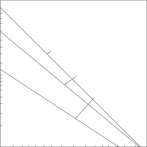
- •Chart D-1 Flexibility Factor, k, and Stress Intensification Factor, i
- •Chart D-2 Correction Factor, c
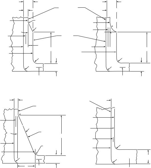
- •Fig. D-1 Branch Connection Dimensions
- •NONMANDATORY APPENDICES
- •INDEX
- •ASME B31.1 INTERPRETATIONS VOLUME 45
- •B31.1 — Cases No. 35
ASME B31.1-2010
Chart D-1 Flexibility Factor, k, and Stress Intensification Factor, i
|
|
100 |
|
|
|
|
|
|
|
|
|
|
|
|
|
|
|
|
|
|
70 |
|
|
|
|
|
|
|
|
|
|
|
|
|
|
|
|
|
|
60 |
|
|
|
|
|
|
|
|
|
|
|
|
|
|
|
|
|
|
50 |
|
|
|
|
|
|
|
|
|
|
|
|
|
|
|
|
|
|
40 |
|
|
|
|
|
|
|
|
|
|
|
|
|
|
|
|
|
k |
30 |
|
|
|
|
|
|
|
|
|
|
|
|
|
|
|
|
|
|
|
|
|
|
|
|
|
|
|
|
|
|
|
|
|
|
|
---`,,`,,`,`,,`-`-`,,```````,,```,`,`,,,,`,`,`,`-- |
Factor,i, and Flexibility Factor, |
25 |
|
|
|
|
|
|
|
|
|
|
|
|
|
|
|
|
20 |
|
|
|
|
|
Flexibility factor for elbows |
|
|
|
|
|
|
|
|||||
|
|
|
|
|
|
k = 1.65/h |
|
|
|
|
|
|
|
|
|
|||
15 |
|
|
|
|
|
|
|
|
|
|
|
|
|
|
|
|
||
10 |
|
|
|
|
|
|
|
|
Flexibility factor for miters |
|
|
|
|
|||||
9 |
|
|
|
|
|
|
|
|
k = 1.52/h5/6 |
|
|
|
|
|
|
|||
|
Intensification |
8 |
|
|
|
|
|
|
|
|
|
|
|
|
|
|
|
|
|
7 |
|
|
|
|
|
|
|
|
|
|
|
|
|
|
|
|
|
|
6 |
|
|
|
|
|
|
|
|
|
|
|
|
|
|
|
|
|
|
5 |
|
|
|
|
|
|
|
|
|
Stress intensification factor |
|
|
|||||
|
|
|
|
|
|
|
|
|
|
|
|
i = 0.9/h2/3 |
|
|
|
|
||
|
Stress |
4 |
|
|
|
|
|
|
|
|
|
|
|
|
|
|
||
|
|
|
|
|
|
|
|
|
|
|
|
|
|
|
|
|
||
|
|
|
|
|
|
|
|
|
|
|
|
|
|
|
|
|
|
|
|
|
3 |
|
|
|
|
|
|
|
|
|
|
|
|
|
|
|
|
|
|
2 |
|
|
|
|
|
|
|
|
|
|
|
|
|
|
|
|
|
|
1 |
|
|
|
|
|
|
|
|
|
|
|
|
|
|
|
|
|
|
0.01 |
0.03 |
0.04 |
0.05 |
0.06 |
0.08 |
0.10 |
0.14 |
0.2 |
0.3 |
0.4 |
0.5 |
0.6 |
0.8 |
1.0 |
1.4 |
2.0 |
Characteristic, h
224
Copyright ASME International
Provided by IHS under license with ASME
No reproduction or networking permitted without license from IHS

ASME B31.1-2010
|
|
|
|
|
|
|
|
|
|
|
Chart D-2 Correction Factor, c |
|
|
|
|
|
|
|
|
|
|
|
|
||||||||
|
1.00 |
|
|
|
|
|
|
|
|
|
|
|
|
|
|
|
|
|
|
|
|
|
|
|
|
|
|
|
|
|
|
|
|
|
|
|
|
|
|
|
|
|
|
|
|
|
|
|
|
|
|
|
|
|
|
|
|
|
|
|
|
|
|
|
|
|
|
|
|
|
|
|
|
|
|
|
|
|
|
|
|
|
|
|
|
|
|
|
|
|
|
|
|
|
|
|
0.90 |
|
|
|
|
|
|
|
|
|
|
|
|
|
|
|
|
|
|
|
|
|
|
|
|
|
|
|
|
|
|
|
|
|
|
|
|
|
|
|
|
|
|
|
|
|
|
|
|
|
|
|
|
|
|
|
|
|
|
|
|
|
|
c |
0.80 |
|
|
|
|
|
One end flanged c = h1/6 |
|
|
|
|
|
|
|
|
|
|
|
|
|
|
|
|
||||||||
|
|
|
|
|
|
|
|
|
|
|
|
|
|
|
|
|
|
|
|
||||||||||||
0.70 |
|
|
|
|
|
|
|
|
|
|
|
|
|
|
|
|
|
|
|
|
|
|
|
|
|
|
|
|
|
|
|
Factor, |
|
|
|
|
|
|
|
|
|
|
|
|
|
|
|
|
|
|
|
|
|
|
|
|
|
|
|
|
|
|
|
|
|
|
|
|
|
|
|
|
|
|
|
|
|
|
|
|
|
|
|
|
|
|
|
|
|
|
|
|
|
||
0.60 |
|
|
|
|
|
|
|
|
|
|
|
|
|
|
|
|
|
|
|
|
|
|
|
|
|
|
|
|
|
|
|
Correction |
|
|
|
|
|
|
|
|
|
|
|
|
|
|
|
|
|
|
|
|
|
|
|
|
|
|
|
|
|
|
|
0.50 |
|
|
Both ends flanged c = h1/3 |
|
|
|
|
|
|
|
|
|
|
|
|
|
|
|
|
|
|
|
|
|
|
||||||
|
|
|
|
|
|
|
|
|
|
|
|
|
|
|
|
|
|
|
|
|
|
|
|
|
|||||||
|
|
|
|
|
|
|
|
|
|
|
|
|
|
|
|
|
|
|
|
|
|
|
|
|
|
||||||
|
0.30 |
|
|
|
|
|
|
|
|
|
|
|
|
|
|
|
|
|
|
|
|
|
|
|
|
|
|
|
|
|
|
|
|
|
|
|
|
|
|
|
|
|
|
|
|
|
|
|
|
|
|
|
|
|
|
|
|
|
|
|
|
|
|
|
0.25 |
|
|
|
|
|
|
|
|
|
|
|
|
|
|
|
|
|
|
|
|
|
|
|
|
|
|
|
|
|
|
|
|
|
|
|
|
|
|
|
|
|
|
|
|
|
|
|
|
|
|
|
|
|
|
|
|
|
|
|
|
|
|
|
|
|
|
|
|
|
|
|
|
|
|
|
|
|
|
|
|
|
|
|
|
|
|
|
|
|
|
|
|
|
|
|
0.01 |
0.03 |
0.04 |
0.05 |
0.06 |
0.08 |
0.10 |
0.14 |
0.20 |
0.30 |
0.40 |
0.50 |
0.60 |
0.80 |
1.0 |
||||||||||||||||
|
|
|
|
|
|
|
|
|
|
|
|
|
|
|
|
Characteristic, h |
|
|
|
|
|
|
|
|
|
|
|
|
|||
225
--`,,```````,,```,`,`,,,,`,`,`,`-`-`,,`,,`,`,,`---
Copyright ASME International
Provided by IHS under license with ASME
No reproduction or networking permitted without license from IHS
ASME B31.1-2010
Fig. D-1 Branch Connection Dimensions
|
Tb |
|
|
tnb |
Branch pipe |
|
|
|
Db |
r3 |
Db |
|
|
|
|
n 45 deg |
r’ |
|
|
m |
r’ |
|
Branch |
m |
|
|
ri |
Offset |
ri |
rp |
L1 |
rp |
|
||
|
r2 |
|
|
r1 |
tnh |
|
|
Rm
(a)
Tb = tnb + 0.667y
tnb |
Branch |
Branch pipe
Db 
 r3
r3
r’
Db
m
|
n 45 deg |
|
rp |
|
Branch |
|
|
|
|
L1 |
r’ |
|
|
|
m |
ri |
r2 |
|
|
|
|
ri |
|
rp |
|
|
|
r1 |
|
tnh |
|
|
|
|
|
y |
Rm |
|
|
|
|
|
Tb

 tnb
tnb
 r3
r3
 n = 90 deg

 Offset
L1
r2
r1 |
tnh |
|
Rm
(b)
 tnb = Tb
r2
r1  tnh
tnh
Rm
(c)
Db = outside diameter of branch pipe, in. (mm) L1 = height of nozzle, in. (mm)
Rm = mean radius of run pipe, in. (mm) Tb = effective thickness of branch
reinforcement, in. (mm)
ri = inside radius of branch, in. (mm)
r'm = mean radius of branch pipe, in. (mm)
(d)
r1, r2, r3 = transition radii of branch reinforcement, in. (mm) rp = outside radius of branch reinforcement, in. (mm)
tnb = nominal thickness of branch pipes, in. (mm) tnh = nominal thickness of run pipe, in. (mm)
n = transition angle of branch reinforcement, deg
226
--`,,```````,,```,`,`,,,,`,`,`,`-`-`,,`,,`,`,,`---
Copyright ASME International
Provided by IHS under license with ASME
No reproduction or networking permitted without license from IHS

ASME B31.1-2010
MANDATORY APPENDIX F |
(10) |
REFERENCED STANDARDS |
|
Specific editions of standards incorporated in this Code by reference are shown in this issue of Appendix F. It is not practical to refer to a specific edition of each standard throughout the Code text, but instead, the specific edition reference dates are shown here. Appendix F will be revised at intervals as needed and issued. The names and addresses of the sponsoring organizations are also shown in this issue.
American National Standard |
ASTM Specifications [Note (1)] |
ASTM Specifications [Note (1)] |
|
(Cont’d) |
(Cont’d) |
Z223.1-1999 |
|
|
|
A 307-07b |
A 815/A 815M-07a |
ASCE/SEI Standard |
A 312/A 312M-07 |
|
|
A 320/A 320M-07a |
A 928/A 928M-05 |
7-05 |
A 322-07 |
A 992/A 992M-06a |
|
A 333/A 333M-05 |
|
ASTM Specifications [Note (1)] |
A 335/A 335M-06 |
B 26/B 26M-05 |
|
A 336/A 336M-07 |
B 32-04 |
A 36/A 36M-05 |
A 350/A 350M-04a |
B 42-02 |
A 47/A 47M-99 (R04) |
A 351/A 351M-06 |
B 43-98 (R04) |
A 48/A 48M-03 |
A 354-07 |
B 61-02 |
A 53/A 53M-07 |
A 358/A 358M-05 |
B 62-02 |
|
A 369/A 369M-06 |
B 68-02 |
A 105/A 105M-05 |
A 376/A 376M-06 |
B 68M-99 (R05) |
A 106/A 106M-06a |
A 377-03 |
B 75-02 |
A 125-96 (R07) |
A 387/A 387M-06a |
B 88-03 |
A 126-04 |
A 389/A 389M-03 |
B 88M-05 |
A 134-96 (R05) |
A 395/A 395M-99 (R04) |
|
A 135/A 135M-06 |
|
B 108-06 |
A 139/A 139M-04 |
A 403/A 403M-07 |
B 111/B 111M-04 |
A 178/A 178M-02 |
A 409/A 409M-01 (R05) |
B 148-97 |
A 179/A 179M-90a (R05) |
A 420/A 420M-07 |
B 150/B 150M-03 |
A 181/A 181M-06 |
A 426/A 426M-07 |
B 151/B 151M-05 |
A 182/A 182M-07a |
A 437/A 437M-06 |
B 161-05 |
A 192/A 192M-02 |
A 449-07b |
B 163-04 |
A 193/A 193M-07 |
A 450/A 450M-04a |
B 165-05 |
A 194/A 194M-07a |
A 451/A 451M-06 |
B 166-06 |
A 197/A 197M-00 (R06) |
A 453/A 453M-04 |
B 167-06 |
|
A 479/A 479M-06a |
B 168-06 |
A 210/A 210M-02 |
|
B 171-04 |
A 213/A 213M-07a |
A 515/A 515M-03 |
|
A 214/A 214M-96 (R05) |
A 516/A 516M-06 |
B 209/B 209M-06 |
A 216/A 216M-07 |
A 530/A 530M-04a |
B 210-04 |
A 217/A 217M-07 |
A 564/A 564M-04 |
B 210M-05 |
A 229/A 229M-99 |
A 575-96 (R02) |
B 221-06 |
A 234/A 234M-07 |
A 576-90b (R06) |
B 234-04 |
A 240/A 240M-07 1 |
A 587-96 (R05) |
B 234M-04 |
A 242/A 242M-04 1 |
|
B 241/B 241M-02 |
A 249/A 249M-07 |
A 671-06 |
B 247-02a |
A 254-97 (R02) |
A 672-06 |
B 247M-02a |
A 268/A 268M-05a |
A 691-98 (R02) |
B 251-02 1 |
A 276-06 |
|
B 251M-97 (R03) |
A 278/A 278M-01 (R06) |
A 714-99 (R03) |
B 265-07 |
A 283/A 283M-00 |
A 789/A 789M-05b |
B 280-03 |
A 285/A 285M-03 |
A 790/A 790M-07 |
B 283-06 |
A 299/A 299M-04 |
|
|
-- |
|
`,,```````,,```,`,`,,,,`,`,` |
227 |
|
Copyright ASME International
Provided by IHS under license with ASME
No reproduction or networking permitted without license from IHS
ASME B31.1-2010
(10) |
Referenced Standards (Cont’d) |
|
ASTM Specifications [Note (1)] |
ASTM Specifications [Note (1)] |
ASME Codes & Standards |
(Cont’d) |
(Cont’d) |
|
|
|
Boiler and Pressure Vessel Code, |
B 302-07 |
B 804-02 |
2001 Edition, including |
B 315-06 |
B 828-02 |
Addenda |
B 338-06a |
B 861-06a |
|
B 348-06a |
B 862-06b 1 |
B1.1-1989 |
B 361-02 |
|
B1.13M-2001 |
B 366-04b 1 |
ASTM Standard Test Methods |
B1.20.1-1983 (R01) |
B 367-06 |
|
(ANSI/ASME B1.20.1) |
B 381-06a |
D 323-06 |
B1.20.3-1976 (R98) |
|
E 94-04 |
(ANSI B1.20.3) |
B 407-04 |
E 125-85 (R04) |
B16.1-2005 |
B 408-06 |
E 186-04 |
B16.3-1998 |
B 409-06 1 |
E 280-04 |
B16.4-2005 |
B 423-05 |
E 446-04 |
B16.5-2003 |
B 424-05 |
|
B16.9-2001 |
B 425-99 (R05) |
MSS Standard Practices |
B16.10-2000 |
B 435-06 |
|
B16.11-2005 |
B 443-00 (R05) |
SP-6-06 |
B16.14-1991 |
B 444-06 |
SP-9-08 |
B16.15-1985 (R94) |
B 446-03 (R08) |
SP-25-98 |
(ANSI/ASME B16.15) |
B 462-06 |
SP-42-04 |
B16.18-1984 (R94) |
B 463-04 |
SP-43-08 |
(ANSI B16.18) |
B 464-05 |
SP-45-03 |
B16.20-1998 |
B 466/B 466M-07 |
SP-51-07 |
B16.21-2005 |
B 467-88 (R03) |
SP-53-99 (R07) |
B16.22-2001 (R05) |
B 468-04 |
SP-54-99 (R07) |
B16.24-2001 |
B 473-07 |
SP-55-06 |
B16.25-2003 |
|
SP-58-02 |
B16.34-2004 |
B 546-04 |
SP-61-03 |
B16.42-1998 |
B 547/B 547M-02 |
SP-67-02a |
B16.47-1996 (98A) |
B 564-06a |
SP-68-97 (R04) |
B16.48-2005 |
B 572-06 |
SP-69-03 |
B16.50-2001 |
B 584-06a |
SP-75-04 |
|
|
SP-79-04 |
B18.2.1-1996 (99A) |
B 608-07 |
SP-80-08 |
B18.2.2-1987 (R99) |
B 619-06 |
SP-83-06 |
(ASME/ANSI B18.2.2) |
B 622-06 |
SP-88-93 (R01) |
B18.2.3.5M-1979 (R01) |
B 625-05 |
SP-89-03 |
B18.2.3.6M-1979 (R01) |
B 626-06 |
SP-93-99 (R04) |
B18.2.4.6M-1979 (R98) |
B 649-06 |
SP-94-92 |
B18.21.1-1999 |
B 673-05 1 |
SP-95-06 |
B18.22M-1981 |
B 674-05 |
SP-97-06 |
B18.22.1-1965 (R98) |
B 675-02 |
SP-105-96 (R05) |
|
B 676-03 |
SP-106-03 |
B31.3-2002 |
B 677-05 |
|
B31.4-2002 |
B 688-96 (R04) |
AWS Specifications |
B31.8-1999 |
B 690-02 |
|
B36.10M-2004 |
B 691-95 |
A3.0-01 |
B36.19M-2004 |
|
D10.10-99 |
|
B 704-03 |
QC1-07 |
TDP-1-1998 |
B 705-05 |
|
|
B 729-05 |
API Specification |
|
5L, 38th Edition, 1990
-- |
|
`,-`-`,,```````,,```,`,`,,,,`,`,`,` |
228 |
|
Copyright ASME International
Provided by IHS under license with ASME
No reproduction or networking permitted without license from IHS
ASME B31.1-2010
|
Referenced Standards (Cont’d) |
(10) |
|
AWWA and ANSI/AWWA |
AWWA and ANSI/AWWA |
National Fire Codes |
|
Standards |
Standards (Cont’d) |
|
|
|
|
NFPA 54/ANSI Z223.1-06 |
|
C110/A21.10-98 |
C300-97 |
NFPA 85-04 |
|
C111/A21.11-95 |
C301-99 |
NFPA 1963-03 |
|
C115/A21.15-99 |
C302-95 |
|
|
C150/A21.50-96 |
C304-99 |
PFI Standards |
|
C151/A21.51-96 |
|
|
|
C153/A21.53-94 |
C500-93(95a) |
ES-16-08 |
|
|
C504-94 |
ES-24-08 |
|
C200-97 |
C509-94 |
|
|
C207-94 |
|
FCI Standard |
|
C208-96 |
C600-99 |
|
|
|
C606-97 |
79-1-03 |
|
|
|
|
|
GENERAL NOTE: The issue date shown immediately following the hyphen after the number of the standard (e.g., B1.1-1989, A 36-89, SP-6-96) is the effective date of issue (edition) of the standard. B18.2.2-1987 (R99) designates specification reaffirmed without change in 1999.
NOTE:
(1)For boiler external piping material application, see para. 123.2.2.
Specifications and standards of the following organizations appear in this Appendix:
AISC |
American Institute of Steel Construction, Inc. |
|
|
One East Wacker Drive |
|
|
Chicago, IL 60601-1802 |
|
|
Phone: 312 670-2400 |
|
|
Fax: 312 670-5403 |
|
|
www.aisc.org |
|
ANSI |
American National Standards Institute |
|
|
25 West 43rd Street, 4th Floor |
|
|
New York, NY 10036 |
|
|
Phone: 212 642-4900 |
|
|
Fax: 212 398-0023 |
|
|
www.ansi.org |
|
API |
American Petroleum Institute |
|
|
1220 L Street, NW |
|
|
Washington, DC 20005-4070 |
|
|
Phone: 202 682-8000 |
|
|
www.api.org |
|
ASCE |
American Society of Civil Engineers |
|
|
1801 Alexander Bell Drive |
|
|
Reston, VA 20191-4400 |
|
|
Phone: 800 548-2723 |
|
|
703 295-6300 (International) |
|
|
Fax: 703 295-6222 |
|
ASME |
The American Society of Mechanical Engineers |
|
-- |
Three Park Avenue |
|
`,,```````,,```,`,`,,,,`,`,`,` |
Box 2900 |
|
|
New York, NY 10016-5990 |
|
|
ASME Order Department |
|
|
22 Law Drive |
|
-`- |
Fairfield, NJ 07007-2900 |
|
`,,`,,`,`,,` |
||
Phone: 973 882-1167 |
||
|
||
--- |
800-843-2763 (US & Canada) |
|
Fax: 973 882-1717, 5155 |
||
|
||
|
www.asme.org |
ASTM |
American Society for Testing and Materials |
|
100 Barr Harbor Drive |
|
P.O. Box C700 |
|
West Conshohocken, PA 19428-2959 |
|
Phone: 610 832-9585 |
|
Fax: 610 832-9555 |
|
www.astm.org |
AWS |
American Welding Society |
|
550 NW LeJeune Road |
|
Miami, FL 33126 |
|
Phone: 305 443-9353 or 800 443-9353 |
|
www.aws.org |
AWWA |
American Water Works Association |
|
6666 W. Quincy Avenue |
|
Denver, CO 80235 |
|
Phone: 303 794-7711 or 800 926-7337 |
|
www.awwa.org |
FCI |
Fluid Controls Institute, Inc. |
|
1300 Sumner Avenue |
|
Cleveland, OH 44115-2851 |
|
Phone: 216 241-7333 |
|
Fax: 216 241-0105 |
|
www.fluidcontrolsinstitute.org |
MSS |
Manufacturers Standardization Society of |
|
the Valve and Fittings Industry, Inc. |
|
127 Park Street, NE |
|
Vienna, VA 22180-4602 |
|
Phone: 703 281-6613 |
|
www.mss-hq.com |
NFPA |
National Fire Protection Association |
|
1 Batterymarch Park |
|
Quincy, MA 02169-7471 |
|
Phone: 617 770-3000 or 800-344-3555 |
|
Fax: 617 770-0700 |
|
www.nfpa.org |
229
Copyright ASME International
Provided by IHS under license with ASME
No reproduction or networking permitted without license from IHS
|
ASME B31.1-2010 |
(10) |
Referenced Standards (Cont’d) |
PFI |
Pipe Fabrication Institute |
|
USA Office: 511 Avenue of the Americas, #601 |
|
New York, NY 10011 |
|
Canada Office: 655-32nd Ave., #201 |
|
Lachine, QC H8T 3G6 |
|
Phone: 514 634-3434 or 866 913-3434 |
|
Fax: 514 634-9736 |
|
www.pfi-institute.org |
PPI |
Plastics Pipe Institute |
|
105 Decker Court, Suite 825 |
|
Irving, TX 75062 |
|
Phone: 469 499-1044 |
|
Fax: 469 499-1063 |
|
www.plasticpipe.org |
SEI |
Structural Engineering Institute of ASCE |
|
1801 Alexander Bell Drive |
|
Reston, VA 20191-4400 |
|
Phone: 800 548-2723 |
|
Fax: 703 295-6361 |
|
www.seinstitute.org |
230
--`,,```````,,```,`,`,,,,`,`,`,`-`-`,,`,,`,`,,`---
Copyright ASME International
Provided by IHS under license with ASME
No reproduction or networking permitted without license from IHS

ASME B31.1-2010
MANDATORY APPENDIX G |
(10) |
NOMENCLATURE |
|
This Appendix is a compilation of the nomenclature used within this Code. Included are the term definitions and units that can be uniformly applied. These terms are also defined at a convenient location within the Code. When used elsewhere within the Code, definitions given here shall be understood to apply.
|
|
|
Units |
|
References |
||
Symbol |
Definition |
SI |
U.S. |
|
Paragraph |
Table/Fig./App. |
|
|
|
|
|
|
|
|
|
A |
Corrosion, erosion, and mechanical allowances |
mm |
in. |
104.1.2(A)[eqs. (3), |
104.3.1(G) |
||
|
(including threading, grooving) |
|
|
(4), (7), (8), (9), |
|
|
|
|
|
|
|
(10)] |
|
|
|
104.3.1(D.2)
104.3.1(G)
104.4.1(B) 104.5.2(B)[eq. (13)] 104.5.3(A)
Area available for reinforcement: |
mm2 |
in.2 |
|
A1 |
in run pipe |
||
A2 |
in branch pipe |
mm2 |
in.2 |
A3 |
by deposited metal beyond outside diameter of |
mm2 |
in.2 |
|
run and branch and for fillet weld attachments |
|
|
|
of rings, pads, and saddles |
|
|
A4 |
by reinforcing ring, pad, or integral reinforcement |
mm2 |
in.2 |
A5 |
in saddle on right angle connection |
mm2 |
in.2 |
A6 |
Pressure design area expected at the end of ser- |
mm2 |
in.2 |
|
vice life |
|
|
A7 |
Required reinforcement area |
mm2 |
in.2 |
B |
Length of miter segment at crotch |
mm |
in. |
b |
Subscript referring to branch |
. . . |
. . . |
C |
Cold-spring factor |
. . . |
. . . |
Cx |
Size of fillet weld for socket welding components |
mm |
in. |
|
other than flanges |
|
|
c |
Flanged elbow correction factor |
. . . |
. . . |
D |
Nominal pipe size |
mm |
in. |
D1,2 |
Outside diameter of reducer |
mm |
in. |
Dn |
Nominal outside diameter of pipe |
mm |
in. |
104.3.1(D.2.3) |
104.3.1(D) |
104.3.1(G.6) |
104.3.1(G) |
104.3.1(D.2.3) |
104.3.1(D) |
104.3.1(G.6) |
104.3.1(G) |
104.3.1(D.2.3) |
104.3.1(D) |
104.3.1(D.2.3) |
104.3.1(D) |
104.3.1(G.6) |
104.3.1(G) |
104.3.1(D.2.3) |
104.3.1(D) |
104.3.1(D.2) |
104.3.1(D) |
104.3.1(D.2.2) |
104.3.1(D) |
104.3.1(G.5) |
104.3.1(G) |
104.3.3(A&B) |
App. D, Table D-1 |
104.3.1(D.2) |
104.3.1(D) |
119.10.1[eqs. (18), |
. . . |
(19)] |
|
. . . |
127.4.4(C) |
. . . |
Table D-1 |
|
Chart D-2 |
119.7.1(A.3) |
. . . |
. . . |
App. D, Table D-1 |
102.3.2(D) |
. . . |
231 |
--`,,```````,,```,`,`,,,,`,`,`,`-`-`,,`,,`,`,,`--- |
Copyright ASME International
Provided by IHS under license with ASME
No reproduction or networking permitted without license from IHS

Symbol
|
Do |
|
Dob |
|
Doh |
|
d |
|
d1 |
|
d2 |
|
d5 |
|
d6 |
|
db |
|
dc |
|
di |
|
dn |
|
dr |
|
E |
|
E |
-- |
|
`-`,,```````,,```,`,`,,,,`,`,`,` |
h |
|
F |
|
f |
- |
|
---`,,`,,`,`,,` |
h |
|
|
|
h |
|
ho |
|
I |
|
i |
|
j |
|
K |
|
k |
|
k |
|
L |
|
L1 |
|
L4 |
|
L8 |
ASME B31.1-2010
|
|
|
Units |
|
References |
|
Definition |
|
SI |
U.S. |
|
Paragraph |
Table/Fig./App. |
Outside diameter of pipe |
mm |
in. |
102.3.2(D) |
App. D, Table D-1 |
||
|
|
|
|
|
104.1.2(A)[eqs. (7), |
104.1.2(A) |
|
|
|
|
(9)] |
|
|
|
|
|
|
|
104.8.1[eq. (15)] |
|
|
|
|
|
|
104.8.2[eq. (16)] |
|
Outside diameter of branch |
mm |
in. |
104.3.1(D.2) |
App. D, Fig. D-1 |
||
|
|
|
|
|
104.3.1(D.2.3) |
104.3.1(G) |
|
|
|
|
|
104.3.1(E) |
|
|
|
|
|
|
104.3.1(G.4) |
|
|
|
|
|
|
104.3.1(G.5) |
|
Outside diameter of header or run pipe |
mm |
in. |
104.3.1(D.2) |
104.3.1(G) |
||
|
|
|
|
|
104.3.1(E) |
|
|
|
|
|
|
104.3.1(G.4) |
|
|
|
|
|
|
104.3.1(G.5) |
|
Inside diameter of pipe |
mm |
in. |
104.1.2(A)[eqs. (8), |
104.1.2(A) |
||
|
|
|
|
(10)] |
|
|
Inside centerline longitudinal direction of the fin- |
mm |
in. |
104.3.1(D) |
104.3.1(D) |
||
ished branch opening in the run of the pipe |
|
|
|
|
104.3.1(E) |
|
Half-width of reinforcement zone |
mm |
in. |
104.3.1(D.2) |
104.3.1(D) |
||
Diameter of finished opening |
mm |
in. |
104.4.2 |
. . . |
||
Inside or pitch diameter of gasket |
mm |
in. |
104.5.3(A)[eq. (14)] |
104.5.3 |
||
Corroded internal diameter of branch pipe |
mm |
in. |
104.3.1(G.4) |
104.3.1(G) |
||
Corroded internal diameter of extruded outlet |
mm |
in. |
104.3.1(G.4) |
104.3.1(G) |
||
|
|
|
|
104.3.1(G.5) |
|
|
|
|
|
|
104.3.1(G.6) |
|
|
Inside diameter of Y-globe valve |
mm |
in. |
. . . |
122.1.7(C) |
||
Nominal inside diameter of pipe |
mm |
in. |
102.3.2(D) |
. . . |
||
Corroded internal diameter of run |
mm |
in. |
104.3.1(G.4) |
104.3.1(G) |
||
Weld joint efficiency factor |
. . . |
. . . |
104.1.2(A.5) |
102.4.3 |
||
|
|
|
|
|
|
App. A Notes and |
|
|
|
|
|
|
Tables |
Young’s modulus of elasticity (used with sub- |
MPa |
psi |
119.6.2 |
App. C, Tables |
||
scripts) |
|
|
|
119.6.4 |
C-1 and C-2 |
|
|
|
|
|
|
119.10.1[eqs. (18), |
App. D, Table D-1 |
|
|
|
|
(19)] |
|
|
Casting quality factor |
. . . |
. . . |
104.1.2(A.5) |
App. A Notes and |
||
|
|
|
|
|
|
Tables |
Stress range reduction factor |
. . . |
. . . |
102.3.2(C)[eq. (1)] |
102.3.2(C) |
||
Subscript referring to run or header |
. . . |
. . . |
104.3.1(D.2) |
104.3.1(D) |
||
|
|
|
|
|
|
104.3.1(G) |
Thread depth (ref. ASME B1.20.1) |
mm |
in. |
102.4.2 |
. . . |
||
Flexibility characteristic, to compute i, k |
. . . |
. . . |
. . . |
App. D, Table D-1 |
||
Height of extruded lip |
mm |
in. |
104.3.1(G.2) |
104.3.1(G) |
||
|
|
|
|
|
104.3.1(G.4) |
|
Lorenz equation compensation factor |
. . . |
. . . |
102.4.5[eqs. (3), (4), |
. . . |
||
|
|
|
|
(5), (6)] |
|
|
Stress intensification factor |
. . . |
. . . |
104.8.1[eq. (15)] |
App. D, Table D-1 |
||
|
|
|
|
104.8.2[eq. (16)] |
|
|
|
|
|
|
104.8.3[eq. (17)] |
|
|
|
|
|
|
104.8.4(C) |
|
|
Subscript for resultant moment |
. . . |
. . . |
104.8.4(A) |
. . . |
||
Factor for reinforcing area |
. . . |
. . . |
104.3.1(G.5) |
104.3.1(G) |
||
Factor for occasional loads |
. . . |
. . . |
104.8.2[eq. (16)] |
. . . |
||
Flexibility factor |
. . . |
. . . |
. . . |
App. D, Table D-1 |
||
Developed length of line axis |
m |
ft |
119.7.1(A.3) |
. . . |
||
Height of nozzle |
mm |
in. |
104.8.4(C) |
App. D, Fig. D-1 |
||
Altitude of reinforcing zone outside run pipe |
mm |
in. |
104.3.1(D.2) |
104.3.1(D) |
||
Altitude of reinforcing zone for extruded outlet |
mm |
in. |
104.3.1(G.4) |
104.3.1(G) |
||
|
|
|
|
104.3.1(G.6) |
|
|
232
Copyright ASME International
Provided by IHS under license with ASME
No reproduction or networking permitted without license from IHS

ASME B31.1-2010
|
|
|
|
Units |
|
References |
|
Symbol |
Definition |
|
SI |
U.S. |
|
Paragraph |
Table/Fig./App. |
|
|
|
|
|
|
||
M |
Moment of bending or torsional force (used with |
mm·N |
in.-lb |
104.8.1[eq. (15)] |
104.8.4 |
||
|
subscripts to define applications as shown in |
|
|
|
104.8.2[eq. (16)] |
|
|
|
referenced paragraphs) |
|
|
|
104.8.3[eq. (17)] |
|
|
|
|
|
|
|
104.8.4(A) |
|
|
|
|
|
|
|
104.8.4(C) |
|
|
MAWP |
Maximum allowable working pressure |
kPa |
psi |
100.2 |
. . . |
||
MSOP |
Maximum sustained operating pressure |
kPa |
psi |
101.2.2 |
. . . |
||
N |
Total number of equivalent reference displace- |
. . . |
. . . |
102.3.2(C)[eq. (2)] |
102.3.2(C) |
||
|
ment stress range cycles |
|
|
|
|
|
|
NE |
Number of cycles of reference displacement |
. . . |
. . . |
102.3.2(C)[eq. (2)] |
. . . |
||
|
stress range |
|
|
|
|
|
|
Ni |
Number of cycles associated with displacement |
. . . |
. . . |
102.3.2(C)[eq. (2)] |
. . . |
||
|
stress range |
|
|
|
|
|
|
NPS |
Nominal pipe size |
. . . |
in. |
General |
. . . |
||
P |
Internal design gage pressure of pipe, component |
kPa |
psi |
102.3.2(D) |
App. D, Table D-1 |
||
|
|
|
|
|
104.1.2(A)[eqs. (7), |
|
|
|
|
|
|
|
(8), (9), (10)] |
|
|
|
|
|
|
|
104.5.1(A) |
|
|
|
|
|
|
|
104.5.2(B) |
|
|
|
|
|
|
|
104.5.3(A)[eq. (14)] |
|
|
|
|
|
|
|
104.5.3(B) |
|
|
|
|
|
|
|
104.8.1[eq. (15)] |
|
|
|
|
|
|
|
104.8.2[eq. (16)] |
|
|
|
|
|
|
|
122.1.2(A) |
|
|
|
|
|
|
|
122.1.3(A) |
|
|
|
|
|
|
|
122.1.4(A) |
|
|
|
|
|
|
|
122.1.4(B) |
|
|
|
|
|
|
|
122.1.6(B) |
|
|
|
|
|
|
|
122.1.7(C) |
|
|
|
|
|
|
|
122.4(B) |
|
|
q |
Ratio of partial T to maximum T (used with |
. . . |
. . . |
102.3.2(C)[eq. (2)] |
. . . |
||
|
subscripts) |
|
|
|
|
|
|
R |
Reaction moment in flexibility analysis (used with |
mm-N |
in.-lb |
119.10.1[eqs. (18), |
. . . |
||
|
subscripts) |
|
|
|
(19)] |
|
|
R |
Centerline radius of elbow or bend, and effective |
mm |
in. |
102.4.5(B) |
App. D, Table D-1 |
||
|
“radius” of miter bends |
|
|
|
104.3.3(C.3.1) |
102.4.5 |
|
Rm |
Mean radius of run pipe |
|
mm |
in. |
. . . |
App. D, Fig. D-1 |
|
|
|
|
|
|
|
|
App. D, Table D-1 |
r |
Mean radius of pipe using nominal wall tn |
|
mm |
in. |
104.3.3 |
App. D, Table D-1 |
|
r1 |
Half width of reinforcement zone |
|
mm |
in. |
104.3.1(G.4) |
104.3.1(G) |
|
r1, r2, r3 |
Transition radii of branch reinforcement |
|
mm |
in. |
. . . |
App. D, Fig. D-1 |
|
rb |
Branch mean cross-sectional radius |
|
mm |
in. |
104.8.4 |
. . . |
|
ri |
Inside radius of branch |
|
mm |
in. |
104.8.4(C) |
App. D, Fig. D-1 |
|
r ′m |
Mean radius of branch |
|
mm |
in. |
104.8.4(C) |
App. D, Fig. D-1 |
|
|
|
|
|
|
|
|
App. D, Table D-1 |
ro |
Radius of curvature of external curved portion |
mm |
in. |
104.3.1(G.2) |
104.3.1(G) |
||
|
|
|
|
|
104.3.1(G.4) |
|
|
|
|
|
|
|
104.3.1(G.6) |
|
|
rp |
Outside radius of branch reinforcement |
|
mm |
in. |
. . . |
App. D, Fig. D-1 |
|
|
|
|
|
|
|
|
App. D, Table D-1 |
--`,,```````,,```,`,`,,,,`,`,`,`-`-`,,`,,`,`,,`---233
Copyright ASME International
Provided by IHS under license with ASME
No reproduction or networking permitted without license from IHS

Symbol
rx
S
S
Sa
Sb
Sc
Sf
Sh
Slp
SA
SE
SL --`,,```````,,```,`,`,,,,`,`,`,`
SE-` -`,,`,,`,`,,` ---
SE
SF
SF
s T
Tc
ASME B31.1-2010
|
|
Units |
|
References |
|
Definition |
SI |
U.S. |
|
Paragraph |
Table/Fig./App. |
External crotch radius of welded-in contour |
mm |
in. |
. . . |
App. D |
|
inserts |
|
|
|
|
|
Basic material allowable stress |
MPa |
psi |
122.1.2(A) |
. . . |
|
|
|
|
122.1.3(B) |
|
|
|
|
|
122.4(B.3) |
|
|
Basic material allowable stress |
MPa |
ksi |
102.3.1(A) |
App. A Tables |
|
|
|
|
|
|
and Notes |
Bolt design stress at atmospheric temperature |
kPa |
psi |
104.5.1(A) |
. . . |
|
Bolt design stress at design temperature |
kPa |
psi |
104.5.1(A) |
. . . |
|
Basic material allowable stress at minimum (cold) |
MPa |
psi |
102.3.2(C)[eq. (1)] |
. . . |
|
temperature |
|
|
|
|
|
Allowable stress for flange material or pipe |
kPa |
psi |
104.5.1(A) |
. . . |
|
Basic material allowable stress at maximum (hot) |
MPa |
psi |
102.3.2(C)[eq. (1)] |
. . . |
|
temperature |
|
|
102.3.2(D) |
|
|
|
|
|
|
104.8.1[eq. (15)] |
|
|
|
|
|
104.8.2[eq. (16)] |
|
|
|
|
|
104.8.3[eq. (17)] |
|
|
|
|
|
119.10.1 [eq. (19)] |
|
Longitudinal pressure stress |
kPa |
psi |
102.3.2(D) |
. . . |
|
|
|
|
104.8 |
|
|
Allowable stress range for expansion stress |
MPa |
psi |
102.3.2(C)[eq. (1)] |
. . . |
|
|
|
|
104.8.3[eq. (17)] |
|
|
Computed thermal expansion stress range |
MPa |
psi |
104.8.3[eq. (17)] |
. . . |
|
|
|
|
119.6.4 |
|
|
|
|
|
119.10.1[eq. (19)] |
|
|
Longitudinal stress due to pressure, weight, and |
MPa |
psi |
102.3.2(D) |
. . . |
|
other sustained loads |
|
|
|
104.8.1[eq. (15)] |
|
Allowable stress (including weld joint efficiency |
MPa |
psi |
102.3.2(C) |
. . . |
|
factor) |
|
|
|
104.1.2(A)[eqs. (7), |
|
|
|
|
(8), (9), (10)] |
|
|
|
|
|
|
104.5.2(B) |
|
|
|
|
|
104.5.3(A)[eq. (14)] |
|
|
|
|
|
104.5.3(B) |
|
Allowable stress (including weld joint efficiency |
MPa |
ksi |
102.3.1(A) |
App. A Tables |
|
factor) |
|
|
|
|
and Notes |
Allowable stress (including casting quality factor) |
MPa |
psi |
104.1.2(A) |
. . . |
|
Allowable stress (including casting quality factor) |
MPa |
ksi |
102.3.1(A) |
App. A Tables |
|
|
|
|
|
|
and Notes |
Miter spacing pipe centerline |
mm |
in. |
. . . |
App. D, Table D-1 |
|
Pipe wall thickness (measured or minimum, in |
mm |
in. |
104.3.1(D.2) |
104.3.1(D) |
|
accordance with purchase specification used |
|
|
104.8.4(C) |
App. D, Fig. D-1 |
|
with or without subscripts), viz., |
|
|
|
|
|
Tbpthickness of branch |
|
|
|
|
|
Thpthickness of header, etc. |
|
|
|
|
|
Crotch thickness of welded-in contour inserts |
mm |
in. |
. . . |
App. D, Table D-1 |
|
234
Copyright ASME International
Provided by IHS under license with ASME
No reproduction or networking permitted without license from IHS

ASME B31.1-2010
|
|
|
Units |
|
References |
|
Symbol |
Definition |
SI |
U.S. |
|
Paragraph |
Table/Fig./App. |
|
|
|
|
|
|
|
To |
Corroded finished thickness extruded outlet |
mm |
in. |
104.3.1(G.4) |
104.3.1(G) |
|
|
|
|
|
104.3.1(G.6) |
|
|
t |
Pressure design thickness pipe, components |
mm |
in. |
104.1.2(A)[eqs. (7), |
104.3.1(G) |
|
|
(used with subscripts) |
|
|
(8), (9), (10)] |
104.5.3 |
|
|
|
|
|
104.3.1(D.2) |
127.4.8(D) |
|
|
|
|
|
104.3.1(G.4) |
|
|
|
|
|
|
104.3.3(C.3.1) |
|
|
|
|
|
|
104.3.3(C.3.2) |
|
|
|
|
|
|
104.4.1(B) |
|
|
|
|
|
|
104.4.2 |
|
|
|
|
|
|
104.5.2(B)[eq. (13)] |
|
|
|
|
|
|
104.5.3(A)[eq. (14)] |
|
|
|
|
|
|
104.5.3(B) |
|
|
|
|
|
|
104.8.1 |
|
|
|
|
|
|
104.8.4(C) |
|
|
|
|
|
|
127.4.8(B) |
|
|
|
|
|
|
132.4.2(E) |
|
|
t1,2 |
Nominal wall thickness of reducer |
mm |
in. |
. . . |
App. D, Table D-1 |
|
tb |
Required thickness of branch pipe |
mm |
in. |
104.3.1(G.4) |
104.3.1(G) |
|
|
|
|
|
104.3.1(G.6) |
|
|
tc |
Throat thickness of cover fillet weld, branch con- |
mm |
in. |
127.4.8(B) |
127.4.8(D) |
|
|
nection |
|
|
132.4.2(E) |
127.4.8(E) |
|
te |
Effective branch wall thickness |
mm |
in. |
104.8.4(C) |
. . . |
|
th |
Required thickness of header or run |
mm |
in. |
104.3.1(G.4) |
104.3.1(G) |
|
tm |
Minimum required thickness of component, |
mm |
in. |
104.1.2(A)[eqs. (7), |
102.4.5 |
|
|
including allowances (c) for mechanical joining, |
|
|
(8), (9), (10)] |
104.1.2(A) |
|
|
corrosion, etc. (used with subscripts), viz., |
|
|
104.3.1(D.2) |
104.3.1(D) |
|
|
tmbpminimum thickness of branch |
|
|
104.3.1(E) |
104.3.1(G) |
|
|
tmhpminimum thickness of header |
|
|
|
104.3.1(G) |
127.4.2 |
|
|
|
|
|
104.3.3(C.3.1) |
|
|
|
|
|
|
104.3.3(C.3.2) |
|
|
|
|
|
|
104.4.1(B) |
|
|
|
|
|
|
104.5.2(B)[eq. (13)] |
|
|
|
|
|
|
104.5.3(A) |
|
|
tn |
Nominal wall thickness of component (used with |
|
|
subscripts), viz., |
|
|
tnbpnominal wall thickness of branch |
|
|
tnhpnominal wall thickness of header |
|
|
tnrpnominal thickness of reinforcement |
|
tr |
Thickness of reinforcing pad or saddle |
|
ts |
Wall thickness of segment or miter |
|
tw |
Weld thickness |
|
U |
Anchor distance (length of straight line joining |
|
|
anchors) |
|
-- |
|
|
W |
Weld strength reduction factor |
Copyright ASME |
International`-`,,```````,,```,`,`,,,,`,`,`,` |
|
- |
|
|
|
-`,,`,,`,`,,` |
|
Provided by IHS under license with ASME |
|
|
No reproduction or networking permitted without license from IHS
mm |
in. |
102.3.2(D) |
127.4.4(B) |
|
|
104.3.1(G) |
127.4.4(C) |
|
|
104.3.3 |
127.4.8(D) |
|
|
104.8.1[eq. (15)] |
127.4.8(E) |
|
|
104.8.2[eq. (16)] |
App. D, Fig. D-1 |
|
|
104.8.4(C) |
App. D, Table D-1 |
|
|
127.4.8(B) |
|
|
|
132.4.2(E) |
|
mm |
in. |
104.3.1(D.2) |
104.3.1(D) |
|
|
104.3.1(E) |
App. D, Table D-1 |
mm |
in. |
104.3.3(C.3) |
. . . |
mm |
in. |
104.3.1(C.2) |
127.4.8(G) |
m |
ft |
119.7.1(A.3) |
. . . |
. . . |
. . . |
102.4.7 |
102.4.7 |
|
|
104.1.4 |
|
235

ASME B31.1-2010
|
|
|
|
Units |
|
References |
||
Symbol |
Definition |
|
SI |
U.S. |
|
Paragraph |
Table/Fig./App. |
|
|
|
|
|
|
|
|
||
xmin |
Size of fillet weld for slip-on and socket welding |
mm |
in. |
. . . |
127.4.4(B) |
|||
|
flanges or socket wall for socket welds |
|
|
|
|
|
|
|
Y |
Resultant of movement to be absorbed by pipe- |
. . . |
. . . |
119.7.1(A.3) |
. . . |
|
||
|
lines |
|
|
|
|
|
|
|
y |
A coefficient having values given in Table |
. . . |
. . . |
104.1.2(A.7)[eqs. |
104.1.2(A) |
|||
|
104.1.2(A) |
|
|
|
(7), (8), (9), (10)] |
App. A, Notes to |
||
|
|
|
|
|
|
|
Tables A-4, A-5, |
|
|
|
|
|
|
|
|
A-6, A-7, and |
|
|
|
|
|
|
|
|
A-9 |
|
y |
Branch offset dimension |
mm |
in. |
. . . |
App. D, Fig. D-1 |
|||
Z |
Section modulus of pipe |
mm3 |
in.3 |
104.8.1[eq. (15)] |
. . . |
|
||
|
|
|
|
|
104.8.2[eq. (16)] |
|
|
|
|
|
|
|
|
104.8.3[eq. (17)] |
|
|
|
|
|
|
|
|
104.8.4(A) |
|
|
|
|
|
|
|
|
104.8.4(C) |
|
|
|
|
Angle between axes of branch and run |
deg |
deg |
104.3.1(D.2) |
104.3.1(D) |
|||
|
|
|
|
|
|
104.3.1(E) |
|
|
|
Reducer cone angle |
deg |
deg |
. . . |
App. D, Table D-1 |
|||
|
Mismatch or offset |
mm |
in. |
. . . |
App. D, Table D-1 |
|||
T |
Range of temperature change (used with sub- |
°C |
°F |
102.3.2(C) |
. . . |
|
||
|
scripts) |
|
|
|
|
|
|
|
|
Angle of miter cut |
deg |
deg |
104.3.3 |
App. D, Table D-1 |
|||
n |
Transition angle of branch reinforcement |
deg |
deg |
. . . |
App. D, Fig. D-1 |
|||
≥ |
Equal to or greater than |
. . . |
. . . |
. . . |
. . . |
|
||
≤ |
Equal to or less than |
. . . |
. . . |
. . . |
. . . |
|
||
|
|
|
|
|
|
|
|
|
--`,,```````,,```,`,`,,,,`,`,`,`-`-`,,`,,`,`,,`---
236
Copyright ASME International
Provided by IHS under license with ASME
No reproduction or networking permitted without license from IHS
ASME B31.1-2010
MANDATORY APPENDIX H
PREPARATION OF TECHNICAL INQUIRIES
H-1 INTRODUCTION
The ASME B31 Committee, Code for Pressure Piping, will consider written requests for interpretations and revisions of the Code rules, and develop new rules if dictated by technical development. The CommitteeÕs activities in this regard are limited strictly to interpretations of the rules or to the consideration of revisions to the present rules on the basis of new data or technology. The Introduction to this Code states ÒIt is the ownerÕs responsibility to determine which Code Section is applicable to a piping installation.Ó The Committee will not respond to inquiries requesting assignment of a Code Section to a piping installation. As a matter of published policy, ASME does not approve, certify, rate, or endorse any item, construction, proprietary device, or activity, and, accordingly, inquiries requiring such consideration will be returned. Moreover, ASME does not act as a consultant on specific engineering problems or on the general application or understanding of the Code rules. If, based on the inquiry information submitted, it is the opinion of the Committee that the inquirer should seek professional assistance, the inquiry will be returned with the recommendation that such assistance be obtained.
Inquiries that do not provide the information needed for the CommitteeÕs full understanding will be returned.
H-2 REQUIREMENTS
Inquiries shall be limited strictly to interpretations of the rules or to the consideration of revisions to the present rules on the basis of new data or technology. Inquiries shall meet the following requirements:
237
(a)Scope. Involve a single rule or closely related rules in the scope of the Code. An inquiry letter concerning unrelated subjects will be returned.
(b)Background. State the purpose of the inquiry, which may be either to obtain an interpretation of Code rules, or to propose consideration of a revision to the present rules. Provide concisely the information needed for the CommitteeÕs understanding of the inquiry, being sure to include reference to the applicable Code Section, Edition, Addenda, paragraphs, figures, and tables. If sketches are provided, they shall be limited to the scope of the inquiry.
(c)Inquiry Structure
(1)Proposed Question(s). The inquiry shall be stated in a condensed and precise question format, omitting superfluous background information, and, where appropriate, composed in such a way that ÒyesÓ or ÒnoÓ (perhaps with provisos) would be an acceptable reply. The inquiry statement should be technically and editorially correct.
(2)Proposed Reply(ies). Provide a proposed reply stating what it is believed that the Code requires. If in the inquirerÕs opinion, a revision to the Code is needed, recommended wording shall be provided in addition to information justifying the change.
H-3 SUBMITTAL
Inquiries should be submitted in typewritten form; however, legible handwritten inquiries will be considered. They shall include the name and mailing address of the inquirer, and be mailed to the following address:
Secretary
ASME B31 Committee Three Park Avenue
New York, NY 10016-5990
--`,,```````,,```,`,`,,,,`,`,`,`-`-`,,`,,`,`,,`---
Copyright ASME International
Provided by IHS under license with ASME
No reproduction or networking permitted without license from IHS
ASME B31.1-2010
MANDATORY APPENDIX J
QUALITY CONTROL REQUIREMENTS FOR BOILER EXTERNAL PIPING (BEP)
FOREWORD
This Appendix contains the quality control requirements for boiler external piping. The following is that portion of Appendix A-300 Quality Control System of the ASME Boiler and Pressure Vessel Code, Section I, which is applicable to BEP.
J-1 QUALITY CONTROL SYSTEM
J-1.1 General
J-1.1.1 Quality Control System. The Manufacturer or assembler shall have and maintain a quality control system which will establish that all Code requirements, including material, design, fabrication, examination (by the Manufacturer), and inspection of boilers and boiler parts (by the Authorized Inspector), will be met. Provided that Code requirements are suitably identified, the system may include provisions for satisfying any requirements by the Manufacturer or user that exceed minimum Code requirements and may include provisions for quality control of non-Code work. In such systems, the Manufacturer may make changes in parts of the system that do not affect the Code requirements without securing acceptance by the Authorized Inspector. Before implementation, revisions to quality control systems of Manufacturers and assemblers of safety and safety relief valves shall have been found acceptable to an ASME designee if such revisions affect Code requirements.
-- |
|
The system that the Manufacturer or assembler uses |
|
plexity`,,```````,,```,`,`,,,,`,`,`,` |
of the work performed and on the size and com- |
to meet the requirements of this Section must be one suitable for his/her own circumstances. The necessary scope and detail of the system shall depend on the com-
-`- |
|
plexity of the Manufacturer Õs (or assembler Õs) |
|
Manufacturer`,,`,,`,`,,`--- |
or assembler will use to produce a Code |
organization. A written description of the system the
item shall be available for review. Depending upon the circumstances, the description may be brief or voluminous.
The written description may contain information of proprietary nature relating to the ManufacturerÕs (or assemblerÕs) processes. Therefore, the Code does not require any distribution of this information, except for the Authorized Inspector or ASME designee.
238
It is intended that information learned about the system in connection with evaluation will be treated as confidential and that all loaned descriptions will be returned to the Manufacturer upon completion of the evaluation.
J-1.2 Outline of Features to Be Included in the Written Description of the Quality Control System
The following is a guide to some of the features that should be covered in the written description of the quality control system and that is equally applicable to both shop and field work.
J-1.2.1 Authority and Responsibility. The authority and responsibility of those in charge of the quality control system shall be clearly established. Persons performing quality control functions shall have sufficient and well-defined responsibility, the authority, and the organizational freedom to identify quality control problems and to initiate, recommend, and provide solutions.
J-1.2.2 Organization. An organization chart showing the relationship between management and engineering, purchasing, manufacturing, field assembling, inspection, and quality control is required to reflect the actual organization. The purpose of this chart is to identify and associate the various organizational groups with the particular function for which they are responsible. The Code does not intend to encroach on the ManufacturerÕs right to establish, and from time to time to alter, whatever form of organization the Manufacturer considers appropriate for its Code work.
J-1.2.3 Drawings, Design Calculations, and Specification Control. The ManufacturerÕs or assemblerÕs quality control system shall provide procedures that will ensure that the latest applicable drawings, design calculations, specifications, and instructions, required by the Code, as well as authorized changes, are used for manufacture, assembly, examination, inspection, and testing.
J-1.2.4 Material Control. The Manufacturer or assembler shall include a system of receiving control that will ensure that the material received is properly identified and has documentation, including required material certifications or material test reports, to satisfy
Copyright ASME International
Provided by IHS under license with ASME
No reproduction or networking permitted without license from IHS
ASME B31.1-2010
Code requirements as ordered. The material control system shall insure that only the intended material is used in Code construction.
J-1.2.5 Examination and Inspection Program. The ManufacturerÕs quality control system shall describe the fabrication operations, including examinations, sufficiently to permit the Authorized Inspector to determine at what stages specific inspections are to be performed.
J-1.2.6 Correction of Nonconformities. There shall be a system agreed upon with the Authorized Inspector for correction of nonconformities. A nonconformity is any condition that does not comply with the applicable rules of this Section. Nonconformities must be corrected or eliminated in some way before the completed component can be considered to comply with this Section.
J-1.2.7 Welding. The quality control system shall include provisions for indicating that welding conforms to requirements of Section IX as supplemented by this Section.
J-1.2.8 Nondestructive Examination. The quality control system shall include provisions for identifying nondestructive examination procedures the Manufacturer will apply to conform with requirements of this Section.
J-1.2.9 Heat Treatment. The quality control system shall provide controls to ensure that heat treatments as required by the rules of this Section are applied. Means shall be indicated by which the Authorized Inspector can satisfy him/herself that these Code heat treatment requirements are met. This may be by review of furnace time Ð temperature records or by other methods as appropriate.
J-1.2.10 Calibration of Measurement and Test Equipment. The Manufacturer or assembler shall have a system for the calibration of examination, measuring, and test equipment used in fulfillment of requirements of this Section.
J-1.2.11 Records Retention. The Manufacturer or assembler shall have a system for the maintenance of radiographs and ManufacturersÕ Data Reports as required by this Section.
J-1.2.12 Sample Forms. The forms used in the quality control system and any detailed procedures for their use shall be available for review. The written description shall make necessary references to these forms.
J-1.2.13 Inspection of Boilers and Boiler Parts
J-1.2.13.1 Inspection of boilers and boiler parts shall be by the Authorized Inspector described in PG-91.
J-1.2.13.2 The written description of the quality control system shall include reference to the Authorized Inspector.
J-1.2.13.2.1 The Manufacturer (or assembler) shall make available to the Authorized Inspector at the ManufacturerÕs plant (or construction site) a current copy of the written description or the applicable quality control system.
J-1.2.13.2.2 The ManufacturerÕs quality control system shall provide for the Authorized Inspector at the ManufacturerÕs plant to have access to all drawings, calculations, specifications, procedures, process sheets, repair procedures, records, test results, and any other documents as necessary for the Inspector to perform his/her duties in accordance with this Section. The Manufacturer may provide such access either to his/her own files of such documents or by providing copies to the Inspector.
J-1.2.14 Inspection of Safety and Safety Relief Valves
J-1.2.14.1 Inspection of safety and safety relief valves shall be by designated representative of the ASME, as described in PG-73.3.
J-1.2.14.2 The written description of the quality control system shall include reference to the ASME designee.
J-1.2.14.2.1 The valve Manufacturer (or assembler) shall make available to the ASME designee at the ManufacturerÕs plant a current copy of the written description of the applicable quality control system.
J-1.2.14.2.2 The valve Manufacturer Õs (or assemblerÕs) quality control system shall provide for the ASME designee to have access to all drawings, calculations, specifications, procedures, process sheets, repair procedures, records, test results, and any other documents as necessary for the designee to perform his/her duties in accordance with this Section. The Manufacturer may provide such access either to his/her own files of such documents or by providing copies to the designee.
239
--`,,```````,,```,`,`,,,,`,`,`,`-`-`,,`,,`,`,,`---
Copyright ASME International
Provided by IHS under license with ASME
No reproduction or networking permitted without license from IHS