

БЭМЗ полищук доки / 2020 / А2000 минск / Стандарт MIL-STD-202G
.pdfMIL-STD-202G
e.Remove the iron and allow the component to cool and stabilize at room ambient conditions. If flux was used, the component shall be cleaned using an appropriate cleaning solution.
f.The component shall be visually examined under 10X magnification.
4.4.2Test condition B: Solder dip.
a.Place the component in an appropriate fixture (see 2.3).
b.When specified, the leads shall be fluxed (see 4.3).
c.The specific combination of temperature, immersion and emersion rate, immersion duration, and number of heats shall be as specified in table I. Unless otherwise specified, terminations shall be immersed to within
.050 inch (1.27 mm) of the component body. Terminations shall be immersed simultaneously, if the geometry of the component permits.
d.After the solder dip, the component shall be allowed to cool and stabilize at room ambient conditions. If flux was used, the component shall be cleaned using an appropriate cleaning solution.
e.The component shall be visually examined under 10X magnification.
4.4.3Test condition C: Wave solder - topside board mount component.
a.The component under test shall be mounted on a mounting board (see 2.4).
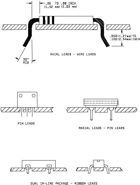
Wire leads: Wire leads shall be brought through the board holes and bent at least 30 degrees from a line
perpendicular to the board. Leads shall extend from .050 inch to .100 inch (1.27 mm to 2.54 mm) from the bottom of the board. Axial leads shall be bent at a 90° angle at a point between .06 inch and .08 inch (1.5 mm and 2.1 mm) from the body, eyelet fillet or weld unless otherwise specified (see figure 210-1).
Pin leads: Where the component is designed with rigid pin leads, the full length of the termination shall be retained. Pin leads shall not be cut or bent (see figure 210-1).
b.When specified, the leads shall be fluxed (see 4.3).
c.The specific combination of temperature, duration, and number of heats shall be as specified in table I.
d.The components, mounted on the board, shall be immersed in the solder pot so that the bottom of the board floats on the molten solder.
e.After the float, the components shall be allowed to cool and stabilize at room ambient conditions. If flux was used, the components shall be cleaned using an appropriate cleaning solution.
f.The components shall be visually examined under 10X magnification.
4.4.4Test condition D: Wave solder - bottomside board mount product.
a.Place the component in an appropriate fixture (see 2.3).
b.When specified, the terminations shall be fluxed (see 4.3).
c.The specific combination of temperature, preheat conditions, immersion and emersion rates, immersion duration, and number of heats shall be as specified in table I.
METHOD 210F
8 February 2002
3
MIL-STD-202G
d.The component shall be preheated and fully immersed in the solder bath in accordance with 4.4.4c.
e.After the immersion, the component shall be allowed to cool and stabilize at room ambient conditions. If flux was used, the component shall be cleaned using an appropriate cleaning solution.
f.The component shall be visually examined under 10X magnification.
4.4.5Test condition H: Vapor phase reflow soldering.
a.Components shall be mounted on a mounting board (see 2.4). Through-hole mounted components shall have their terminals inserted into the termination holes. Surface mount components shall be placed on top of the board.
b.A test chamber (see 2.6) shall be used which is large enough to suspend the mounting board without touching the sides or the solution. The VPR fluid shall be placed in the test chamber and shall be heated until it is boiling. The solution shall be allowed to boil for 5 minutes prior to suspending the mounting board.
c.The specific combination of temperature, duration of exposure, and number of heats shall be as specified in table I.
d.After chamber equalization, the mounting board shall be suspended into the vapor in a horizontal plane. The mounting board shall not touch the solution.
e.After the heat, the components shall be allowed to cool and stabilize at room ambient conditions. If a solder paste was used, the component shall be cleaned using an appropriate solution.
f.The components shall be visually examined under 10X magnification.
4.4.6Test conditions I, J, K: Infared/convection reflow soldering.
a.Components shall be mounted on a mounting board (see 2.4). Through-hole mounted components shall have their terminals inserted into the termination holes. Surface mount components shall be placed on top of the board.
b.A test chamber as specified in 2.6 shall be used.
c.A low mass thermocouple shall be attached tightly to the component at an appropriate position away from the edges.
d.The specific combination of temperature, preheat, duration, and number of heats shall be as specified by test condition I, J, or K in table I and the individual procurement document.
e.The board shall be placed into the test chamber and the temperature of the component ramped at a rate of 1°C/s to 4°C/s as measured by the thermocouple. The assembly shall be above 183°C for 90 seconds to 120 seconds and held at the final temperature and time designated by the test condition. The assembly shall then be allowed to cool to room ambient temperature. This constitutes one heat cycle. The assembly shall be exposed to three heat cycles.
f.The components shall be visually examined under 10X magnification.
METHOD 210F
8 February 2002
4
MIL-STD-202G
5. EXAMINATIONS AND MEASUREMENTS. Examinations and measurements to be made before and after the test, as applicable, shall be as specified in the individual specification. After the procedure, the specimens shall be allowed to cool and stabilize at room ambient conditions, for the time specified in the individual specification.
5.1 Internal examination. When specified, internal examination of the part shall be made after the test to check for solder reflow or heat damage.
6.SUMMARY. The following details are to be specified in the individual specification:
a.The use of heat sinks or shielding is prohibited except when they are part of the component (see 2.2).
b.Mounting board, if different from that specified (see 2.4).
c.Solder, if different from that specified (see 3.1).
d.Flux, if applicable and if different from that specified (see 3.2, 4.1, and 4.3).
e.Solder terminations that are not to be tested, if applicable (see 4.4).
f.Special preparation of specimens if applicable (see 4.1).
g.Depth of immersion in the molten solder, if different from that specified (see 4.4.2).
h.Test condition letter (see 4.4).
i.Cooling time prior to final examinations and measurements (see 4.4 and 5).
j.Examinations and measurements before and after test, as applicable (see 5).
k.Method of internal inspection, if required (see 5.1).
METHOD 210F
8 February 2002
5
MIL-STD-202G
TABLE I. Test conditions.
Solder technique |
Test |
Temperature |
Time |
Temperature ramp/ |
Number |
simulation |
condition |
(°C) |
(s) |
immersion and emersion |
of |
|
|
|
|
rate |
heat |
|
|
|
|
|
cycles |
Solder iron |
A |
350 ±10 |
4 - 5 |
|
1 |
|
|
(solder iron temp) |
|
|
|
Dip |
B |
260 ±5 |
10 ±1 |
25mm/s ±6 mm/s |
1 |
|
|
(solder temp) |
|
|
|
Wave: Topside |
C |
260 ±5 |
20 ±1 |
|
1 |
board-mount product |
|
(solder temp) |
|
|
|
Wave: Bottomside |
D |
260 ±5 |
10 ±1 |
Preheat 1°C/s-4°C/s to within |
1 |
board-mount product |
|
(solder temp) |
|
100°C of solder temp. |
|
|
|
|
|
25 mm/s ± 6 mm/s |
|
|
E |
CANCELLED |
|
|
|
|
F |
CANCELLED |
|
|
|
|
G |
CANCELLED |
|
|
|
Vapor phase reflow |
H |
215 ±5 |
60 ±5 |
|
1 |
|
|
(vapor temp) |
|
|
|
IR/convection reflow |
I |
215 ±5 |
30 ±5 |
1°C/s-4°C/s; time above 183°C, |
3 |
|
|
(component temp) |
|
90 s - 120 s |
|
|
J |
235 ±5 |
30 ±5 |
1°C/s-4°C/s; time above 183°C, |
3 |
|
|
(component temp) |
|
90 s - 120 s |
|
|
K |
250 ±5 |
30 ±5 |
1°C/s-4°C/s; time above 183°C, |
3 |
|
|
(component temp) |
|
90 s - 120 s |
|
Test condition E is cancelled; use test condition C.
Test condition F is cancelled; use test condition B.
Test condition G is cancelled.
METHOD 210F
8 February 2002
6
MIL-STD-202G
FIGURE 210-1. Component lead and mounting examples.
METHOD 210F
8 February 2002
7
MIL-STD-202G
METHOD 211A
TERMINAL STRENGTH
1.PURPOSE. This test is performed to determine whether the design of the terminals and their method of attachment can withstand one or more of the applicable mechanical stresses to which they will be subjected during installation or disassembly in equipment. These stresses must be withstood by the component part without sustaining damage which would affect either the utility of the terminals or the operation of the component part itself. Evidence of damage caused by this test may not become evident until subsequent environmental tests are performed, such as seal, moisture resistance, or life. Procedures are established in this method for testing wire-lead terminals, flexible-flat-strip or tab-lead terminals, and rigid-type terminals which are threaded or have other arrangements for attaching conductors. The forces applied consist of direct axial, radial or tension pulls, twist, bending torsion, and the torque exerted by the application of nuts or screws on threaded terminals. These applied stresses will disclose poor workmanship, faulty designs, and inadequate methods of attaching terminals to the body of the part. Other evidence of damage may be disclosed by mechanical distortion of the part, breaking of seals, cracking of materials surrounding the terminals, or changes in electrical characteristics, such as shorted or interrupted circuits and changes in resistance values.
2.TEST CONDITIONS.
2.1 Selection. In this method there are five test conditions, A, B, C, D, and E. The selection of test conditions to perform the terminal-strength test depends on the type of terminal to be tested. The individual specification shall specify the test condition required. The following is included as a guide to be used, as applicable:
Test condition A: Pull test - also known as a tension or tensile test for terminals. It is usually applicable to most types of terminals.
Test condition B: Flat-terminal bend test - also known as a bend test. It is applicable to flexible-flat-strip or tab-lead terminals which can be bent by finger pressure.
Test condition C: Wire-lead bend test - also known as a lead-fatigue, bend, or flexibility test. It is applicable to solid-wire-lead terminals of limited ductility, such as nickel-alloy-type leads and those used in hermetically-sealed component parts.
Test condition D: Twist test - also known as a torsion test. It is usually applicable to ductile, solid-wire-lead terminals intended for wraparound connections.
Test condition E: Torque test - It is applicable to rigid-type terminals having either external screw threads or threaded inserts which are located at the center of the terminal, or to other non-wire, rigidtype terminals which should withstand the turning moment that results from a force applied from an off-center point on the terminal.
3. PROCEDURE. One or more of the following test condition letters shall be specified in the individual specification:
3.1 Test condition A (pull test).
3.1.1Method of holding. If the method of holding or clamping is pertinent, it shall be specified in the individual specification.
3.1.2Applied force. The force applied to the terminal shall be 1/2, 1, 2, 3, 5, 10, or 20 pounds, as specified in the individual specification.
3.1.3Direction of applied force. The point of application of the force and the force applied shall be in the direction of the axes of the terminations, as shown on figure 211-1.
METHOD 211A 14 April 1969
1 of 7
MIL-STD-202G
3.1.4 Duration of applied force. The force shall be applied gradually to the terminal and then maintained for a period of 5 to 10 seconds.
3.2 Test condition B (flat-terminal bend test).
3.2.1Starting position of terminal. Prior to the test, the terminal shall be observed to determine if it is oriented in its normal or unbent position, or if it is permanently bent out of position, as could occur as a result of prior testing.
3.2.2Bending cycle. If the method of bending is not critical, the terminals may be bent by finger pressure through a bending cycle of three bends, as shown on figure 211-2. The bending cycle shall start with a 45° bend to one side of the normal position. If the terminal is already bent to an angle between 0° and 45° to one side of the normal position prior to test, it shall be bent in the same direction until an angle of 45° is achieved. The terminal shall then be bent 90° in the opposite direction to a point 45° on the opposite side of the normal position, and then back 45° to normal. If the method of bending is critical, the individual specification shall specify the method of bending and any fixture required to control the point of application. The rate of bending shall be approximately 3 seconds per bend in each direction.
3.2.3Number of bending operations. The number of bending operations shall be two or five, as specified in the individual specification.
3.3 Test condition C (wire-lead bend test).
3.3.1Preparation of specimen. A load of 1/4, 1/2, 1, 5, or 10 pounds, as specified in the individual specification, shall be suspended from the terminal. The load selected shall be that closest in value to one-half the load applied during the pull test. The body of the component part shall be held with a suitable clamping or attaching device, so that the terminal is in its normal position with respect to the component part. The load shall be suspended at a point within 1/4 inch from the free end of the terminal.
3.3.2Bending cycle. The body of the component part shall be slowly inclined so as to bend the terminal through 90° and then return it to normal position, as shown on figure 211-3. This entire action shall be limited to one vertical plane. A bend through 90° and return to normal position shall be defined as one bend. Consecutive bends shall be in the same direction. The load shall be restricted such that the bend starts 3/32 ±1/32 inch from the body of the component part. The rate of bending shall be approximately 3 seconds per bend in each direction.
3.3.3Number of bending operations. The number of bending operations shall be three.
3.4 Test condition D (twist test).
3.4.1Preparation of specimen. The solid-wire-lead terminal shall be bent 90° at a point 1/4 inch from its juncture with the body of the component part, as shown on figure 211-4. The radius of curvature of the 90° bend shall be approximately 1/32 inch. The free end of the terminal shall be clamped at a point 3/64 ±1/64 inch away from the bend, as shown on figure 211-4.
3.4.2Application of torsion. The body of the component part or the clamped terminal shall be rotated through 360° about the original axis of the bent terminal, in alternating directions, for a total of three rotations 1080°, at the rate of approximately 5 seconds per rotation.
METHOD 211A
14 April 1969
2
MIL-STD-202G
3.5 Test condition E (torque test).
3.5.1Direction and application of torque. The torque shall be applied clockwise and then counterclockwise in a plane perpendicular to the axis of the terminal, as shown on figure 211-5.
3.5.2Duration of applied force. The force shall be applied gradually to the terminal and then maintained for a period of 5 to 15 seconds.
3.5.3Screw-thread terminals. When testing screw-thread terminals, the torque, in accordance with the terminal size, shall be applied to the centerline of the terminal assembly, as follows:
Screw-thread |
Torque |
terminals |
(pound-inches) |
No. 4 ------------------------------- |
3.0 |
No. 6 ------------------------------- |
5.0 |
No. 8 ------------------------------ |
11.0 |
No. 10 ---------------------------- |
15.0 |
No. 12 ---------------------------- |
24.0 |
1/4 inch -------------------------- |
32.0 |
3.5.4 Other non-wire, rigid-type terminals. When testing other non-wire, rigid-type terminals, the applied torque is dependent on the equivalent diameter of the external portion of the terminal assembly. The equivalent diameter is defined as equal to twice the distance from the terminal axis to the point of normal wire connection, as shown in the examples on figure 211-6. The torque shall be applied in accordance with the equivalent diameter, as follows:
Equivalent diameter |
Torque |
(inch) |
(ounce-inches) |
1/16 or less --------------------- |
0 |
>1/16 to 1/8 inclusive --------- |
8 |
>1/8 to 3/16 inclusive --------- |
18 |
>3/16 to 5/16 inclusive ------- |
40 |
>5/16 to 1/2 inclusive --------- |
80 |
>1/2 ------------------------------- |
As specified in the individual specification |
4. MEASUREMENTS. Measurements to be made before and after the test, as applicable, shall be as specified in the individual specification.
METHOD 211A
14 April 1969
3
MIL-STD-202G
5.SUMMARY. The following details are to be specified in the individual specification:
a.Test condition letter(s) (see 3).
b.If test condition letter A is specified:
(1)If pertinent, the method of holding or clamping (see 3.1.1).
(2)Whether applied force shall be 1/2, 1, 2, 3, 5, 10, or 20 pounds (see 3.1.2).
c.If test condition letter B is specified:
(1)If critical, the method of bending and fixture required (see 3.2.2).
(2)Whether number of bends shall be 2 or 5 (see 3.2.3).
d.If test condition letter C is specified:
(1)Whether the load shall be 1/4, 1/2, 1, 5, or 10 pounds (see 3.3.1).
e.If test condition letter E is specified:
(1)Torque to be applied to non-wire, rigid-type terminals when equivalent diameter is greater than 1/2 inch (see 3.5.4).
f.Measurements before and after test, as applicable (see 4).
METHOD 211A
14 April 1969
4