

БЭМЗ полищук доки / 2020 / А2000 минск / Стандарт MIL-STD-202G
.pdfMIL-STD-202G
METHOD 203C
RANDOM DROP
1.PURPOSE. The random-drop test is used to determine the effects on component parts of random, repeated impact due to handling, shipping, and other field service conditions. The test is an accelerated test designed to indicate structural and mechanical weaknesses of types not necessarily detected in shock and vibration tests.
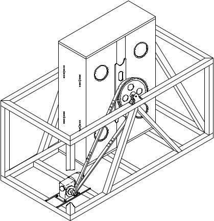
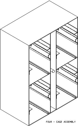
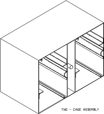
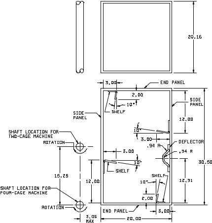
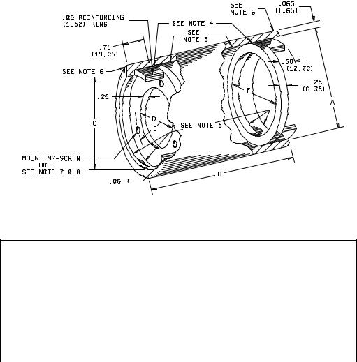
2.APPARATUS. The random-drop test machine consists of an assembly of either two or four steel cages as shown on figure 203-2, with provisions for rotation about a common axis. The interior of each cage shall be as shown on figure 203-3. A typical 4-cage machine is shown on figure 203-1. Steel sleeves as shown on figure 203-4 shall be used to mount the specimen.
3.PROCEDURE. The specimen shall be rigidly mounted by the normal mounting means in the steel sleeve so that no part of the specimen, including terminals or external hardware of the component, will extend beyond the sleeve. When necessary, a suitable adapter may be used within the sleeve. End caps shall not be used on the sleeves. Through bolts may be employed as needed to mount the specimens in the sleeve. Only one sleeve shall be placed in each cage during test. The number of specimens mounted in each sleeve shall be limited only by the available space. Specimens shall be subjected to the random-drop test for a period of 45 minutes at a speed of four to six (4 – 6) revolutions per minute. The machine shall be rotated in the direction shown on figure 203-3.
4.MEASUREMENTS. Upon completion of the test, measurements shall be made as specified in the individual specification.
5.SUMMARY. The following detail shall be specified in the individual specification: a. Measurements after test (see 4).
METHOD 203C
8 February 2002
1 of 6
MIL-STD-202G
FIGURE 203-1. Typical assembly of four-cage random-drop-test machine.
METHOD 203C
8 February 2002
2
MIL-STD-202G
FIGURE 203-2. Cage assembly.
METHOD 203C
8 February 2002
3
MIL-STD-202G
FIGURE 203-2. Cage assembly - Continued.
METHOD 203C
8 February 2002
4
MIL-STD-202G
C
L
Inches |
mm |
Inches |
mm |
Inches |
mm |
.94 |
23.83 |
12.00 |
304.80 |
20.00 |
508.00 |
2.00 |
50.80 |
12.91 |
327.91 |
20.16 |
512.06 |
3.00 |
76.20 |
15.25 |
387.35 |
30.50 |
774.70 |
3.06 |
77.72 |
|
|
|
|
NOTES:
1.Unless otherwise specified, tolerances are ±.06 (1.52 mm) on decimals and ±0° 30' on angles.
2.Material for end and side panels shall be steel .0747 (1.90 mm) nominal thickness.
3.Material for shelves and deflectors shall be steel .083 (2.11 mm) nominal thickness.
FIGURE 203-3. Cage (interior).
METHOD 203C
8 February 2002
5
MIL-STD-202G
Dimensions
A |
B ±.06 (1.52) |
C ±.06 (1.52) |
D |
E (Rad) |
F ±.06 (1.52) |
|
|
|
|
|
|
|
|
3.870 |
4.03 |
3.75 |
2.220 |
7/ |
1.220 |
3.370 |
(98.30) |
(102.36) |
(95.25) |
(56.39) |
(30.99) |
(85.60) |
|
|
|
|
|
|
|
|
3.870 |
4.03 |
3.75 |
2.820 |
7/ |
1.580 |
3.370 |
(98.30) |
(102.36) |
(95.25) |
(71.63) |
(40.13) |
(85.60) |
|
|
|
|
|
|
|
|
4.870 |
5.03 |
4.75 |
3.820 |
8/ |
2.062 |
4.370 |
(123.70) |
(127.76) |
(120.65) |
(97.03) |
(52.37) |
(111.00) |
|
|
|
|
|
|
|
|
NOTES:
1.Metric equivalents are in parentheses.
2.Unless otherwise specified, tolerances are ±.005 (0.13 mm) for three place decimals, and ±.02 (0.51 mm) for two place decimals.
3.Material for sleeve and reinforcing rings shall be carbon steel, condition CWSR, grade MT1015 or 1015, conforming to ASTM A 519-96.
4.Material shall be hot-rolled steel strip, annealed condition, annealed finish, conforming to QQ-S-698.
5.Silver solder all around. Silver solder shall conform to class 1 of QQ-B-654.
6.End of cylinder to be spun-over after insertion of reinforcing ring.
7.Radius of 3 holes equally spaced.
8.Radius of 6 holes equally spaced.
FIGURE 203-4. Sleeve.
METHOD 203C
8 February 2002
6
MIL-STD-202G
METHOD 204D
VIBRATION, HIGH FREQUENCY
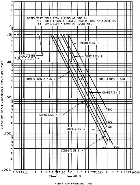
1.PURPOSE. The high frequency vibration test is performed for the purpose of determining the effect on component parts of vibration in the frequency ranges of 10 to 500 hertz (Hz), 10 to 2,000 Hz or 10 to 3,000 Hz, as may be encountered in aircraft, missiles, and tanks. The choice of test condition A, B, C, D, E, F, G, or H should be based on the frequency range and the vibration amplitude dictated by the applications of the component under consideration, and the state of the component part in relation to resistance-to-vibration damage.
2.PROCEDURE.
2.1Mounting. The specimens shall be mounted as specified. For specimens with attached brackets, one of the vibration test directions shall be parallel to the mounting surface of the bracket. Vibration input shall be monitored on the mounting fixture in the proximity of the support points of the specimen.
2.2Test condition A (10g peak). The specimens, while deenergized or operating under the load conditions specified, shall be subjected to the vibration amplitude, frequency range, and duration specified in 2.2.1, 2.2.2, and 2.2.3, respectively (see figure 204-1).
2.2.1Amplitude. The specimens shall be subjected to a simple harmonic motion having an amplitude of either 0.06-inch double amplitude (maximum total excursion) or 10 gravity units (g peak), whichever is less. The tolerance on vibration amplitude shall be ±10 percent.
2.2.2Frequency range. The vibration frequency shall be varied logarithmically between the approximate limits of 10 and 500 Hz (see 2.10), except that the procedure of method 201 of this standard may be applied during the 10 to 55 Hz band of the vibration frequency range.
2.2.3Sweep time and duration. The entire frequency range of 10 to 500 Hz and return to 10 Hz shall be traversed in 15 minutes. This cycle shall be performed 12 times in each of three mutually perpendicular directions (total of 36 times), so that the motion shall be applied for a total period of approximately 9 hours. Interruptions are permitted provided the requirements for rate of change and test duration are met. Completion of cycling within any separate band is permissible before going to the next band. When the procedure of method 201 of this standard is used for the 10 to 55 Hz band, the duration of this portion shall be the same as the duration for this band using logarithmic cycling (approximately 1-1/3 hours in each of three mutually perpendicular directions).
2.3 Test condition B (15g peak). The specimens, while deenergized or operating under the load conditions specified, shall be subjected to the vibration amplitude, frequency range, and duration specified in 2.3.1, 2.3.2, and 2.3.3, respectively (see figure 204-1).
2.3.1Amplitude. The specimens shall be subjected to a simple harmonic motion having an amplitude of either 0.06-inch double amplitude (maximum total excursion) or 15g (peak), whichever is less. The tolerance on vibration amplitude shall be ±10 percent.
2.3.2Frequency range. The vibration frequency shall be varied logarithmically between the approximate limits of 10 to 2,000 Hz (see 2.10), except that the procedure of method 201 of this standard may be applied during the 10 to 55 Hz band of the vibration frequency range.
2.3.3Sweep time and duration. The entire frequency range of 10 to 2,000 Hz and return to 10 Hz shall be traversed in 20 minutes. This cycle shall be performed 12 times in each of three mutually perpendicular directions (total of 36 times), so that the motion shall be applied for a total period of approximately 12 hours. Interruptions are permitted provided the requirements for rate of change and test duration are met. Completion of cycling within any separate band is permissible before going to the next band. When the procedure of method 201 of this standard is used for the 10 to 55 Hz band, the duration of this portion shall be the same as the duration for this band using logarithmic cycling (approximately 1-1/3 hours in each of three mutually perpendicular directions).
METHOD 204D 1 April 1980
1 of 6
MIL-STD-202G
G = .0512f2DA (f = frequency in hertz, DA = double amplitude in inches.)
FIGURE 204-1. Vibration-test curves.
METHOD 204D
1 April 1980
2
MIL-STD-202G
2.4 Test condition C (10g peak). The specimens, while de-energized or operating under the load conditions specified, shall be subjected to the vibration amplitude and frequency range shown on figure 204-1. The tolerance on vibration amplitude shall be ±10 percent.
2.4.1Part 1. The specimens shall be tested in accordance with method 201 of this standard for 6 hours; 2 hours in each of three mutually perpendicular directions.
2.4.2Part 2. The specimens shall be subjected to a simple harmonic motion having an amplitude varied to maintain a constant peak acceleration of 10g (peak), the frequency being varied logarithmically between the approximate limits of 55 and 2,000 Hz (see 2.10). The entire frequency range of 55 to 2,000 Hz (no return sweep) shall be traversed in 35 ±5 minutes, except that in the vicinity of what appears to be resonance, and in order to facilitate the establishment of a resonant frequency, the above rate may be decreased. If resonance is detected, specimens shall be vibrated for 5 minutes at each critical resonant frequency observed. This procedure shall be performed in each of three mutually perpendicular directions. Interruptions are permitted provided the requirements for rate of change and test duration are met.
2.4.3Resonance. A critical resonant frequency is that frequency at which any point on the specimen is observed to have a maximum amplitude more than twice that of the support points. When specified, resonant frequencies shall be determined either by monitoring parameters such as contact opening, or by use of resonance-detecting instrumentation.
2.5 Test condition D (20g peak). The specimens, while de-energized or operating under the load conditions specified, shall be subjected to the vibration amplitude, frequency, range, and duration specified in 2.5.1, 2.5.2, and 2.5.3, respectively (see fig. 204-1).
2.5.1Amplitude. The specimens shall be subjected to a simple harmonic motion having an amplitude of either 0.06-inch double amplitude (maximum total excursion) or 20g (peak), whichever is less. The tolerance on vibration amplitude shall be ±10 percent.
2.5.2Frequency range. The vibration frequency shall be varied logarithmically between the approximate limits of 10 to 2,000 Hz (see 2.10), except that the procedure of method 201 of this standard may be applied during the 10 to 55 Hz band of the vibration frequency range.
2.5.3Sweep time and duration. The entire frequency range of 10 to 2,000 Hz and return to 10 Hz shall be traversed in 20 minutes. This cycle shall be performed 12 times in each of three mutually perpendicular directions (total of 36 times), so that the motion shall be applied for a total period of approximately 12 hours. Interruptions are permitted provided the requirements for rate of change and test duration are met. Completion of cycling within any separate band is permissible before going to the next band. When the procedure of method 201 of this standard is used for the 10 to 55 Hz band, the duration of this portion shall be the same as the duration for this band using logarithmic cycling (approximately 1-1/3 hours in each of three mutually perpendicular directions).
2.6 Test condition E (50g peak). The specimens, while de-energized or operating under the load conditions specified, shall be subjected to the vibration amplitude, frequency, range, and duration specified in 2.6.1, 2.6.2, and 2.6.3, respectively (see figure 204-1).
2.6.1Amplitude. The specimens shall be subjected to a simple harmonic motion having an amplitude of either 0.06-inch double amplitude (maximum total excursion) or 50g (peak), whichever is less. The tolerance on vibration amplitude shall be ±10 percent.
2.6.2Frequency range. The vibration frequency shall be varied logarithmically between the approximate limits of 10 and 2,000 Hz (see 2.10), except that the procedure of method 201 of this standard may be applied during the 10 to 55 Hz band of the vibration frequency range.
METHOD 204D
1 April 1980
3
MIL-STD-202G
2.6.3 Sweep time and duration. The entire frequency range of 10 to 2,000 Hz and return to 10 Hz shall be traversed in 20 minutes. This cycle shall be performed 12 times in each of three mutually perpendicular directions (total of 36 times), so that the motion shall be applied for a total period of approximately 12 hours. Interruptions are permitted provided the requirements for rate of change and test duration are met. Completion of cycling within any separate band is permissible before going to the next band. When the procedure of method 201 of this standard is used for the 10 to 55 Hz band, the duration of this portion shall be the same as the duration for this band using logarithmic cycling (approximately 1-1/3 hours in each of three mutually perpendicular directions).
2.7 Test condition F (20g peak). The specimens, while de-energized or operating under the load conditions specified, shall be subjected to the vibration amplitude, frequency range, and duration specified in 2.7.1, 2.7.2, and 2.7.3, respectively (see figure 204-1).
2.7.1Amplitude. The specimens shall be subjected to a simple harmonic motion having an amplitude of either 0.06-inch double amplitude (maximum total excursion) or 20g (peak), whichever is less. The tolerance on vibration amplitude shall be ±10 percent.
2.7.2Frequency range. The vibration frequency shall be varied logarithmically between the limits of 10 and 3,000 Hz (see 2.10), except that the procedure of method 201 of this standard may be applied during the 10 to 55 Hz band of the vibration frequency range.
2.7.3Sweep time and duration. The entire frequency range of 10 to 3,000 Hz and return to 10 Hz shall be traversed in 20 minutes. This cycle shall be performed 12 times in each of three mutually perpendicular directions (total of 36 times), so that the motion shall be applied for a total period of approximately 12 hours. Interruptions are permitted provided the requirements for rate of change and test duration are met. Completion of cycling within any separate band is permissible before going to the next band. When the procedure of method 201 of this standard is used for the 10 to 55 Hz band, the duration of this portion shall be the same as the duration for this band using logarithmic cycling (approximately) 1-1/3 hours in each of three mutually perpendicular directions.
2.8 Test condition G (30g peak). The specimens, while deenergized or operating under the load conditions specified, shall be subjected to the vibration amplitude, frequency range, and duration specified in 2.8.1, 2.8.2, and 2.8.3, respectively (see figure 204-1).
2.8.1Amplitude. The specimens shall be subjected to a simple harmonic motion having an amplitude of either 0.06-inch double amplitude (maximum total excursion) or 30g (peak), whichever is less. The tolerance on vibration amplitude shall be ±10 percent.
2.8.2Frequency range. The vibration frequency shall be varied logarithmically between the limits of 10 and 2,000 Hz (see 2.10), except that the procedure of method 201 of this standard may be applied during the 10 to 55 Hz band of the vibration frequency range.
2.8.3Sweep time and duration. The entire frequency range of 10 to 2,000 Hz and return to 10 Hz shall be traversed in 20 minutes. This cycle shall be performed 12 times in each of three mutually perpendicular directions (total of 36 times), so that the motion shall be applied for a total period of approximately 12 hours. Interruptions are permitted provided the requirements for rate of change and test duration are met. Completion of cycling within any separate band is permissible before going to the next band. When the procedure of method 201 of this standard is used for the 10 to 55 Hz band, the duration of this portion shall be the same as the duration for this band using logarithmic cycling (approximately) 1-1/3 hours in each of three mutually perpendicular directions.
METHOD 204D
1 April 1980
4