

БЭМЗ полищук доки / 2020 / А2000 минск / Стандарт MIL-STD-202G
.pdfMIL-STD-202G
3.1.1.2 Mounting. The specimen to be tested shall be mounted in the test chamber in such a manner that normal electrical operation is possible and so that the mechanical controls may be operated through the pressure seals from the exterior of the chamber. All external covers of the test specimen shall be removed or opened to insure adequate circulation of the explosive mixture. The test specimen shall then be operated to determine that it is functioning properly and to observe the location of any sparking or high temperature spots that may constitute potential explosion hazards.
3.1.2 Loading. Applicable mechanical and electrical loads applied to the specimen shall be as specified in the individual specification. Proper precaution shall be taken to duplicate the normal load in respect to torque, voltage, current, inductive reactance, etc. In all instances it shall be considered preferable to operate the specimen as it normally functions during service use.
3.2Test execution. The following provides the procedural steps for execution of the explosive atmosphere test;
a.With the test item installed, the test chamber shall be sealed and the test item and chamber inner walls stabilized to 71°C ±3°C (160°F ±5°F), or to a lower temperature as specified, if the specimen is designed to operate at a lower temperature.
b.Adjust the chamber air pressure to simulate the desired test altitude (see 3.3) plus an additional 10,000 feet to allow for introducing, vaporizing, and mixing the fuel with the air as described in 2.3.
c.Slowly introduce the required volume of n-hexane into the test chamber.
d.Circulate the test atmosphere and continue to reduce the simulated chamber altitude for at least three minutes to allow for complete vaporization of fuel and the development of a homogeneous mixture.
e.At a pressure equivalent to 5,000 feet (1525 meters) above the test altitude, verify the potential explosiveness of the fuel-air vapor by attempting to ignite a sample of the mixture taken from the test chamber by using a spark-gap device or glow plug ignition source with sufficient energy to ignite a 3.82 percent hexane mixture. If ignition does not occur, purge the chamber of the fuel vapor and repeat steps a through e. (An alternative method of determining the explosive characteristics of the vapor is by using a calibrated explosive gas meter that verifies the degree of explosiveness and the concentration of the fuel-air mixture.)
f.Operate the test specimen and continue operation through step g. Make and break electrical contacts as frequently and reasonably possible.
g.If no explosion occurs as a result of operation of the test specimen, slowly reduce the simulated chamber altitude to 5,000 feet (1525 meters) below the test altitude (at a rate no faster than 330 feet (100 meters) per minute by bleeding air into the chamber). Perform one last operational check and switch off power to the test specimen.
h.If no explosion has occurred as the result of operation of the test specimen by the time the simulated altitude has reached 5,000 feet (1525 meters) below the test altitude, verify the potential explosiveness of the airvapor mixture as in step e. If ignition does not occur with the sample, purge the chamber of the fuel vapor, and repeat the test from step a.
i.Repeat steps b through h for the required test altitudes (see 3.3).
3.3Test altitudes. Unless otherwise specified, the test shall be accomplished at simulated test altitudes of local ground level to 5,000 feet, 20,000 feet, and 40,000 feet. However, if an explosion occurs at an altitude of less than 40,000 feet, further testing shall be discontinued.
METHOD 109C
8 February 2002
3
MIL-STD-202G
4.SUMMARY. The following details are to be specified in the individual specification.
a.Fuel, if other than that specified and all specific details associated with the fuel (see 2.2).
b.Mechanical and electrical load (see 3.1.2).
c.Chamber temperature condition, if lower than 71°C ±3°C (160°F ±5°F) (see 3.2 a).
d.Test altitudes, if other than those specified (see 3.3).
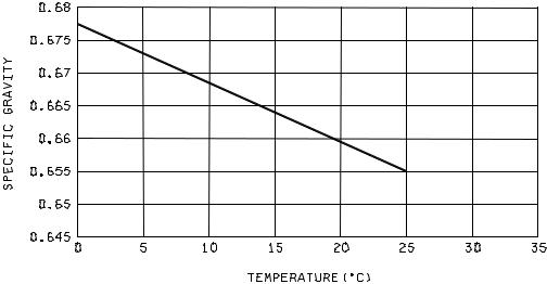
FIGURE 109-1. Specific gravity of n-hexane
METHOD 109C
8 February 2002
4
MIL-STD-202G
METHOD 110A
SAND AND DUST
1.PURPOSE. The dust test is used during the development, test, and evaluation of equipment to ascertain their ability to resist the effects of a dry dust (fine sand) laden atmosphere. This test simulates the effect of sharp edged dust (fine sand) particles, up to 150 microns in size, which may penetrate into cracks, crevices, bearings, and joints, and cause a variety of damage such as fouling moving parts, making relays inoperative, forming electrically conductive bridges with resulting "shorts" and acting as a nucleus for the collection of water vapor, and hence a source of possible corrosion and malfunction of equipment. This test is applicable to all mechanical, electrical, electronic, electrochemical, and electromechanical devices for which exposure to the effects of a dry dust (fine sand) laden atmosphere is anticipated.
2.APPARATUS. The test facility shall consist of a chamber and accessories to control dust concentration, velocity, temperature, and humidity of dust-laden air. In order to provide adequate circulation of the dust laden air, no more than 50 percent of the cross-sectional area (normal to air flow) and 30 percent of the volume of the chamber shall be occupied by the test item(s). The chamber shall be provided with a suitable means of maintaining and verifying the dust concentration in circulation. A minimum acceptable means for doing this is by use of a properly calibrated smoke meter and standard light source. The dust-laden air shall be introduced into the test space in such a manner as to allow it to become approximately laminar in flow before it strikes the test item.
2.1 Dust requirements. The dust used in this test shall be a fine sand (97-99% by weight SiO2) of angular structure, and shall have the following size distribution as determined by weight, using the
U.S. Standard Sieve Series.
a.100 percent of this dust shall pass through a 100-mesh screen.
b.98 ±2 percent of the dust shall pass through a 140-mesh screen.
c.90 ±2 percent of the dust shall pass through a 200-mesh screen.
d.75 ±2 percent of the dust shall pass through a 325-mesh screen.
"140-mesh silica flour" as produced by the Ottawa Silica Company, Ottawa, Illinois, or equal, is satisfactory for use in the performance of these tests.
3. PROCEDURE. Place the test item in the chamber, positioned as near the center of the chamber as practicable. If more than one item is being tested, there shall be a minimum clearance of 4 inches between surfaces of test items or any other material or object capable of furnishing protection. Also, no surface of the test item shall be closer than 4 inches from any wall of the test chamber. Orient the item so as to expose the most critical or vulnerable parts to the dust stream. The test item orientation may be changed during the test if so required by the component specification.
Step 1 - Set the chamber controls to maintain an internal chamber temperature of 23°C (73°F) and a relative humidity of less than 22 percent. Adjust the air velocity to 1,750 ±250 feet per minute. Adjust the dust feeder to control the dust concentration at 0.3 ±0.2 grams per cubic foot. With test item nonoperating, maintain these conditions for 6 hours.
Step 2 - Stop the dust feed and reduce the air velocity to 300 ±200 feet per minute. Raise the internal chamber air temperature to 63°C (145°F) and adjust humidity control to maintain a relative humidity of less than 10 percent. Hold these conditions for 16 hours.
METHOD 110A 16 April 1973
1 of 2
|
|
MIL-STD-202G |
Step 3 |
- |
While holding chamber temperature at 63°C (145°F) adjust the air velocity to 1,750 ±250 fpm, |
|
|
maintain a relative humidity of less than 10 percent. Adjust the dust feeder to control the dust |
|
|
concentration at 0.3 ±0.2 grams per cubic foot. With the test item nonoperating, maintain these |
|
|
conditions for 6 hours. |
Step 4 |
- |
Turn off all chamber controls and allow the test item to return to standard ambient conditions. |
|
|
Remove accumulated dust from the test item by brushing, wiping, or shaking, care being taken to |
|
|
avoid introduction of additional dust into the test item. Under no circumstances, shall dust be |
|
|
removed by either air blast or vacuum cleaning. |
NOTE: |
|
1. This test specimen may be operating during either or both of the 6-hour test periods (step 1 or 3) |
|
|
if so required by the component specification. |
2.When the component specifications reference test conditions A, B, or C of the previous version of this test method, steps 1 through 4 of this test will be used unless otherwise specified.
4.SUMMARY. The following details are to be specified in the component specification.
a.Change in orientation during test, if required.
b.Whether component is to operate during test and length of time required for operation and measurements.
c.Whether the second 6-hour test at 63°C (145°F) shall be performed immediately after reaching stabilization in step 2.
METHOD 110A
16 April 1973
2
MIL-STD-202G
METHOD 111A
FLAMMABILITY (EXTERNAL FLAME)
1.PURPOSE. This test is performed for the purpose of determining the flammability of a part exposed to an external flame. Flammability is defined as the ability of a part to support combustion. This can be determined by the following: the time it takes for a part to become self-extinguishing after application of a flame; that the part does not support violent burning; that exposure of a part to a flame does not result in an explosive-type fire; or that spreading of surface burning on larger parts is deterred. The principal factors which affect the results of an external flame test are -- the heat of the flame at the point of impingement; the size of the flame; the time of exposure to the flame; the volume of the part and other heat-sink effects; the presence of circulating materials and surfaces of the parts.
2.APPARATUS.
2.1Test chamber. An enclosure protected from air currents, but provided with means for venting fumes and admitting an adequate supply of fresh air at the bottom, shall be used. A standard chemistry hood with the exhaust fan turned off, or a metal box about 2 feet wide by 3 feet high and 2 feet deep, with a removable front, a viewing window, and holes for air intake and venting of fumes, is satisfactory. Adequate safety precautions should be taken to protect personnel from possible explosion of the test specimens.
2.2Mounting apparatus. Within the test chamber, a support stand with suitable adjustable vertical brackets or other mounting clamps shall be used to hold the specimens at the specified distance and position (see 3) with respect to the applied flame. Mounting clamps, in order not to act as heat sinks, shall be thermally insulated from the specimens. The flame shall not impinge on the clamp(s) or other devices which hold the specimens.
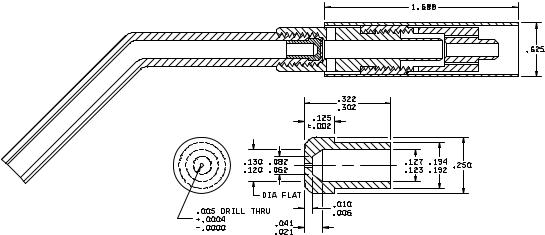
2.3Propane torch. A propane torch, having a nozzle assembly conforming to Model TX-1 of "Bernzomatic Corporation", or equal, shall be the source of the flame. "Cracked" propane gas shall be used as the fuel. A suggested torch assembly is shown on figure 111-1, Burner head.
2.4Timing device. A timing device, which can indicate time in seconds, shall be used to determine the time of application of the flame and the time of burning of visible flame on the specimen.
3.PROCEDURE. The specimen shall be mounted in the test chamber (see 2.1) with the mounting apparatus therein (see 2.2) and at the distance and position specified. The torch shall be placed so that the axis of the flame is in the vertical direction, unless otherwise specified in the individual specification. When the torch is ignited, and after the flame is stable, the flow of gas through the nozzle of the torch (see 2.3) shall be adjusted so that the inner-cone length is 1/2 inch between the inner-cone tip and a point in the plane of the nozzle rim. The specimen shall be placed so that the point of impingement of the flame on the specimen is 1-1/2 inches from the nozzle rim along the flame axis. The point of impingement of the flame shall be as specified in the individual specification. The flame shall be applied to the specimen for a period of 15 seconds unless specified in the individual specification, as determined by the timing device (see 2.4), and then removed. Upon removal of the applied flame, the time of burning of visible flame on the specimen, as determined by the timing device, shall be recorded. The recorded time shall then be compared with the allowable time specified in the individual specification. Any violent burning of the specimen or explosive-type fire shall be recorded.
4.CLEANING. In order to clearly observe the burned area; carbon from the propane gas may be removed by brushing or buffing the specimen.
5.MEASUREMENTS. Upon completion of the test, measurements shall be made as specified in the individual specification.
METHOD 111A 16 April 1973
1 of 5
MIL-STD-202G
6.SUMMARY. The following details are to be specified in the individual specification:
a.Direction of axis of flame, if other than vertical (see 3).
b.Point of impingement of applied flame (see 3).
c.Time of application of flame, if other than 15 seconds (see 3).
d.Allowable time for burning of visible flame on specimen (see 3).
e.Measurements after test (see 5).
METHOD 111A
16 April 1973
2
MIL-STD-202G
Inches |
mm |
Inches |
mm |
.0004 |
0.01 |
.125 |
3.18 |
.002 |
0.05 |
.127 |
3.23 |
.005 |
0.13 |
.130 |
3.30 |
.006 |
0.15 |
.192 |
4.88 |
.010 |
0.25 |
.194 |
4.93 |
.021 |
0.53 |
.250 |
6.35 |
.041 |
1.04 |
.302 |
7.67 |
.062 |
1.57 |
.322 |
8.18 |
.082 |
2.08 |
.625 |
15.18 |
.120 |
3.05 |
1.688 |
42.88 |
.123 |
3.12 |
|
|
MATERIAL: BRASS
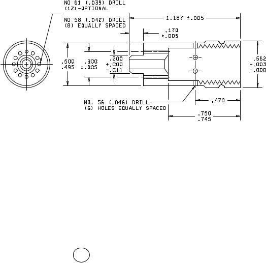
FIGURE 111-1. Burner head.
METHOD 111A
16 April 1973
3
MIL-STD-202G
Inches |
mm |
Inches |
mm |
.003 |
0.08 |
.300 |
7.62 |
.005 |
0.13 |
.470 |
11.94 |
.011 |
0.28 |
.495 |
12.57 |
.039 |
0.99 |
.500 |
12.70 |
.042 |
1.07 |
.562 |
14.27 |
.046 |
1.17 |
.745 |
18.92 |
.170 |
4.32 |
.750 |
19.05 |
.200 |
5.08 |
1.187 |
30.15 |
MATERIAL: BRASS
2
BODY-BURNER
FIGURE 111-1. Burner head - Continued.
METHOD 111A
16 April 1973
4
MIL-STD-202G
Inches |
mm |
Inches |
mm |
.002 |
0.05 |
.370 |
9.40 |
.005 |
0.13 |
.375 |
9.53 |
.081 |
2.06 |
.395 |
10.03 |
.090 |
2.29 |
.405 |
10.29 |
.095 |
2.41 |
.430 |
10.92 |
.156 |
3.96 |
.433 |
11.00 |
.187 |
4.75 |
.443 |
11.25 |
.198 |
5.03 |
.500 |
12.70 |
.202 |
5.13 |
.715 |
18.16 |
.250 |
6.35 |
.720 |
18.29 |
.360 |
9.14 |
1.500 |
38.10 |
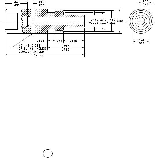
MATERIAL: BRASS
3
BASE-BURNER
FIGURE 111-1. Burner head - Continued.
METHOD 111A
16 April 1973
5