

БЭМЗ полищук доки / 2020 / А2000 минск / Стандарт MIL-STD-202G
.pdfMIL-STD-202G
3.2 Optional exposure procedure for the third group. The test specimens shall be located on a test surface of known area which is located 6 ±1 inches (15 ±2.5 centimeters) below a spray nozzle which discharges .16 ±.005 gpm (0.62 ±0.02 liters per minute) of solution per in2(6.5 square centimeters) of surface area at a pressure of 20 ±5 lbs/in2 (138 ±34 kilopascal). The solvent shall be held at a temperature range of 63°C to 70°C. The specimens shall be subjected to this spray for a period of 10 minutes. After completion of the spray exposure, the specimens shall be thoroughly rinsed in water and all surfaces air-blown dry and inspected in accordance with 4.1 and 4.2 to determine the extent, if any, of deterioration that has occurred. If this optional procedure is specified, brushing of the samples in the third group is not required. If a conflict arises from the use of the spray option, the brush method of 3.1d shall be used as the referee procedure. The measurements shown in parentheses are not exact equivalents and are shown for convenience only.
3.3 Immersion test for components with marking protected by a sleeve material. Components with a protective sleeve shall be divided into three groups as specified in 3, and each group shall be subjected to testing using the solution defined for that group. Each solution shall be maintained at a temperature of 25°C ±5°C, except the solution in 2.1d shall be maintained at a temperature of 63°C to 70°C. The specimens shall be completely immersed for 3 minutes +.5, -0 minutes in the specified solution contained in the vessel specified in 2.2. Immediately following immersion, each specimen shall be tested as follows: The bristle portion of the brush specified in 2.3 shall be dipped in the solution until wetted and the specimen shall be brushed with normal hand pressure (approximately 2 to 3 ounce force applied normal to the surface) for ten strokes on the sleeve directly above the area of the marking. Immediately after brushing, the procedure shall be repeated two more times for a total of three immersions followed by brushing. The brush stroke shall be directed in a forward direction across the sleeve area above the marking. After completion of the third immersion and brushing, the specimens shall be air-blown dry. The specimens shall be inspected in accordance with 4.1 and 4.2 to determine the extent, if any, of deterioration that has occurred, including the sleeve.
3.4 Open construction parts and parts not intended for PCB mounting. Parts of open construction which are susceptible to internal damage by immersion in solvents and parts not intended for mounting on printed circuit boards, shall be divided into three groups as specified in 3, and each group shall be subjected to testing using the solution defined for that group. Each solution shall be maintained at a temperature of 25°C ±5°C, except for the solution in 2.1d, which shall be maintained at a temperature range of 63°C to 70°C, and shall be contained in the vessel specified in 2.2. Each group shall be tested as follows: The bristle portion of the brush specified in 2.3 shall be immersed in the respective solution for each group until wetted. The marking area of the specimen to be tested shall then be immediately brushed with normal hand pressure (approximately 2 to 3 ounce force applied normal to the surface) for ten strokes on the portion of the specimen where marking has been applied (test area not to exceed onehalf inch square). The brush stroke shall be directed in a forward direction across the marked surface. This test shall be repeated twice for a total of three times for each specimen. The specimens shall then be inspected in accordance with 4.1 and 4.2 to determine the extent of deterioration, if any.
4. EXAMINATION AND MEASUREMENTS
4.1Marking resistance to solvents. After subjection to the test, any specified markings which are missing in whole or in part, faded, smeared, blurred, or shifted (dislodged) to the extent that they cannot be readily identified from a distance of at least 6 inches with normal room lighting without the aid of magnification or with a viewer having a magnification no greater than 3X shall constitute failure.
4.2Component protective coating, encapsulation material and sleeve material resistance. After subjection to the test, the specimen shall be examined for cracks, separations, crazing, swelling, softening, and degradation of body material, end caps and seals if present, or any other damage or degradation that has occurred due to solvent exposure and which effects the mechanical integrity or reliability shall constitute a failure. The examination shall be made with a viewer having a magnification of 10X maximum.
METHOD 215K
8 February 2002
3
MIL-STD-202G
5.SUMMARY. The following details are to be specified in the individual specification:
a.The number of specimens to be tested.
b.Optional procedure for the third group allowed (see 3.2).
TABLE I. Summary table for resistance to solvents.
Solvent 1 |
Solvent 2 |
Solvent 3 |
Solvent 4 |
1 part (by volume) of isopropyl |
This solvent has |
Terpene defluxer |
42 parts (by volume) of |
alcohol (ACS) |
been deleted. |
|
water |
reagent grade or TT-I-735, |
|
|
1 part (by volume) of |
grade A or B and 3 parts (by |
|
|
propylene glycol |
volume) of mineral spirits per |
|
|
monomethyl ether |
Mil-Prf-680, type I, |
|
|
1 part (by volume) of |
or three parts (by volume) of a |
|
|
monoethanolamine |
mixture of 80% (by volume) of |
|
|
|
kerosene and 20% |
|
|
|
(by volume) ethylbenzene. |
|
|
|
Immersion 3 +.5, -0 minutes, |
|
Immersion 3 +.5, -0 |
Immersion 3 +.5, -0 |
25°C ±5°C |
|
minutes, 25°C, ±5°C |
minutes, 63°C to 70°C |
Brush 10 strokes (wet bristle) |
|
Brush 10 strokes (wet |
Brush 10 strokes (wet |
2 to 3 oz. |
|
bristle) 2 to 3 oz. |
bristle) 2 to 3 oz. |
|
|
|
|
Immersion 3 +.5, -0 minutes, |
|
Immersion 3 +.5, -0 |
Immersion 3 +.5, -0 |
25°C ±5°C. |
|
minutes, 25°C ±5°C. |
minutes, 63°C to 70°C. |
Brush 10 strokes (wet bristle) |
|
Brush 10 strokes (wet |
Brush 10 strokes (wet |
2 to 3 oz. |
|
bristle) 2 to 3 oz. |
bristle) 2 to 3 oz. |
|
|
|
|
Immersion 3 +.5, -0 minutes, |
|
Immersion 3 +.5, -0 |
Immersion 3 +.5, -0 |
25°C ±5°C. |
|
minutes, 25°C ±5°C. |
minutes, 63°C to 70°C. |
Brush 10 strokes (wet bristle) |
|
Brush 10 strokes (wet |
Brush 10 strokes (wet |
2 to 3 oz. |
|
bristle) 2 to 3 oz. |
bristle) 2 to 3 oz. |
|
|
|
|
|
|
Rinse in water |
Rinse in water. |
Air blow dry. |
|
Air blow dry |
Air blow dry. |
Inspect at 3X maximum for |
|
Inspect at 3X maximum |
Inspect at 3X maximum |
marking. |
|
for marking. |
for marking. |
Inspect at 10X maximum for |
|
Inspect at 10X maximum |
Inspect at 10X maximum |
part damage. |
|
for part damage. |
for part damage. |
METHOD 215K |
|
|
|
8 February 2002 |
|
|
|
4
MIL-STD-202G
METHOD 216
RESISTANCE TO SOLDER WAVE HEAT
NOTICE
Method 216 has been canceled effective 16 April 1973. Use the test conditions in method 210 in lieu of the test conditions of method 216. Use the table below for the applicable cross reference.
When method 216 |
Use method 210 |
is specified |
|
|
|
Test condition A |
Test condition C |
Test condition B |
Test condition D |
Test condition C |
Test condition E |
|
|
METHOD 216
16 April 1973
1 of 1
MIL-STD-202G
METHOD 217A
PARTICLE IMPACT NOISE DETECTION (PIND)
1.PURPOSE. The purpose of this test is to detect the presence of free moving particulate contaminants within sealed cavity devices. This test method is specifically directed toward relays and other devices where internal mechanism noise makes rejection exclusively by threshold level impractical. This test method also may be used prior to final sealing in the manufacturing sequence as a means of eliminating loose particles from the interior of the device.
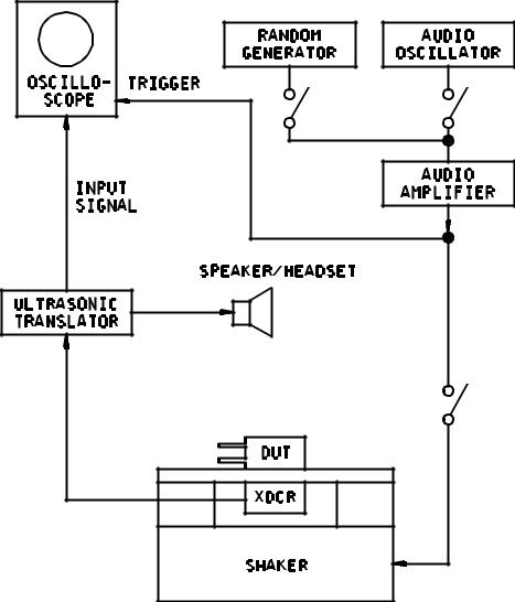
2.APPARATUS. The basic PIND system is comprised of the following components: (Substitutions of individual units or complete system may be made providing the test requirements of paragraph 3 are met.)
a.Vibration power source consisting of electrical driver audio oscillator and low frequency audio amplifier.
b.Ultrasonic sound detection system consisting of a crystal transducer with frequency response of 36 kHz - 44 kHz and associated translator preamplifier capable of converting transducer output to 20 Hz - 5 kHz.
c.Small vibration shaker or two shakers coupled together.
d.Oscilloscope, single beam, with 100 kHz minimum bandwidth capable of external synchronization.
e.Audio speaker or headset.
f.Test fixture to adapt transducer to shaker head and isolate it from external noise sources.
g.Holding fixture designed to hold flat surface of unit under test firmly against the sensing surface of the transducer.
h.Shock test fixture (see figure 217-3).
i.Calibration unit per 3.1c.
j.Random vibration generator.
3.PROCEDURE. Test equipment shall be assembled as shown on figure 217-1. System calibration, as defined in 3.1b, shall be performed at the following intervals:
a.Each time equipment is turned on.
b.Each change of operators.
c.At initial and completion of test for each group of devices.
d.Every four hours throughout testing.
Whenever system sensitivity is found to be below specified minimum, all units tested subsequent to previous acceptable calibration shall be retested. Units rejected for particle noise shall not be reworked or retested for the purpose of acceptance. Units rejected for excessive mechanism noise may be retested for the purpose of eliminating the mechanism noise.
METHOD 217A
8 February 2002
1 of 6
MIL-STD-202G
3.1Calibration.
a.Each unit of test equipment subject to calibration shall be maintained in accordance with ANSI/NCSL Z540-1.
b.System calibration shall consist of verifying the proper oscilloscope pattern while calibration unit is being energized by the shaker head at the frequency and acceleration specified in 3.2. Calibration shall also include elimination of extraneous noise which interferes with proper performance of the test.
c.Test the system with a container (size approximately ½" (12.7 mm) X 1" (25.4 mm) X 1" (25.4 mm) or smaller) which contains a 60/40 solder ball with a diameter of 0.005’’. Listen to the audible sound and observe the oscilloscope response to the solder ball.
d.Test the system with a container (size approximately 1/2" (12.7 mm) X 1" (25.4 mm) X 1" (25.4 mm) or smaller) which contains no particle, and compare the audible sound and the oscilloscope response to the results of step c to insure that particles are detectable.
3.2Test setup. The area in which the PIND system is used shall be carefully selected to avoid external interference from electrical and mechanical noise which will decrease the effectiveness of the test.
a.Set audio oscillator to 27 ±1 Hz.
b.Adjust audio amplifier to produce 3-5g (.07" (1.78 mm) - .14" (3.56 mm) displacement) at shaker head.
c.Check mechanical and electrical systems to minimize background noise. Background noise shall not increase more than 3 dB when shaker is placed in operation (except shaker reversal noise) and total system noise shall not exceed 20 mV. Adjust oscilloscope trace to less than 4 divisions displacement and center shaker reversal noise as shown on figure 217-2a. No other noise spikes shall be detectable.
d.Adjust audio output to comfortable level.
e.With calibration unit mounted on shaker verify proper oscilloscope and system sensitivity to produce random noise spikes of 40 mV minimum (figure 217-2c).
3.3Test procedure.
3.3.1Degausing. Devices not incorporating permanent magnets and devices being tested prior to final magnetization shall be degaused prior to PIND testing.
3.3.2Lead protection. When a device incorporates relatively long and flexible leads, the leads shall be suitably restrained from striking the shaker/fixture or striking each other during test. Care shall be taken to prevent damage caused by resonance.
3.3.3Testing. Mount unit under test in the center of acoustic transducer with largest flat surface down (paragraph 4b). Energize shaker and monitor for visual and audible evidence of loose internal material as evidenced by nonperiodic noise spikes (figure 217-2c). A single burst of noise is cause for rejection whether or not the indication can be repeated.
Allow test to proceed for approximately 5 seconds. If no failure is detected, apply a random acceleration for 3 seconds maximum or 3 to 5 shock pulses (not to exceed the rating of the device) perpendicular to the axis of vibration (see figure 217-3). Monitor for 5 seconds then repeat random vibration or shocks and monitor for an additional 5 seconds (30 seconds maximum per axis).
METHOD 217A
8 February 2002
2
MIL-STD-202G
NOTE: If excessive mechanism noise occurs (figure 217-2d) such that particle noise would be undetectable, the following action may be taken to reduce the noise:
a.Reorient unit by rotation about the shaker axis.
b.Change shaker amplitude within the specified limits.
c.Tilt shaker axis off vertical in any direction (not exceeding 30°) to provide a gravitational side component to the shaker acceleration.
d.With approval of the procuring agency, a different test frequency may be established for a given device.
e.Cancel out periodic noise.
If no particle is detected rotate unit to another flat surface providing vibration in a different axis. Repeat above test for not to exceed 30 seconds. Units shall not be tested with terminals or other non-cavity portions of the assembly in contact with the transducer.
3.3.4Marking. If specified (see 4d), those units which successfully pass PIND test shall be marked "PIND" on any surface providing existing markings are not obscured.
3.3.5Failed units. Those units which exhibit either particle noise or excessive mechanism noise which cannot be eliminated as described in 3.3.3 shall be rejected from the lot.
4.SUMMARY. The following details are to be specified in the individual specification:
a.Test frequency and acceleration if other than specified.
b.Axes of vibration if other than specified.
c.Test duration if other than specified.
d.Test acceptance marking if specified.
e.Frequency and magnitude of random noise generator shall be specified.
METHOD 217A
8 February 2002
3
MIL-STD-202G
FIGURE 217-1. Typical test circuit.
METHOD 217A
8 February 2002
4
MIL-STD-202G
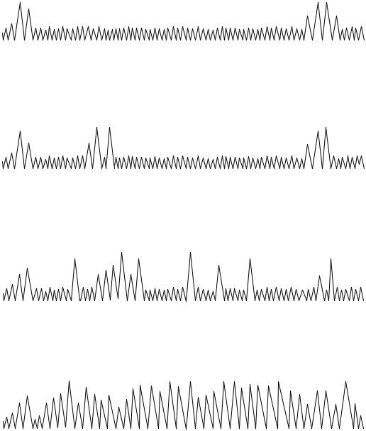
ACCEPTANCE CRITERIA: Each unit tested shall meet the acceptance.
SHAKER NOISE
Timebase adjusted to locate shaker reversal noise bursts at ends of oscilloscope trace. Test unit not mounted. a
INHERENT MECHANICAL NOISE
Synchronized spike may appear at different locations on time base for each unit under test. b
PARTICULATE NOISE
Non-synchronized spikes of any magnitude appear randomly and may disappear as test progresses. Unit is rejectable. c
EXCESSIVE MECHANICAL NOISE
Synchronized trace masks more than 50% of oscilloscope trace. Unit is rejectable. d
FIGURE 217-2. Representative oscilloscope traces.
METHOD 217A
8 February 2002
5
MIL-STD-202G
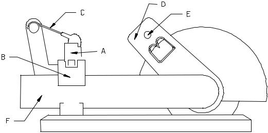
A. Unit under test.
B. Holding fixture.
C. Holding spring.
D. Angle indicator and adjustment.
E. Holding and dropping pin.
F. Dropping arm.
FIGURE 217-3. Shock test fixture.
METHOD 217A
8 February 2002
6