

БЭМЗ полищук доки / 2020 / А2000 минск / Стандарт MIL-STD-202G
.pdfMIL-STD-202G
Resistors
R1 - 35K 1/2W, 1% (see note 1) R2 - 27K 1/2W, 5%
R3 - 47K 1W, 5% R4 - 200K 1/2W, 5% R5 - 70K 1W, 5% R6 - 2.4K 1W, 5% R7 - 5K 1W
R8 - 500 1/2W, 5%
Capacitors
C1 - .0022 F, 600 VDCW (see note 1)
Miscellaneous
DS1 |
- NE-51 |
S1 |
- DPDT |
S2 |
- SPSTNC 125V 1 amp (push) |
V1 |
- JAN-5727/2D21W |
NOTES:
1.These values are to be chosen to obtain the desired time-duration for the applicable test condition (see 4.3). These particular values are applicable to 10 microseconds time-duration only.
FIGURE 310-1. Test-circuit A; monitor circuit for contact-opening and closing.
METHOD 310
20 January 1967
3
METHOD 310
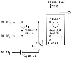
NOTE: The oscilloscope shall have an accuracy of ±3 percent or better on time base and have provision for external triggering.
FIGURE 310-2. Calibration circuit for test-circuit A.
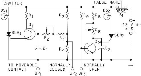
3.2 Test circuit B. The monitor-circuit shown on figure 310-3 permits detection of contact-chatter of closed contacts and false closure of open contacts, independently or simultaneously. The low contact-load levels (see 2.1.2) insure that there will be no arcing of the contacts during monitoring.
a.The chatter portion of figure 310-3, resistors R3 and R4 form a voltage divider with their junction at +2 volts. The closed contacts of the component under test, short-circuit R4 and place the base of transistor amplifier Q1 to ground potential. When the contacts under test "chatter" (open), resistor R4 is no longer shortcircuited and capacitor C1 starts to charge through R2 and R7 to +2 volts. The time necessary for C1 to charge to the correct bias-level is determined by the resistance of R2 and R7 and the capacitance value of C1. As transistor Q1 draws current through the gate of SCR1, the unit will fire and turn-on lamp DS1. Since in a silicon-controlled rectifier, the gate loses control after it is turned "on", the contacts can reclose at any
time thereafter without affecting the monitoring circuit. The time-delay, before turn-on, can be adjusted by varying R2 and selecting the capacitance value of C1. (For example: C1 = .002 F gives a 10-microsecond open-contact time.)
b.In the false-make portion of figure 310-3, transistor-amplifier Q2 is normally "on" with the gate of SCR2 being effectively held at ground potential by the low-output impedance of transistor Q2. When a "false-make" occurs, the base of Q2 transistor is grounded, turning Q2 "off". This allows the gate of the SCR2, which is
tied to the collector of transistor Q2, to rise to +12 volts. The rate of increase is determined by the value of C2 and R8. (For example: C2 = .002 F gives a 10-microsecond false-make time.) When the voltage reaches the gate turn-on level of SCR2, lamp DS2 will light, indicating a false closure of the open contacts.
METHOD 310
20 January 1967
4
MIL-STD-202G
c.When this circuit is being used to simultaneously monitor both the open and closed contacts of a double set of contacts:
(1)If DS1 "lights", it is an indication of contact chatter.
(2)If DS1 and DS2 "lights", it is an indication of false transfer or possible bridging, i.e., the movable contact of the open circuit "closes" but the closed circuit has not opened.
(3)If DS2 "lights", it is an indication of bridging.
d.Restoration of the circuit for an indication of failure is accomplished by the operation of S1.
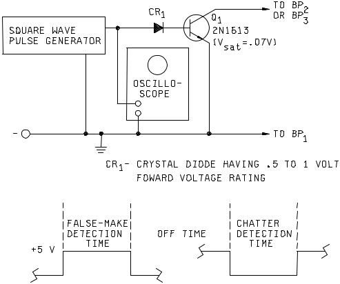
3.2.1 Calibration procedure for test-circuit B. The calibration-circuit shown on figure 310-4 may be used to calibrate the monitoring-circuit shown on figure 310-3 by using the following procedure:
a.Make the proper connections of the monitoring-circuit to the calibration-circuit.
(1)BP1 and BP2 for contact-chatter calibration.
(2)BP1 and BP3 for false contact-make calibration.
b.Select the appropriate 5 volt square-wave "pulse-polarity" and "pulse-width" to be furnished by the pulse generator and monitor the pulse on the oscilloscope, as follows:
(1)For contact-chatter calibration: Negative pulse.
(2)For false contact-make calibration: Positive pulse.
(3)Pulse width for either of the preceding (1) or (2) equal to the required detection time.
c.If DS1 or DS2 (as applicable) "lights", adjust R2 or R8 until the light is extinguished.
d.Slowly adjust R2 and R8 (as applicable) to the time-duration specified in the individual specification, as indicated by the first point at which DS1 or DS2 "lights".
METHOD 310
20 January 1967
5
MIL-STD-202G
C1, C2 |
- Choose for specified time (see note 1) |
R6 |
- 1,000 ohms 1/4W, 5% |
DS1, DS2 |
- No. 344 Lamp |
R7 - 100 ohms 1/4W, 5% |
|
R1 - 750 ohms 1/4W, 5% |
R8 |
- 200 ohms pot. |
|
R2 |
- 2,000 ohms pot. |
Q1, Q2 |
- 2N332A or equivalent |
R3, R5 |
- 10,000 ohms 1/4W, 5% |
SCR1, SCR2 |
- 2N1595 or equivalent |
R4 |
- 2,500 ohms 1/4W, 5% |
S1 |
- SPST NC Push |
NOTE:
1.Use .0022 F for 10 microsecond time-duration. Other time-duration will require larger capacitors.
FIGURE 310-3. Test-circuit B; monitor circuit for contact-chatter and false closures.
METHOD 310
20 January 1967
6
MIL-STD-202G
NOTES:
1.The square-wave pulse generator and oscilloscope shall have an accuracy of ±3 percent or better.
2.The ratio of off-time to detection-time shall be 10:1 or better.
FIGURE 310-4. Calibration circuit for test-circuit B.
METHOD 310
20 January 1967
7
MIL-STD-202G
4. PROCEDURE.
4.1Preparation. The monitor-circuits of figures 310-1 and 310-3 shall be calibrated, immediately prior to use, using the applicable calibration-circuit (see figures 310-2 and 310-4, respectively). The calibration-circuit shall then be disconnected from the monitoring-circuit.
4.2Points of connection. The contacts of the test-specimen being monitored shall be connected to points BP1 and BP2 for test circuit A for both contact-chatter and false-make contact conditions. For test circuit B, the points of connection shall be BP1 and BP2 for contact-chatter condition and to points BP1 and BP3 for false-make contact condition. The test specimen shall then be subjected to the shock, vibration, acceleration, or other environmental test during which this contact-chatter monitoring test method is to be used. If specified in the individual specification, test specimens having normally-closed contacts may be wired in series to monitor for opening of contacts, and those having normally-open contacts may be wired in parallel to monitor for closing of contacts. In this case, if contact opening or closing is indicated, it will then be necessary to reset each test specimen separately and monitor it individually to determine which one is defective.
4.3Test conditions. Test specimens shall be subjected to one of the following test conditions, as specified in the individual specification:
Test condition |
Time duration |
A |
10 microseconds |
B |
100 microseconds |
C |
1 millisecond |
D |
5 milliseconds |
E |
20 milliseconds |
5.SUMMARY. The following details are to be specified in the individual specification:
a.Test circuit letter (see 2.1, 3.1, and 3.2).
b.Test condition letter for maximum allowable time-duration of contact-opening or closing, as applicable (see 4.3).
c.Whether series-connection (of normally-closed contact test-specimens) or parallel-connection (of normallyopen contact test-specimens) may be allowed (see 4.2).
METHOD 310
20 January 1967
8
MIL-STD-202G
METHOD 311
LIFE, LOW LEVEL SWITCHING
1.PURPOSE. This test is conducted for the purpose of determining electrical contact reliability under low-level switching conditions in the environment in which the contacts operate. A low level switching circuit is one in which the voltage and stored energy are sufficiently small so that the resistance of a pair of contacts is not affected by electrical phenomena associated with the electrical current flow or the switching. Such a circuit is also one where the voltage or the current is too low to cause any physical change in the contacts; contact resistance can only be affected by changes in the contacts caused by mechanical action on the contacts. Electrical loads, which result in arcing across electrical contacts, affect contact surfaces in many ways, mostly favorable to reduction of contact resistance, since insulating films and small rough raised areas on the contact are burned away or melted down, to reform as a more even and larger contact surface. Under low-level conditions, the advantages, as well as the occasional disadvantages of this arcing will be absent. If low-level loads and intermediate or power loads are to be applied to different pairs of contacts on the same component part simultaneously, reliability of the low-level conditions can be impaired due to deposition of foreign materials resulting from vaporization surrounding the contacts operating at larger loads in the same enclosure or in an adjacent area, because of this fact, and because low-level contacts may develop films as a function of their environment, the contacts are tested in an environment similar to that in which they are used. This test in no way reflects the contact capability in the intermediate or "minimum" current area and shall not be considered as a substitute for testing in this area when specified.
2.APPARATUS.
2.1Test circuit. Monitoring of the contact resistance of each pair of contacts shall be accomplished on each cycle. A separate monitoring indicator shall be used for each pair of contacts. The apparatus, which cyclically operates the contacts, shall be capable of automatically cycling the contacts at the rate specified. The power source for the opencircuit voltage shall not exceed 30 millivolts dc maximum or peak ac at 10 milliamperes (mA) maximum. Open-circuit voltage is defined as the voltage that would appear at the contacts, when the circuit is energized and when the contacts are open. One means of generating this voltage is to pass a stable adjustable current through a lowohmage resistor (such as a shunt resistor for an ammeter). This means will provide the low impedance, low voltage, controllable, and well defined voltage source necessary. The current shall be adjusted so that the current through the pair of contacts, when closed is limited to 10 milliamperes, maximum.
2.2Monitoring apparatus. The monitoring apparatus shall be capable of indicating resistances greater than a particular value, as specified. Care should be exercised so as to minimize any loading effects by the monitoring apparatus such as current surges as a result of shunt capacitance of shield wire or instrumentation current to the monitoring indicator. During each closure, the contact potential shall be monitored for at least 50 percent of the time contacts are closed. The apparatus shall provide and record, either manually or automatically, the following information:
a.Number of contact closures with contact load applied.
b.If required, number of times the contacts have performed as specified prior to the first failure to perform as specified.
c.Number of times the contacts have failed to perform as specified, i.e., the number of "misses".
d.Sticking of contacts, when in the "open" condition, unless otherwise specified. Sticking of contacts shall be defined as failure to reach 90 percent of the open-circuit voltage.
3. PROCEDURE. Each pair of contacts shall be operated for the number of cycles specified at the specified cycling rate with the required test load (see 2) applied. The contact resistance shall be continuously monitored using the apparatus in 2.1 and 2.2.
METHOD 311
14 April 1969
1 of 2
MIL-STD-202G
4.SUMMARY. The following details are to be specified in the individual specification:
a.If applicable, specify environment, e.g., temperature, humidity, pressure, composition of atmosphere, and any other special environmental conditions (see 1).
b.Number of "misses" allowed which will be considered a failure (see 2).
c.Maximum contact resistance allowed (see 2.1).
d.If monitoring of contacts for sticking is not applicable (see 2.2).
e.Number of cycles of operation and cycling rate (see 3).
METHOD 311
14 April 1969
2
MIL-STD-202G
METHOD 312
INTERMEDIATE CURRENT SWITCHING
1.PURPOSE. This test is conducted for the purpose of determining the electrical contact reliability of such items as electromechanical relays, switches, etc., under intermediate current (formerly known as "minimum current") switching conditions under which the contacts operate. An intermediate current switching circuit is one in which there is insufficient voltage and stored energy to cause contact arcing during opening or closing of mating contacts, but which have sufficient energy to cause melting of the contact material. Normal arcing of contacts at rated load levels often act to burn off any oxide or other film on the contacts or provide localized melting at the point of contact, so that contact resistance does not rise drastically. Without this arcing of the contacts, oxides and other contaminant films can build up on contacts in component parts which have not been sealed adequately or which have contaminating materials and vapors trapped within the enclosure due to improper manufacturing techniques. Such contacts will develop unacceptably high contact resistance under intermediate current loads, unless the contact force and wipe are sufficiently heavy to overcome any effect of contamination. Intermediate current switching is the range in which a large percentage of loads occur. Therefore, it is extremely important that an intermediate current switching test be imposed on all electromechanical relays and switches, which are to be used in this range. Relays and switches, which pass both low level and full rated load tests, frequently fail when used in the intermediate current switching range.
2.PRECAUTIONS. Full rated load and low level life tests are not a substitute for the intermediate current switching test. Successful testing at low level and full rated loads in no way reflects the capability of the relay or switch at intermediate current loads. Statements or titles for component parts, such as "low level to full rated load" shall not be used in specifications, unless intermediate current switching capability has been demonstrated by the requirement for testing by this method.
CAUTION: A low-level run-in test is not equivalent to intermediate current testing and conversely intermediate current capability does not indicate low level capability.
3. APPARATUS.
3.1 Test circuit. Monitoring of the specified contact resistance of each pair of mating contacts shall be accomplished on each cycle. Each contact shall be monitored on each closure. The apparatus, which cyclically operates the contacts, shall be capable of automatically cycling the contacts at the rate specified. Resistive load voltage shall be applied to the contacts and shall be 3.0 V dc to 10.0 V dc at 100 ±10.0 milliamperes (mA) such as by means of a well regulated power supply which will provide the low voltage, controllable, and well defined voltage source. Voltage, when required to energize coils in order to actuate the contacts, shall be as specified. Both normally open and normally closed contacts of double-throw switching parts shall be tested. Multipole contacts shall be connected with all normally open pairs of contacts loaded and all normally closed pairs of contacts loaded.
3.2 Monitoring apparatus. The monitoring apparatus shall be capable of indicating resistances greater than a particular value specified. During each closure, the contact potential shall be monitored 10 milliseconds (ms) or more after the end of specified contact bounce. The apparatus shall provide and record either manually or automatically, the following information:
a.Number of contact closures with contact load applied.
b.If required, number of times contacts have performed as specified prior to failure to perform as specified.
c.Sticking of contacts, when intended to be in the "open" condition, unless otherwise specified. Sticking of contacts shall be defined as any failure of closed contacts to open as required during the cycling, or indication across such contacts of less than 90 percent of the applied open-circuit contact voltage.
METHOD 312
16 April 1973
1 of 2
MIL-STD-202G
4. PROCEDURE. Each pair of contacts shall be operated for 25,000 cycles (see note below) at the specified cycling rate. The duty cycle shall be approximately 50 percent "on" and 50 percent "off". The component parts shall be tested in a temperature chamber at the rated maximum ambient operating temperature with the required test load (see 3.1). When specified, the final half of the test cycles shall be tested at room ambient temperature. Each pair of contacts shall be individually monitored on each operation for failure-to-break (FTB) and for failure-to-make (FTM) the test load, using the apparatus in 3.1 and 3.2. FTB shall be defined as a voltage drop across the contacts of less than 90 percent of the applied voltage when the contacts are intended to be open. FTM shall be defined as a voltage drop across the contacts greater than 0.1 times the maximum allowable contact resistance (in ohms), when the contacts are intended to be closed. The voltage drop across the contacts shall be monitored for at least 50 percent of the time the contacts are closed and for at least 50 percent of the time the contacts are open, unless the monitoring apparatus can be demonstrated to be capable of settling to a stable reading in a shorter period of time. Any FTB or FTM shall either be recorded or shall automatically stop the actuating apparatus.
NOTE: Because the test is conducted for only 25,000 operations, it must not be inferred that the relays or switches, so tested, are suitable for only 25,000 operations in the intermediate current range. Quite the contrary, if the 25,000 operations test is passed satisfactorily, the relays or switches can be expected to be capable of switching intermediate current loads well beyond the full rated load life cycles specified.
5.SUMMARY. The following details are to be specified in the individual specification:
a.Maximum contact resistance allowed (see 3.1).
b.Coil energizing voltage (see 3.1).
c.Cycling rate (see 3.1).
d.Contact bounce, if applicable (see 3.2).
e.If monitoring of contacts for sticking is not applicable (see 3.2c).
f.Whether final half of cycles is to be tested at room ambient temperature (see 4).
g.Rated maximum operating ambient temperature (see 4).
METHOD 312
16 April 1973
2