

БЭМЗ полищук доки / 2020 / А2000 минск / Стандарт MIL-STD-202G
.pdfMIL-STD-202G
METHOD 103B
HUMIDITY (STEADY STATE)
1.PURPOSE. This test is performed to evaluate the properties of materials used in components as they are influenced by the absorption and diffusion of moisture and moisture vapor. This is an accelerated environmental test, accomplished by the continuous exposure of the specimen to high relative humidity at an elevated temperature. These conditions impose a vapor pressure on the material under test which constitutes the force behind the moisture igration and penetration. Hygroscopic materials are sensitive to moisture, and deteriorate rapidly under humid conditions. Absorption of moisture by many materials results in swelling, which destroys their functional utility, and causes loss of physical strength and changes in other important mechanical properties. Insulating materials that absorb moisture may suffer degradation of their electrical properties. This method, while not necessarily intended as a simulated tropical test, is of use in determining moisture absorption of insulating materials.
2.PROCEDURE.
2.1Conditioning. The specimens shall be conditioned in a dry oven at a temperature of 40° ±5°C for a period of 24 hours. At the end of this period, measurements shall be made as specified.
2.2Chamber. The chamber and accessories shall be constructed and arranged in such a manner as to avoid condensate dripping on the specimens under test, and such that the specimens shall be exposed to circulating air.
2.3Exposure. The specimens shall be placed in a chamber and subjected to a relative humidity of 90 to 95 percent and a temperature of 40° ±2°C for the period of time indicated in one of the following test conditions, as specified:
Test condition |
Length of test |
A - - - - - - - - - |
240 hours |
B - - - - - - - - - |
96 hours |
C - - - - - - - - - |
504 hours |
D - - - - - - - - - |
1,344 hours |
When specified, a direct-current potential of 100 volts or as specified shall be applied to the specimens during the exposure period. The length of time for the application of voltage and the points of application shall be as specified.
3. FINAL MEASUREMENTS
3.1At high humidity. Upon completion of the exposure period, and while the specimens are still in the chamber, the specified measurements shall be performed. These measurements may be compared to the initial measurements (see 2.1), when applicable.
3.2After drying period. Upon completion of the exposure period or following measurements at high humidity if applicable, the specimens shall be conditioned at room ambient conditions for not less than 1 hour, nor more than 2 hours unless otherwise specified, after which the specified measurements shall be performed at room ambient conditions.
METHOD 103B
12 September 1963
1 of 2
MIL-STD-202G
4.SUMMARY. The following details are to be specified in the individual specification:
a.Measurements after conditioning (see 2.1).
b.Test condition letter (see 2.3).
c.The length of time and points of application of polarizing voltage, if applicable (see 2.3).
d.Final measurements:
(1)At high humidity, if applicable (see 3.1).
(2)After drying period (see 3.2).
METHOD 103B
12 September 1963
2
MIL-STD-202G
METHOD 104A
IMMERSION
1.PURPOSE. This test is performed to determine the effectiveness of the seal of component parts. The immersion of the part under evaluation into liquid at widely different temperatures subjects it to thermal and mechanical stresses which will readily detect a defective terminal assembly, or a partially closed seam or molded enclosure. Defects of these types can result from faulty construction or from mechanical damage such as might be produced during physical or environmental tests. The immersion test is generally performed immediately following such tests because it will tend to aggravate any incipient defects in seals, seams, and bushings which might otherwise escape notice. This test is essentially a laboratory test condition, and the procedure is intended only as a measurement of the effectiveness of the seal following this test. The choice of fresh or salt water as a test liquid is dependent on the nature of the component part under test. When electrical measurements are made after immersion cycling to obtain evidence of leakage through seals, the use of a salt solution instead of fresh water will facilitate detection of moisture penetration. This test provides a simple and ready means of detection of the migration of liquids. Effects noted can include lowered insulation resistance, corrosion of internal parts, and appearance of salt crystals. The test described is not intended as a thermal shock or corrosion test, although it may incidentally reveal inadequacies in these respects.
2.PROCEDURE. This test consists of successive cycles of immersions, each cycle consisting of immersion in a hot bath of fresh (tap) water at a temperature of 65° +5°, -0 °C (149° +9°, -0 °F) followed by immersion in a cold bath. The number of cycles, duration of each immersion, and the nature and temperature of the cold bath shall be as indicated in the applicable test condition listed in table 104-1, as specified.
TABLE 104-1 Immersion test conditions.
Test |
Number of |
Duration of |
Immersion bath |
Temperature |
condition |
cycles |
each immersion |
(cold) |
of cold bath |
|
|
Minutes |
|
°C |
A |
2 |
15 |
Fresh (tap) water |
25 (+10,-5) |
B |
2 |
15 |
Saturated solution of |
25 (+10,-5) |
|
|
|
sodium chloride and water |
|
C |
5 |
60 |
Saturated solution of |
0 ±3 |
|
|
|
sodium chloride and water |
|
The transfer of specimens from one bath to another shall be accomplished as rapidly as practicable. After completion of the final cycle, specimens shall be thoroughly and quickly washed and all surfaces wiped or air-blasted clean and dry.
3.MEASUREMENTS. Unless otherwise specified, measurements shall be made at least 4 hours, but not more than 24 hours, after completion of the final cycle. Measurements shall be made as specified.
4.SUMMARY. The following details are to be specified in the individual specification:
a.Test condition letter (see 2).
b.Time after final cycle allowed for measurements, if other than that specified (see 3).
c.Measurements after final cycle (see 3).
METHOD 104A
24 October 1956
1 of 1
MIL-STD-202G
METHOD 105C
BAROMETRIC PRESSURE (REDUCED)
1.PURPOSE. The barometric pressure test is performed under conditions simulating the low atmospheric pressure encountered in the nonpressurized portions of aircraft and other vehicles in high altitude flight. This test is intended primarily to determine the ability of component parts and materials to avoid dielectric-withstanding-voltage failures due to the lowered insulating strength of air and other insulating materials at reduced pressures. Even when low pressures do not produce complete electrical breakdown, corona and its undesirable effects, including losses and ionization, are intensified. Low barometric pressures also serve to decrease the life of electrical contacts, since intensity of arcing is increased under these circumstances. For this reason, endurance tests of electro-mechanical component parts are sometimes conducted at reduced pressures. Low-pressure tests are also performed to determine the ability of seals in component parts to withstand rupture due to the considerable pressure differentials which may be developed under these conditions. The simulated high altitude conditions of this test can also be employed to investigate the influence on component parts operating characteristics, of other effects of reduced pressure, including changes in dielectric constants of materials; reduced mechanical loading on vibrating elements, such as crystals; and decreased ability of thinner air to transfer heat away from heat-producing components.
2.APPARATUS. The apparatus used for the barometric pressure test shall consist of a vacuum pump and a suitable sealed chamber having means for visual observation of the specimen under test when necessary. A suitable pressure indicator shall be used to measure the simulated altitude in feet in the sealed chamber.
3.PROCEDURE. The specimens shall be mounted in the test chamber as specified and the pressure reduced to the value indicated in one of the following test conditions, as specified. Previous references to this method do not specify a test condition; in such cases, test condition B shall be used. While the specimens are maintained at the specified pressure, and after sufficient time has been allowed for all entrapped air in the chamber to escape, the specimens shall be subjected to the specified tests.
Test |
Pressure - Maximum |
|
Altitude |
||
condition |
|
|
|
|
|
|
Inches of mercury |
Millimeters of mercury |
Feet |
|
Meters |
|
|
|
|
|
|
A |
8.88 |
226.00 |
30,000 |
|
9,144 |
B |
3.44 |
87.00 |
50,000 |
|
15,240 |
C |
1.31 |
33.00 |
70,000 |
|
21,336 |
D |
0.315 |
8.00 |
100,000 |
|
30,480 |
E |
0.043 |
1.09 |
150,000 |
|
45,720 |
F |
17.3 |
439.00 |
15,000 |
|
4,572 |
G |
9.436 x10⁻⁸ |
2.40 x 10⁻⁶ |
656,000 |
|
200,000 |
4.SUMMARY. The following details are to be specified in the individual specification:
a.Method of mounting (see 3).
b.Test condition letter (see 3).
c.Tests during subjection to reduced pressure (see 3).
d.Tests after subjection to reduced pressure, if applicable.
e.Exposure time prior to measurements, if applicable.
METHOD 105C
12 September 1963
1 of 1
MIL-STD-202G
METHOD 106G
MOISTURE RESISTANCE
1.PURPOSE. The moisture resistance test is performed for the purpose of evaluating, in an accelerated manner, the resistance of component parts and constituent materials to the deteriorative effects of the high-humidity and heat conditions typical of tropical environments. Most tropical degradation results directly or indirectly from absorption of moisture vapor and films by vulnerable insulating materials, and from surface wetting of metals and insulation. These phenomena produce many types of deterioration, including corrosion of metals, physical distortion and decomposition of organic materials, leaching out and spending of constituents of materials; and detrimental changes in electrical properties. This test differs from the steady-state humidity test (method 103 of this standard) and derives its added effectiveness in its employment of temperature cycling, which provides alternate periods of condensation and drying essential to the development of the corrosion processes and, in addition, produces a "breathing" action of moisture into partially sealed containers. Increased effectiveness is also obtained by use of a higher temperature, which intensifies the effects of humidity. The test includes low temperature and vibration subcycles (when applicable, see 3.4.2) that act as accelerants to reveal otherwise indiscernible evidence of deterioration since stresses caused by freezing moisture and accentuated by vibration tend to widen cracks and fissures. As a result, the deterioration can be detected by the measurement of electrical characteristics (including such tests as dielectric withstanding voltage and insulation resistance) or by performance of a test for sealing. Provision is made for the application of a polarizing voltage across insulation to investigate the possibility of electrolysis, which can promote eventual dielectric breakdown. This test also provides for electrical loading of certain components, if desired, in order to determine the resistance of current-carrying components, especially fine wires and contacts, to electro-chemical corrosion. Results obtained with this test are reproducible and have been confirmed by investigations of field failures. This test has proven reliable for indicating those parts which are unsuited for tropical field use.
2.APPARATUS.
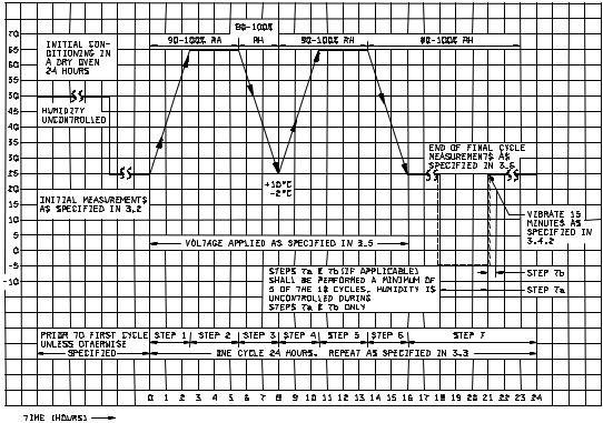
2.1 Chamber. A test chamber shall be used which can meet the temperature and humidity cycling specified on figure 106-1. The material used to fabricate the platforms and standoffs, which support the specimens, shall be nonreactive in high humidity. Wood or plywood shall not be used because they are resiniferous. Materials shall not be used if they contain formaldehyde or phenol in their composition. Provisions shall be made to prevent condensate from the chamber ceiling dripping onto the test specimens.
2.1.1Opening of the chamber door. During the periods when the humidity is ascending or descending, the chamber door should not be opened. If the chamber door must be opened, it should be opened during the 16th hour through the 24th hour of an individual cycle. While the chamber is at 25°C (77°F), and the relative humidity tolerance must be maintained, the chamber door should be opened only for a short period of time.
2.1.2Water. Steam, or distilled and demineralized, or deionized water, having a pH value between 6.0 and 7.2 at 23°C (73.4°F) shall be used to obtain the specified humidity. No rust or corrosive contaminants shall be imposed on the test specimens by the test facility.
3. PROCEDURE.
3.1Mounting. Specimens shall be mounted by their normal mounting means, in their normal mounting position, but shall be positioned so that they do not contact each other, and so that each specimen receives essentially the same degree of humidity.
3.2Initial measurements. Prior to step 1 of the first cycle, the specified initial measurements shall be made at room ambient conditions, or as specified.
METHOD 106G
8 February 2002
1 of 4
MIL-STD-202G
NOTES:
1.Allowance of 100 percent RH is intended to avoid problems in reading values close to 100 percent RH, but actual chamber operation shall be such so as to avoid condensation.
2.Unless otherwise specified, the steady state temperature tolerance is ±2°C at all points within the immediate vicinity of the specimens and the chamber surfaces.
3.Rate of change of temperature is unspecified; however, specimens shall not be subjected to radiant heat from chamber-conditioning processes.
4.Circulation of air in the chamber shall be at a minimum cubic rate per minute equivalent to 5 times the volume of the chamber.
FIGURE 106-1. Graphical representation of moisture-resistance test.
METHOD 106G
8 February 2002
2
MIL-STD-202G
3.3Number of cycles. Specimens shall be subjected to 10 continuous cycles, each as shown on figure 106-1. In the event of no more than one unintentional test interruption (power interruption or equipment failure) prior to the completion of the specified number of cycles (except for the last cycle), the cycle shall be repeated and the test may continue. Unintentional interruptions occurring during the last cycle require a repeat of the cycle plus an additional uninterrupted cycle. Any intentional interruption, or any unintentional interruption of greater than 24 hours requires a complete retest.
3.4Subcycle of step 7. During at least 5 of the 10 cycles, a low temperature subcycle and, if applicable, a vibration subcycle shall be performed.
3.4.1 Step 7a. At least 1 hour but not more than 4 hours after step 7 begins, the specimens shall be either removed from the humidity chamber, or the temperature of the chamber shall be reduced. Specimens shall then be conditioned at -10°C ±2°C (14°F ±3.6°F) with humidity not controlled, for 3 hours minimum as indicated on figure 106-1. When a separate cold chamber is not used, care should be taken to assure that the specimens are held at -10°C ±2°C (14°F ±3.6°F) for the full 3 hour period. (If step 7b is not applicable, the specimens shall be returned to 25°C (77°F) at 80 percent relative humidity minimum and kept there until the next cycle begins.)
3.4.2 Step 7b (when applicable). Within 15 minutes after completion of step 7a and with humidity not controlled and temperature at room ambient, specimens shall be vibrated for 15 minutes, using a simple harmonic motion having an amplitude of 0.03 inch (0.76 mm), (0.06 inch (1.52 mm) maximum total excursion), the frequency being varied uniformly between the approximate limits of 10 and 55 hertz (Hz). The entire frequency range, from 10 to 55 Hz and return to 10 Hz, shall be traversed in approximately 1 minute. After step 7b, the specimens shall be returned to 25°C (77°F) at 80 percent relative humidity minimum and kept there until the next cycle begins.
NOTE: Step 7b is not applicable to parts that include test schedules with vibration requirements (such as method 201 or method 204 of this standard). These parts must routinely be subjected to, and pass, these requirements.
NOTE: Allowance of 100 percent RH is intended to avoid problems in reading values close to 100 percent, but actual chamber operation shall be such so as to avoid condensation.
3.5Polarization and load. When applicable, polarization voltage shall be 100 volts dc, or as specified. The loading voltage shall be as specified.
3.6Final measurements.
3.6.1 At high humidity. Upon completion of step 6 of the final cycle (or step 7 if the subcycle of 3.4 is performed during the tenth cycle), when measurements at high humidity are specified, the specimens shall be maintained at a temperature of 25°C ±2°C (77°F ±3.6°F), and a RH of 80 percent minimum for a period of 1½ to 3½ hours, after which the specified measurements shall be made. Due to the difficulty in making measurements under high humidity conditions, the individual specification shall specify the particular precautions to be followed in making measurements under such conditions.
(NOTE: Allowance of 100 percent RH is intended to avoid problems in reading values close to 100 percent, but actual chamber operation shall be such so as to avoid condensation.)
3.6.2After high humidity. Upon removal from humidity chamber, final measurements shall be made within a period of 1 to 2 hours after the final cycle. During final measurements, specimens shall not be subjected to any means of artificial drying.
3.6.3After drying period. Following step 6 of the final cycle (or step 7 if the subcycle of 3.4 is performed during the tenth cycle), or following measurements at high humidity, if applicable, specimens shall be conditioned for 24 hours at the ambient conditions specified for the initial measurements (see 3.2) after which the specified measurements shall be made. Measurements may be made during the 24 hour conditioning period; however, any failures which occur shall be considered as failures and shall not be retested later for the purpose of obtaining an acceptable result.
METHOD 106G
8 February 2002
3
MIL-STD-202G
4.SUMMARY: The following details are to be specified in the individual specification:
a.Initial measurements and conditions, if other than room ambient (see 3.2).
b.When applicable, the polarization voltage if other than 100 volts (see 3.5).
c.Loading voltage (see 3.5).
d.Final measurements and measurement conditions (see 3.6).
METHOD 106G
8 February 2002
4