

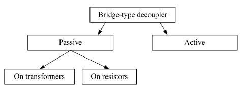
4. 2 Decoupling devices
The decoupling device is an eight-pole circuit with different attenuation between the poles. The transmission direction has small attenuation, and a direction of a decoupling (inhibition = protection) - high attenuation. The next conditions are required for the normal signal transmission and absence of generation (the Ideal TS):
1. Absence of attenuation in a transmission direction (А12=А41=0 dB).
2. Infinite attenuation in a decoupling direction (А42=А13 =∞ dB).
3. The input resistance balance with the load resistance.
The TS is called as a reversible if the next conditions are satisfied: А12=А21; А41=А14, in other way – they are irreversible.
Terminating set (Hybrid system) is used when parallel operating of filers, at the input and output circuits of amplifiers, VBC construction, pilot frequency inputting, using of duplex amplifier, for transition from 2w circuit to 4w and back when using the same frequency band for transmission and reception.
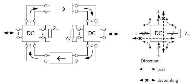
Figure 4.13
The transformer type of TS is widely used. Its circuit.

Figure 4.14
So the TS represents the differential transformer, to the 1-1 jacks of which the 2w line circuit is connected, to the 3-3 jacks – the circuit with the resistance Zbc that is balancing it. The 2-2 jacks are connected to the 4w transmission path of the channel, and the 4-4 jacks – to the receiving path. The input resistances should be chosen according to the next conditions in order to provide the decoupling:
Z3 = Zbc = m Z1
Z4 = m Z1/(m+1)
Z2 = (m+1) Z1/ n2
The transformation coefficient:
![]()
The equal-arm coefficient:
![]()
The TS is unequal-arm if m ≠ 1, and the TS is equal-arm if m=1.
I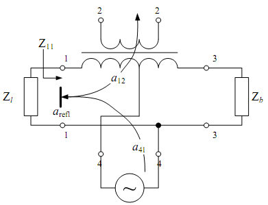 f
the half-windings have the same quantity of transformer coils (w1’’
= w1’) and the resistances (Z1=Zbc)
are equal a balanced bridge circuit is formed. When there is a
complete balance circuit i1
= ibc.
As the equal but oppositely directed currents flow through
half-windings, the equal but oppositely directed magnetic fluxes
appear. The total magnetic flux equals to zero, therefore
electromotive force and current i2
are absent at the output of the circuit. In this case the decoupling
device is balanced and the А42
=∞ and the feedback currents are absent.
f
the half-windings have the same quantity of transformer coils (w1’’
= w1’) and the resistances (Z1=Zbc)
are equal a balanced bridge circuit is formed. When there is a
complete balance circuit i1
= ibc.
As the equal but oppositely directed currents flow through
half-windings, the equal but oppositely directed magnetic fluxes
appear. The total magnetic flux equals to zero, therefore
electromotive force and current i2
are absent at the output of the circuit. In this case the decoupling
device is balanced and the А42
=∞ and the feedback currents are absent.
Figure 4.15
In
other case signals from the 4-4 pole will be reflected and sent to
the pole 2-2 (the input resistance
![]() ).
).
Attenuation in a 4-2 direction is equal to:
![]() .
.
The reflected attenuation is equal to:
![]() .
.
At
![]() TS is balanced and
TS is balanced and
![]() .
The balance attenuation is equal to
.
The balance attenuation is equal to
![]()
So
![]() .
TS is balanced if А42=А13
=∞ dB and TS is unbalanced if А42
≠ dB.
.
TS is balanced if А42=А13
=∞ dB and TS is unbalanced if А42
≠ dB.
The transmission direction attenuations:
T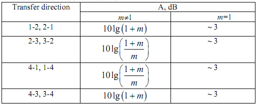 he
unbalance coefficient equals to:
he
unbalance coefficient equals to:

The circuit of the resistor type decoupling device.
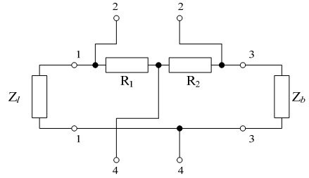
Figure 4.16
5 Transmission channels.
5.1 The main parameters of vbc
Channel – is the hookup of hardware, software and the propagation medium that provides the signals transmission from source to receiver.
Transmission channels in MTS SDC can be subdivided into:
VBCs (0.3-3.4 kHz)
broadband channels
SubG 12…24 kHz
PG 60…108 kHz
SG 312…552 kHz
MG 812…2044 kHz
Sound broadcasting channels
1st rank 0.05…6.5 kHz
2nd rank 0.05…10 kHz
VBC is widely used, so let’s observe it.
The simplified diagram of VBC is shown below.
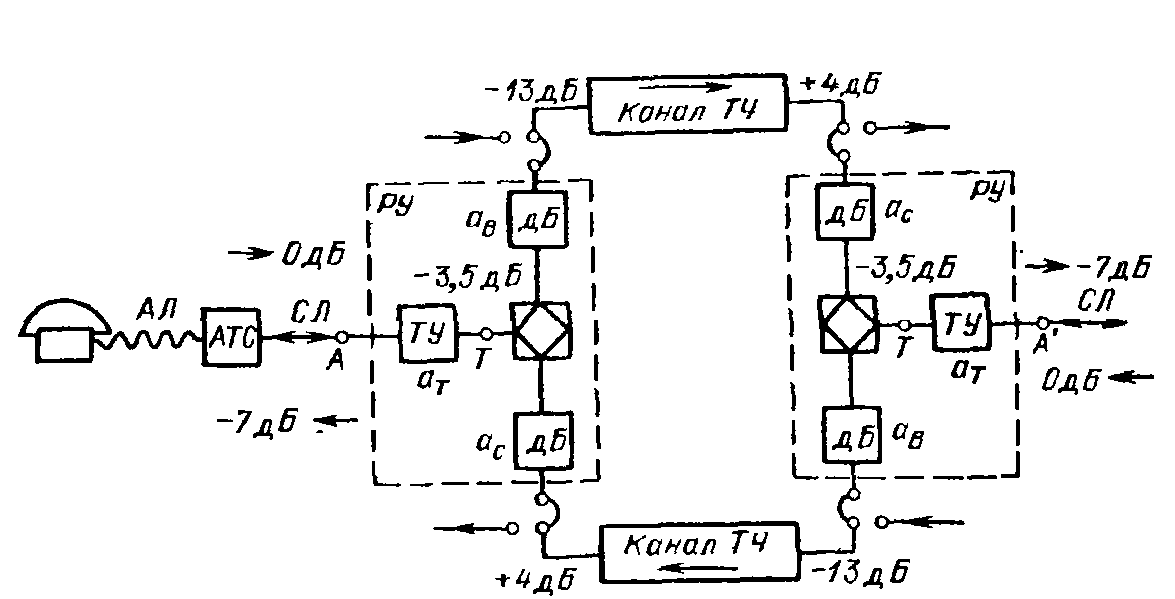

Figure 5.1
TY - TE – trough-line extender (adds 3.5 dB attenuation)
(СЛ) – trunk
(АЛ) – SL – subscriber line
(ATC) – AE – automatic exchange
DC - decoupler
The main parameters of VBC are:
The residual attenuation deviation from requirements (AFCh)
Group delay time characteristic (Phase-frequency characteristic)
Amplitude characteristic
We can determine that residual attenuation of VBC equals to (from the previous picture):
Ares = pin – pout = –13 – 4 = – 17 dB
In practice the frequency dependence is normalized by the residual attenuation deviation from the requirements but not by the residual attenuation.
ΔAres (f) = Ares (f) – Ares (800Hz)
Pout (f) = pin – Ares (f)
Pout (f) = pin – (Ares (800Hz) + ΔAres (f))
Norm: residual attenuation at 800 Hz frequency is – 17 dB.
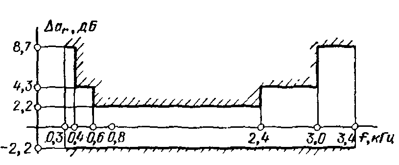
Residual attenuation at different frequencies is given by the following graph (template):
f, kHz |
0.3…0.4 |
0.4…0.6 |
0.6…2.4 |
2.4…3.0 |
3.0…3.4 |
ΔAres (f), dB |
1.4 |
0.72 |
0.6 |
0.72 |
1.4 |
f, kHz
dB
Figure 5.2
Speech intelligibility – upper limitation
Possibility of selfgeneration in the channel – lower limitation
Bandwidth of boundary frequencies of which (0.2 and 3.4 kHz) the residual attenuation is 8.7 dB higher than the residual attenuation at 800 Hz frequency is called efficiently transmitted frequency bandwidth. Phase frequency characteristic is taken as the group time delay for convenience:
τgr = – dφ(ω) / dω
There is a template for its normalization. Amplitude characteristic is normalized by the following way: when the measuring level is changed from -17.5 dB to +3.5 dB in the point of zero measuring level the residual attenuation deviation shouldn’t exceed 0.3 dB.
When measuring level is increased to 8.7 dB and 20 dB, ΔAres shouldn’t exceed 1.75 and 7.8 dB respectively.