

3 The multiplexing methods
There are batch (packet, Ethernet) and channel division of signals. The channel multiplexing varies in: linear, nonlinear (Quadrature Amplitude Modulation (QAM))), bridge.
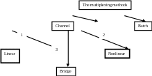
The examples of linear channeling methods are: FDC (1 L.w.), SDC (WDM), TDC (2 L.w.), bridge channeling (4 (Hybrid system = terminating set), 28 (about the VBC characteristics) L.w.). The linear multiplexing methods vary in: linearly independent signals division and orthogonal- channeling.
3.1 Frequency (spectral) division channeling fdc (sdc)
According to the definition MTS has to provide the simultaneous message transfer from N sources to N to addressees through the one physical circuit with a demanded quality.
The idea of frequency channeling (FDC) is used in ATS for simultaneous channel signals transfer through the physical circuit. FDC is one of the possible linear multiplexing methods (linear mathematical operators are used for the description of channeling). The transmitter has to generate the spectrum without channel overlapping for the channel division realization in receiver.
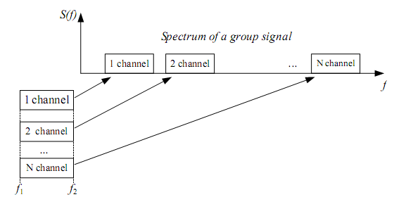
Figure 3.1
Such transformation is performed by the modulators.
It is known that with an analog method of signal’s transfer we use the following methods of modulation: AM, FM, PM, DSB-SC (double-sideband suppressed-carrier), SSB and others. Basically the single-sideband modulation (SSB) is used in MCS with FDC in order to reduce the width of a linear (group) signal spectrum. Let’s discuss the block diagram of MCS based on this principle (SSB).
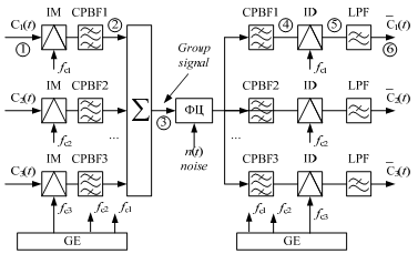
Figure 3.2
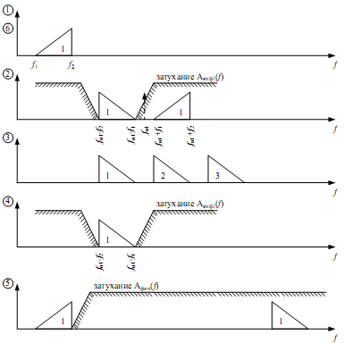
Figure 3.3
* The intended use of the units:
IM (individual modulator) – performs the initial signal transformation into the linear or intermediate spectrum, forming two sidebands.
BF (Band Filter) – extracts the useful sideband.
IDM (individual demodulators) - performs the inverse transformation of the linear or intermediate spectrum into intermediate or initial signal respectively, forming two sidebands.
CBF (Channel Band Filter) – extracts the channel signal from the group one.
LPF (Low-Pass Filter) – extracts the useful sideband that corresponds to the initial signal.
GE (Generating equipment) – forms the carrier frequencies and pilot-frequencies.
There are several methods of SSB modulator realization:
1. Filter method (in MTS of main and intraareal networks);
2. Phase difference method (in MTS of local networks);
3. Phase filter method (in the digital MTS).
Let's consider first two variants:
3.1.1 Filter method
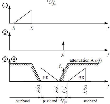
CBF
input
F igure
3.4
igure
3.4
F. method uses BM or DBM and filters (in a high amplitude mode).
There is useful signal (two sidebands) and side products of transformation (nonlinear distortions and harmonics), which level is high enough but they are out of useful spectrum bandwidth and can be easily filtered. But there are also nonlinear products that can appear in the useful bandwidth and can’t be filtered. Modulating signal’s value should be decreased enough comparing to the carrier frequency in order to decrease their influence.
1 2 3 1
1 - Stopband
2 - Bandwidth
3 - Transmission Range
The filter difficulty depends on relative band width of transmission range δ that equals to the ration of absolute transmission range (Δ) to carrier frequency. Filter can be built from the inductances and the capacitors if δ≥ 0.02 – 0.03. Otherway we have to use high performance filters or several steps of transformation. δ =Δ/fc.