

6.2 A Telephone Connection
The telephone network is probably the oldest connection-oriented network. A telephone switch, known as the central office, serves many thousands of subscribers. Each subscriber is directly connected to a central office via a dedicated twisted pair line, known as a local loop. Central offices are interconnected via time-division multiplexing (TDM) links, such as SONET/SDH links and PDH links (i.e., T1, E1, T3, and E3).
Figure 1.4 shows two telephones interconnected via two central offices. For presentation purposes, let us assume that the two central offices are connected via a T1 line. Transmission on a T1 line is organized into frames, with each frame containing 24 time slots. Each time slot is 8 bits long and carries a single voice call. The frame repeats every 128 µsec, meaning that a particular time slot occurs once every 128 µsec (i.e. 8000 times per second). Since it carries 8 bits at a time, the total bit rate of a time slot as it continuously repeats frame after frame is 64 Kbps.
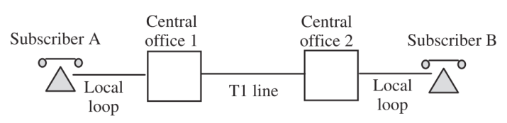
Figure 6.2 A simple telephone network.
Transmission on a T1 line is unidirectional; that is, data is routed from central office 1 to central office 2. For a bidirectional transmission between the two central offices, two separate T1 lines – each transmitting in the opposite direction – are needed.
In order for subscriber A to talk to subscriber B, a connection has to be first established. This connection is set up by the telephone network when A picks up the receiver and dials the number for the called party. A signaling protocol is used to set up a connection that runs through the central offices that are along the path from subscriber A to subscriber B. The connection involves:
(1) a dedicated line from subscriber A to central office 1;
(2) a time slot (e.g. time slot i) on the T1 line from central office 1 to central office
2; and
(3) a dedicated subscriber line from central office 2 to subscriber B.
In the opposite direction, it involves:
(1) a dedicated line from subscriber B to central office 2;
(2) time slot i on the T1 line from central office 2 to central office 1; and
(3) a dedicated subscriber line from central office 1 to subscriber A.
These resources are allocated to the phone call between subscriber A and subscriber B until one of them hangs up. A telephone connection is known as a circuit; thus, the telephone network is a circuit-switching network.
6.3 An atm Connection
Before we describe an ATM connection, we detour to examine briefly how packets are switched in a connectionless IP network. Let us assume that Computer A sends IP packets to Computer B, as shown in Figure 1.2. Each IP packet consists of a header and a payload, and the header contains the IP destination address of Computer B. When a packet arrives at IP router 1, the header is examined and the destination address is used in a forwarding routing table in order to find out the next IP router to which the IP packet has to be forwarded. In our example, the next hop router is IP router 2. IP packets arriving at IP router 2 are processed the same way. That is, the destination address is looked up in the router’s forwarding routing table in order to identify the next hop. IP router 2 will read that the destination address of the IP packets sent from Computer A is a local address, and it will simply send the IP packets to Computer B. The forwarding routing table in each IP router is constructed using a routing protocol, such as the open shortest path first (OSPF).
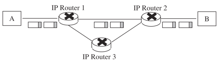
Figure 6.3 Routing IP packets
Let us now contrast the IP procedure for routing IP packets with the scheme used in ATM networks to switch ATM packets (commonly known as ATM cells). An ATM cell has a fixed size of 53 bytes. Of those, 5 bytes are used for the header and the remaining 48 for the payload. For a user to transmit traffic to a destination user over an ATM network, user A first has to request the establishment of a connection, as shown in the example in Figure 1.3. User A sends a SETUP message to ATM switch 1 (to which it is directly connected). The switch calculates a path to the destination ATM user, and then decides whether the path has enough free capacity to accept this new connection. If it does, then the switch forwards the SETUP message to the next switch on the path (switch 2), which in turn has to decide whether to accept the connection, based on how much free capacity it has. If it decides that it can accept the new connection, it forwards the SETUP message to the next switch on the path (switch 3), which forwards the SETUP request to user B. The connection is established when user B returns a CONNECT message, which is propagated all the way back to user A. The decision as to whether a switch can accept a new connection is crucial to the efficient operation of the network. Each ATM switch tracks all of the connections carried through its switch fabric, the amount of traffic transmitted over each connection, and the quality of service (QoS) requested by each connection. The decision to accept a new connection comes down to whether the prospective traffic can be switched according to the requested QoS, without affecting the QoS of other existing connections. When a connection is accepted, the switch allocates bandwidth on the outgoing link for the connection. It stops accepting new connections when it runs out of bandwidth, or when it reaches a certain percentage of utilization.
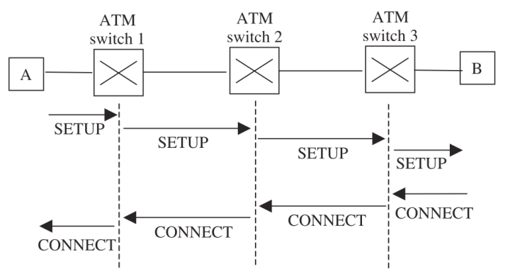
Figure 6.4 Successful establishment of an ATM connection.
The user starts transmitting ATM cells once it receives the CONNECT message. The ATM cells carry two fields in the header – the virtual path identifier (VPI) and the virtual connection identifier (VCI) – which are used to identify the connection. The ATM switch uses the combined VPI/VCI value to pass a cell through its switch fabric. Specifically, as in the case of an IP router, an ATM switch maintains a table that specifies the next hop for each VPI/VCI value. When a cell arrives at a switch, the virtual path and virtual connection identifiers check the table for the next ATM switch. The cell is then switched through the switch fabric to the output port that connects to the next ATM switch. The ATM table is considerably smaller than an IP forwarding routing table, since it only contains the existing ATM connections, rather than an entire set of IP addresses.
When user A completes its transmission to B, it tears down the connection by sending a RELEASE message to ATM switch 1. This message is propagated through the switches along the path, and each switch releases the bandwidth it had allocated to the connection. As we can see, transmitting packets through the IP network is a lot simpler than transmitting cells through an ATM network, since it is not necessary to establish a connection first. On the other hand, by establishing a connection in an ATM network, the network can provide QoS guarantees that are not possible in an IP network.