

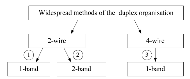
4 Duplex organization methods
Duplex
Picture 4.1
4.1.1 Two-wire one-band duplex
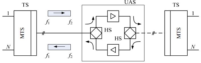
In this case signals in both directions are transferred through the one 2-wire line in the same frequency band. Compensation of the line attenuation is performed with the help of bidirectional amplifiers.
Picture 4.2
Separation of transfer and reception signals is performed with the help of hybrid system. Let’s observe the bidirectional amplifier in details.

Picture 4.3
In real systems attenuation in a decoupling direction is А 42< ∞ (in practice А 42 = 20 – 30 dB). Let’s designate HS1 attenuation in a decoupling direction as А1, and HS2 - А2.
Attenuation in a feedback loop is called as stability margin.
 .
.
The condition of selfgeneration in bidirectional amplifier is:
 The
amplitude condition and The phase condition
The
amplitude condition and The phase condition
where φfb – phase shift in a feedback loop.
Stable operating of such amplifier is possible when Аfb > 0.
The stability factor is:

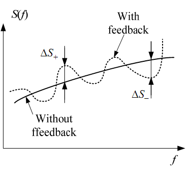
There are two types of feedback depending on the value of φfb:
Positive

Negative

Distortions in positive and negative FB are equal to Δ S+ and ΔS− where
 .
.
Where Sfb and ΔS – amplification of the amplifier without feedback and with feedback respectively.
35 Afb

Picture 4.4
4.1.2 Two-wire two-band duplex
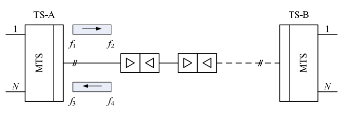
Two-wire line and different frequency bandwidths are used for simultaneous transmission and receiving in this mode.

Picture 4.5
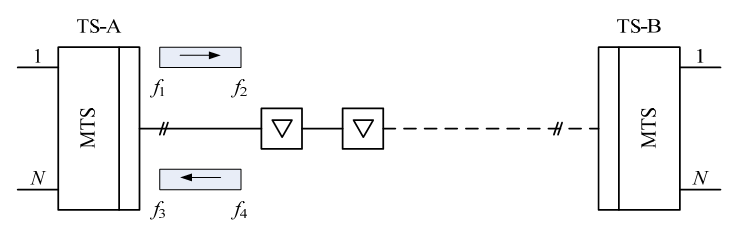
Communication organization circuit with using of two amplifiers.
Picture 4.6
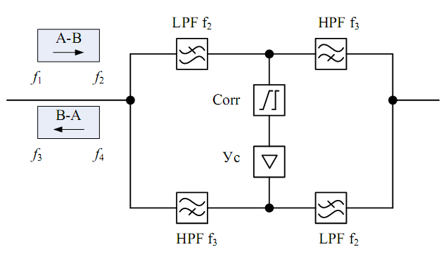
Simplified block diagram of intermediate station.

Picture 4.7
Guiding filters are used for separation of transmission and reception paths. They also suppress nonlinear products that appear at the amplifier`s output. It eliminates the possibility of self-generation of the amplifier in the UAS and TS.
The linear signal spectrum:
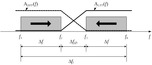
Δfpr
Picture 4.8
 ;
;
 .
.
Bandwidth
of a linear signal is Δfl
>2Δf because of the protective transmission range Δfpr.
it is necessary to the ratio in order to simplify the guiding filter
circuits
 i.e.
i.e.
 .
.
The amplification frequency bandwidth of amplifier shouldn’t exceed 5 octaves:

 ;
;
 ;
;
 ;
;
 .
.
Communication organization circuit with using of one amplifier.
Picture 4.9
The simplified block diagram of intermediate station.
Amp
Picture 4.10
The spectrum is analogous to a duplex with two amplifiers variant. In this circuit the amplifier should provide the amplification in a range f1 … f4. There are following conditions of a f1 frequency choice:
 .
.
So
 .
.
4.1.3 A four-wire one-band duplex
The block diagram of the communication organization.
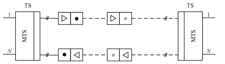
Picture 4.11
The simplified block diagram of intermediate station.
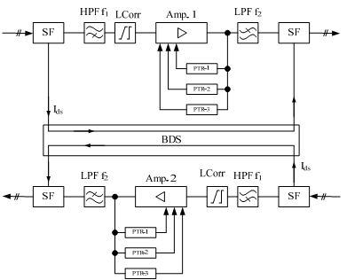
Picture 4.12
PTR – is the Pilot Tone Receiver.
LPF and HPF serve for linear noises and harmonious distortions deletion at the output of amplifier. The board of the distance supply (BDS) contains a voltage regulator for all blocks of station supply.