

1.2 The basic elements of the pn (the network elements)
The basic elements of the PN are: the telecommunications (telecommunication links), the transmission systems, the station equipment of the transmission systems, and the cable-line work of the transmission link.
The different mediums are used for the organization of the PN telecommunications. Public broadcast (radio communication) or the wire communication facilities (aerial telecommunication link (ATL), cable telecommunication link (CTL)) can be used. There are symmetrical, coaxial and fiber-optic CTLs.
Radio communications are the radio-relay types of telecommunication (RRTL), in which the USW (ultra-short waves= VHF very high-frequency waves) wave band is used. That is the communication in the line of sight 30-50 km. The intermediate RR stations are used in order to organize the longer communications.

It’s generally used for the TV programs transmission.
The satellite communication systems are also used.

It takes a lot of time.
Transmission system (TrS) – is the hookup of the technical facilities and the propagation medium that allows the independent transmission of the given channels number at a required distance with the required quality, so it provides the channels and the group highway to the user. (N>1 Multichannel TrS, MTS)
The channel – is the hookup of the technical facilities and the propagation medium that allows the signal transmission at a required distance with the required quality.
Cable-line work of the transmission link – telecommunication works and other civil engineering infrastructure objects that are developed or adapted to communication cables placement.
Telecommunication link (transmission link) TL – is the hookup of the transmission systems that are using the same cable-link works and connecting the corresponding network nodes.
2 Section Transmission systems
2.1 Functions and the basic elements of the transmission systems
TrS consists of the station equipment and the cable-line work.

Symmetrical cable
TrS (MTS)
nonserviced
serviced
Use the next notation conventions in the structure charts:
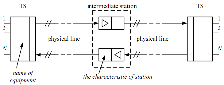
Figure 2.1
Functions of the terminal station
TS at the transmitting site forms the convenient for the transmission over the physical line group signal from the initial one.
TS at the receiving site performs the inverse transformation (extracts and recovers the initial signal from the group one). The group signal is attenuated and distorted while transmission. So in order to recover it the amplifiers and correctors are used in the analog TrS (ATS) and regenerators – in the digital TrS (DTs).
By analogy the amplifiers and correctors (regenerators) are also used in the intermediate stations (IS).
Functions of the intermediate station
The intermediate station provides the required transmission quality. The signals quality depends on the value of distortions and noises that can be added to this signal. The basic quality test in ATS is the signal/noise ratio in the channel, and for DTS – is the bit error probability in the information.
The Line Path
The line path consists of the station equipment and propagation medium. The station equipment includes the TS, the IS and all maintenance services (remote supply, service traffic, telemechanics and remote supervision). TS are situated at the terminal communication point TCP, IT – at the intermediate communication point ICP (serviced and nonserviced).

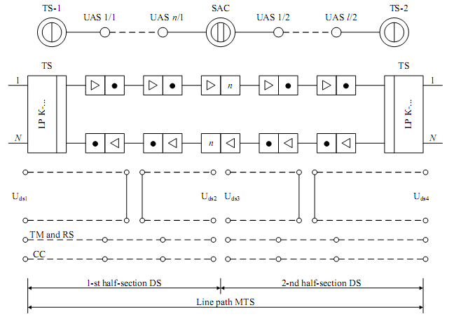
NRS 1/1
NRS 1/n
SRS
NRS 2/1
NRS 2/n
U rs 1
U rs 2
U rs 3
U rs 4
ST
Figure 2.2
NRS – nonserviced repeater station
SRS – serviced repeater station
TS – terminal communication station
Automatic gain control by the ground temperature
n - Automatic gain control by the pilot frequency
A mplifier
The remote supply of the NRS is performed from the TS and from the SRS. The supply is performed from two sides by half sections.
The type of ST is the service section communication that provides the intercommunication between each amplifying section.
There are 4 types of ST:
Service section communication (between the NRS and the nearest SRS) – is used during the main installation, the alarm status, in case of the repairing need.
Service station-by-station communication (between the nearest SRSs that are used for the maintenance of the given LP section).
Service main communication (between the network nodes).
Service network communication (the whole network management).

3,4
Artificial circuit is used for ST organization in case with MTS on a symmetrical cable, and low frequency bandwidth (0.3 – 3.4 kHz) - in case with a coaxial cable. TM and RS transmission is carried out in the upper part of the line spectrum. RS is organized similarly to ST (lower than 4 kHz – coax. cable at 50 Hz or 0 Hz).
The LP characteristics provide the organization of the long distance communication with the required quality. The signal’s quality is determined by the distortions and real noises that have to meet the requirements.
The basic method to obtain the good quality signal is the correct determination of the nominal repeater section length. It’s necessary to situate the ISs at this distance between each other in order to obtain the signal’s level at the input of the IS higher than the acceptable level and the difference from the noises more than acceptable immunity.
Immunity – is the logarithmic value of the signal-noise ratio expressed in dB.

This equation is comfortable to represent in next view:

If the Po – is the etalon power = 1 mW, the 1st summand – is the absolute power level of the signal ps, and the 2nd summand – is the absolute power level of the noise pn.
The usage of the ISs provides the required signal’s immunity from the noises and the noise stability. The higher immunity the higher noise stability will be.
Let’ explain this by using the level diagram (LD).