

3.1.2 Phase difference method
T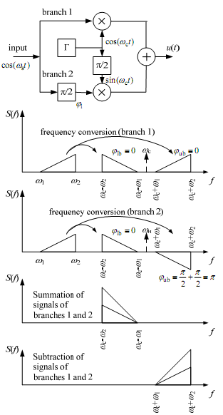 here
are phase inverters and DBM modulators in circuit and it allows
reducing the costs of the MTS equipment.
here
are phase inverters and DBM modulators in circuit and it allows
reducing the costs of the MTS equipment.
Let’s φs=0.
φlsb = π/2- π/2
φusb = π/2+ π/2 = π
Disadvantage is the complexity of realization of the phase shifter on 90° in the 2 branch.
If the φl ≠ π/2 the second sideband isn’t compensated completely and can cause the influence on the next channel of MTS. Therefore the given method has found application in the local and radio networks, where the usage of inexpensive equipment without filters is required. 8 kHz per channel is used to avoid the influence between the channels. Advantages:
1. The group signal power economy (One sideband is transmitted);
2. The noise stability is higher comparing with АМ (carrier frequency is absent).
Figure 3.5
3.2 Time division channeling

Figure 3.6
The idea of time channeling (TDC) is used in DTS for simultaneous channel signals transfer through the physical circuit. The transmitter has to generate the frame without channel time overlapping for the channel division realization in receiver. In signal processing, Discretization (sampling) is the reduction of a continuous signal to a discrete signal. A common example is the conversion of a sound wave (a continuous-time signal) to a sequence of samples (a discrete-time signal). The Sampling theorem shows that a bandlimited analog signal that has been sampled can be perfectly reconstructed from an infinite sequence of samples if the sampling rate exceeds 2Fmax samples per second, where Fmax is the highest frequency in the original signal. If a signal contains a component at exactly Fmax hertz, then samples spaced at exactly 1/(2Fmax) seconds do not completely determine the signal.


Figure 3.7
Sampling of a continuous signal can be performed by using the PAM (Pulse-Amplitude Modulation) method. The pulses of different channels are sent to the line between the pulses of one channel – formation of the group PAM-signal.
The frequency limited (by using of the LPFtr) information signal is sent to the input of electronic switches (ES) that perform channel modulator functions. Carriers control the ES operation, they are sent from generating equipment (GE) and represent periodical sequence of pulses with repetition frequency equal to the Fsamp = 1/Tsamp. GE consists of periodical pulses sequence reference generator (RG) and pulse channel distributor (PCD). PCD represents the multisection delay line, each section’s delay is Δt and is determined by the channels number. The synchronizing signal is sent at the end of each sampling period in order to open the ESs of the recipient path at a corresponding time. Synchronizing signal is the synchronizing pulse (SP) that has to be different from the channel pulses, so it has the maximal amplitude and occupies 2 times wider time period. SP is sent from the GE through the clock driver (CD) and multiplexed with the channel signals in the pulse bitstream collector (C). SP in the recipient path is sent to the GErec through the sync selector (SS). ESrec extracts the channel signal from the group one and is operated by the GErec (PCDrec). LPFrec transforms the pulse PAM-signal into the continuous one (the output voltage is proportional to the PAM-signal’s envelope).