

3.1.3 Read, translate and retell. Optical Instruments
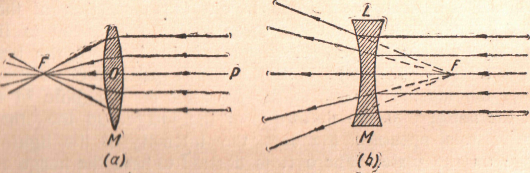
Lenses. - Lenses are bodies made of transparent material and bounded by faces having a cylindrical or spherical form. Although lenses differ much in form they may be divided into two classes according to the way in which they act on a parallel beam of light. Consider the lens in Figure 39a on which parallel rays are incident. Each ray is bent toward the normal to the surface on entering the lens and away from the normal on emerging from the lens. In this way, the rays above the axis PO are bent downward and those below it are bent upward. After leaving the lens, the rays converge to a point F, called the principal focus. Such a lens is a converging lens. If the incident rays are parallel to each other, the incident wave front is a plane perpendicular to the incident rays. When this wave front emerges from the lens, it has been changed to a concave wave front that converges to the focus. When the bounding surfaces of the lens are very convex, the lens converges the rays rapidly. This gives the lens a short focal length.
a b
Fig. 39 a - Principal focus of a converging lens. The incident rays are
parallel to the principal axis POF; b - Principal focus of a diverging lens
When the bounding surfaces are only convex, the lens has a long focal length. In order that all the rays may come to a point after leaving the lens, the beam of light must be restricted to a narrow bundle near the principal aixis of the lens. For an extended beam the outer rays will not pass through the same point as the rays near the axis.
When the surfaces of the lens are concave instead of convex, the lens makes the rays that pass through it more divergent, and for this reason it is known as a diverging lens. In Figure 39b parallel rays are incident on a concave lens. On entering the lens, the rays are bent toward the normal as before, and on leaving they are bent away from the normal. In this case, however, the emerging rays are bent away from the principal axis. They appear on leaving the lens to come from a point F behind the lens. When the incident rays are parallel to each other and to the principal axis, this point from which the rays appear to come on leaving the lens is the principal focus. This is only an apparent focus because the light does not really come from it, but the effect on the left-hand side of the lens is the same as if the light actually came from this point behind the lens. This kind of focus from which the light appears to come is a virtual focus. It is to be carefully distinguished from a real focus through which the light actually goes.
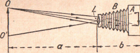
Figure 40 - Photographic camera
If the lens is convex, and the incident rays come from a point source, the incident wave front is spherical, and the emerging wave front is the surface of a sphere with its center at the image. If the lens is concave, the curvature of the wave front is increased in passing through the lens, and the image is behind the lens.
The Photographic Camera. - The simplest application of lenses for optical purposes is in an ordinary photographic camera (Figure 40). A lens or combination of lenses in one end of the camera produces a real image of an external object on the photographic plate or film at the other end of the camera. The distance between the lens and the photographic plate or film can be altered so as to focus the image on the plate. Sometimes the photographic plate is replaced by a ground-glass screen on which the image is cast, and then the lens is moved into such a position that the image is sharply focused on the ground glass. The plate or film is then substituted for the ground glass. The bellows В serves to exclude all the light except that which comes from the object. It also makes possible the to-and-fro motion of the lens necessary in the focusing.
To avoid spherical aberration, i.e., the distortion of the image because all the rays do not come to the same focus, and to limit the quantity of light, a diaphragm is placed in front of the lens. This diaphragm restricts the rays to those which pass through the central portion of the lens. The smaller the diameter of the hole in the diaphragm, the better is the definition of the image. On the other hand, the smaller this opening, the less the intensity of the light forming the image on the plate. Where it is desired to have the image as bright as possible, the choice of the size of the opening in the diaphragm becomes a compromise between diminished brightness on the one hand and definition on the other hand.
Condenser
 Y
Y
X
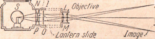
Figure 41 - Projection lantern. It produces real, inverted,
and magnified images
Projection Lantern. - The projection lantern, which is used to throw an image of a brilliantly illuminated object on a screen consists of a powerful source of light S (Figure 41), a large condensing lens NP, and a front or objective, lens LM. The condensing lens NP collects the light from the source S and sends it through the slide OI, so that this slide is brilliantly illuminated. The objective LM then produces a real image of the slide OI on the screen XY. Since the slide OI is just outside the principal focus of the lens LM, the image on the screen is enlarged. This image is also real and inverted. The magnification produced by the lantern is obtained from an application of the law for the magnification of a lens.
Simple Microscope. - When an object is placed slightly nearer to a converging lens than its focus, an eye brought up to the lens sees a virtual, erect, and magnified image A'B' (Figure 42). A lens used in this way constitutes a simple microscope. In order to obtain the greatest advantage, the eye should be as near as possible to the lens. In this way, the field of view is made as large as possible, and the distance of the virtual image A'B' from the eye for distinct vision is made as large as possible.
In order to find the magnification of a lens used in this way, it is necessary to consider that the apparent size of an object is determined by the angle it subtends at the eye. Now for most distinct vision, an object must be about 10 in. from a normal eye. If an object is placed at a greater distance than this, the image on the retina is smaller and its details are not seen so distinctly. When the object is placed nearer than 10 in., the image on the retina is blurred. When an object is examined with the aid of the magnifying glass, the object is brought nearer to the eye than would be possible for distinct vision without the magnifying glass. In Fig. 42 the angles subtended at the center of the lens by the object AB and the image A'B' are the same. But OD is the distance of distinct vision, and, if the lens were absent, the eye could not see AB distinctly until it was removed to ab.
A'
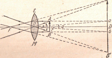
Figure 42 A simple microscope. It produces