


VHF Propagation 7
VHF Frequency Spread
The frequencies in the part of the VHF band that may be of concern to the pilot are as follows:
88 to 107.95 MHz |
Broadcasting (FM) |
108 to 117.95 MHz |
Radio Navigation (AM and FM) |
118 to 136.975 MHz Radio Communication (AM)
This is the band that used for Aeronautical
Mobile Service voice communications
(AM stands for amplitude modulation and FM for frequency modulation)
VHF Frequency Separation
Sidebands and Bandwidth
The spread of side frequencies above and below the carrier frequency are known respectively as the upper and lower sidebands. The total spread of frequencies in the modulated emission is known as the bandwidth of the signal. A voice (or music) transmission consists of many different audio frequencies, up to at least 5 kHz, impressed on the carrier wave. Consequently, many side frequencies exist in the modulated signal, which may have a bandwidth of at least 10 kHz. Such a signal is classified as an A3E emission; an example is VHF R/T.
VHF Bandwidth
The bandwidth allocated to VHF frequencies is at present, for the most part, 25 kHz or 0.025 MHz, i.e. the spacing between one channel and another. Wherever channels are separated by 25 kHz, only the first five digits should be used, not more than 2 significant digits after the decimal point; however, when “reading back” a frequency, all six digits should be repeated. In the case of these being 2 zeros, a single zero is considered significant.
118.0 transmitted as ONE ONE EIGHT DECIMAL ZERO
118.025 transmitted as ONE ONE EIGHT DECIMAL ZERO TWO FIVE
However, this is being reduced to 8.33 kHz (one third of 25 kHz) and is already mandatory for aircraft using the upper airspace over Europe under Eurocontrol. Wherever VHF channels are separated by 8.33 kHz, all 6 digits of the numerical designator should be used to identify the transmitting channel. Three digits after the decimal are used for all channels.
118.005 transmitted as ONE ONE EIGHT DECIMAL ZERO ZERO FIVE
VHF Propagation 7
137
7 VHF Propagation
Propagation VHF 7
VHF Propagation Characteristics
Propagation Paths
The path of a radio wave from a transmitter to a receiver many miles away is not necessarily direct. The following paragraphs describe the various paths a radio signal can follow. In many cases, the signal may be reaching the receiver by more than one path at the same time, and because of the different path lengths, there will be phase differences between the signals. Such phase differences affect the resultant signal strength. For instance, if two waves from the same transmitter travel by different paths and arrive 180° out of phase, they will cancel each other if their amplitudes are the same. The resultant signal strength will be zero, so no signal will be received. Changes in phase difference will cause changes in signal strength, so producing the effect known as ‘fading’.
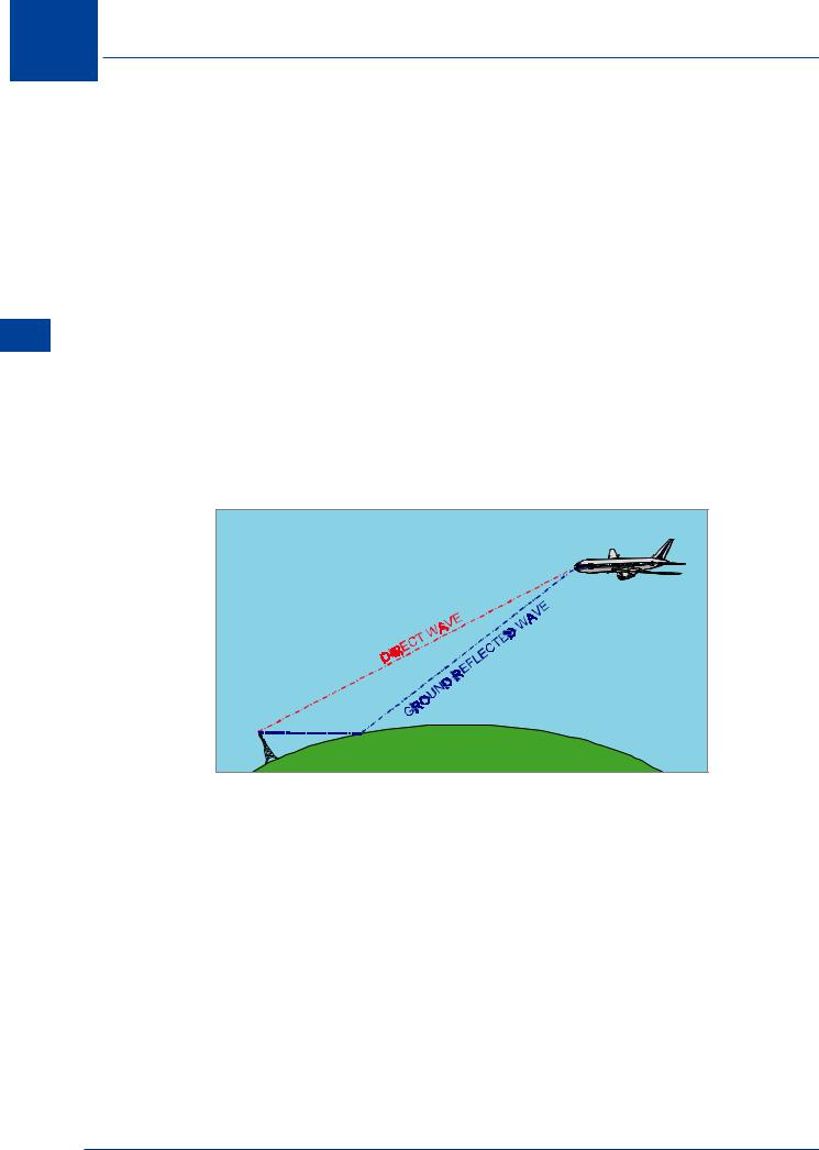
Direct and Ground-reflectedWaves
A signal which travels in a straight line between transmitter and receiver is called the direct wave. In addition to this, there is normally a signal arriving at the receiver after reflection at the earth’s surface. This is the ground-reflected wave. These two waves are jointly known as the Space Wave. (In this and other diagrams, the abbreviation Tx is used for transmitter and Rx for Receiver.)
Rx |
Tx |
EARTH |
Figure 7.2 Space wave
Since the direct and reflected waves follow different paths, they may arrive at the receiver with large phase differences. The situation is further complicated by a change in phase, which occurs at the point of reflection of the ground-reflected wave. The net result is that, for instance, an aircraft flying towards a ground station may suffer fading or temporary loss of VHF communications with that station. The range at which this occurs depends on ground aerial height above the surface, aircraft altitude, and frequency. For instance, with VHF R/T, except in freak conditions, the curvature of the earth gives protection from mutual interference between stations using a common frequency, provided they are well-separated geographically.
138
VHF Propagation 7
Factors Affecting VHF Propagation
Attenuation
The term attenuation means the loss in strength of a radio signal as range from the transmitter increases. The signal strength received is inversely proportional to the distance from the transmitter. A wave becomes attenuated as range increases because:-
•The radio energy available is spread over a greater area.
•Radio energy is lost to the earth, the atmosphere, and sometimes to the ionized layers
above the earth.
One factor on which the operational range of a radio emission depends, is the transmitter power. The range obtainable is proportional to the square root of the power; in other words, if the range is to be doubled, the transmitter power must be quadrupled.
Refraction
As a general rule, radio signals travel in straight lines, that is, they follow great circle paths over the surface of the earth. Under certain circumstances, however, the path of a signal may change direction. This change of direction is known as refraction. The amount of refraction varies considerably, depending on conditions and on frequency. In the VHF range of frequencies there is negligible refraction.
Effective Range of VHF
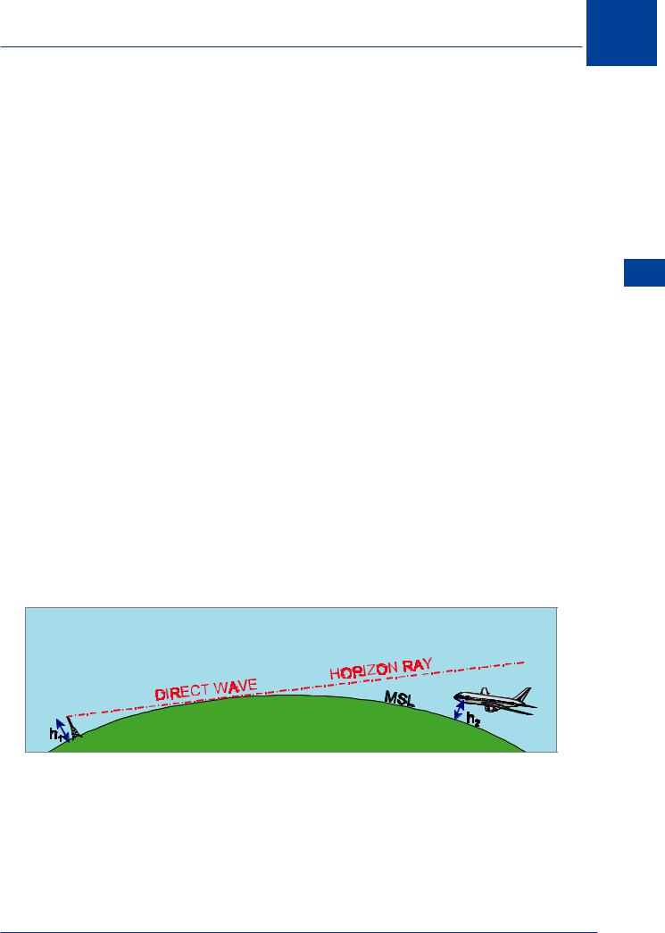
Line of Sight Range
The curvature of the earth limits the use of the direct wave. It can be seen that the aircraft ‘below the horizon’ cannot use the direct wave for communications.
The lowest direct wave is just tangential to the surface and is known as the ‘horizon ray’. It will be appreciated that direct wave communications for the aircraft could be restored by either raising the height of the ground aerial or increasing the aircraft’s altitude.
|
Rx |
Tx |
EARTH |
|
Figure 7.3 Line of sight
A formula used for calculating the maximum range of direct wave reception is:
Range (NM) |
= |
1.23 (√h1 + √h2) |
Where h1 |
= |
height of ground aerial (feet AMSL) |
h2 |
= |
aircraft altitude (feet AMSL) |
VHF Propagation 7
139
7 VHF Propagation
Propagation VHF 7
This formula allows for a small amount of refraction in the lower layers of the atmosphere, which gives a slightly better range than would be obtained if the direct wave followed a perfectly straight path without any downward refraction. Under normal conditions, the space wave provides the only propagation path for frequencies above about 30 MHz.
Therefore, except on fairly rare occasions, communications in the VHF and higher bands suffer from line of sight transmission, with range limited by the curvature of the earth and any high ground which interrupts the line of sight. Note that the range limitation imposed by line of sight transmission is useful when there is a shortage of available frequencies.
Freak Propagation
It has been stated that for frequencies above about 30 MHz, transmission is normally ‘line of sight’ so that propagation is by means of the space wave. Under certain conditions of freak or ‘anomalous’ propagation, however, ranges much greater than line of sight ranges can be achieved by means of duct propagation and scatter propagation.
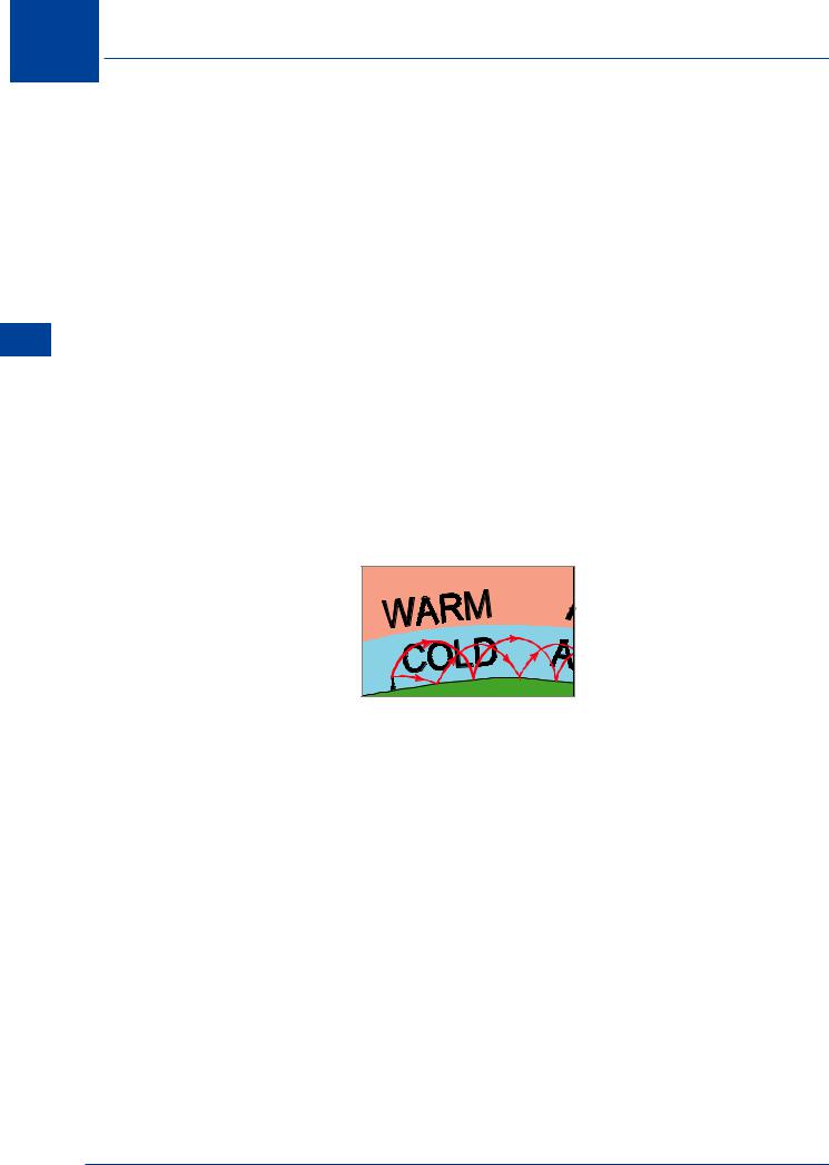
Duct Propagation
This effect, also called ‘super-refraction’, is associated with a temperature inversion and a rapid decrease in humidity with height. Such meteorological conditions are most often found at the surface over land, in high pressure conditions at night and in the early morning. A warm air mass over a cold sea can also produce the effect. It can also occur at higher levels.
Figure 7.4 Duct propagation
The way in which radio signals can be ‘trapped’ in a duct of cold air is shown above. This process sometimes permits reception of signals at the surface hundreds of miles beyond the horizon. The effect is most common in the SHF and UHF bands, but is also encountered in the VHF band if the duct is sufficiently deep (say, 500 ft). Duct propagation can cause annoying interference between control towers using the same R/T frequency, and false range indications on ground radar screens.
Scatter Propagation
The E-layer sometimes contains areas of very high ionization density which can produce weak sky waves (known as ‘Sporadic-E’ reflections) in the VHF band. The effect is unpredictable and the sky waves are scattered at random in the forward direction from the transmitter. With specially designed aerials, scatter propagation can sometimes be used to provide intermittent extended range VHF R/T, but it is not a reliable means of communication. Scatter propagation can cause mutual interference between VHF radio aids sharing a frequency and normally protected from interference by line of sight transmission. Television programmes also suffer from interference due to this effect.
140