
- •Textbook Series
- •Contents
- •1 Properties of Radio Waves
- •Introduction
- •The Radio Navigation Syllabus
- •Electromagnetic (EM) Radiation
- •Polarization
- •Radio Waves
- •Wavelength
- •Frequency Bands
- •Phase Comparison
- •Practice Frequency (
- •Answers to Practice Frequency (
- •Questions
- •Answers
- •2 Radio Propagation Theory
- •Introduction
- •Factors Affecting Propagation
- •Propagation Paths
- •Non-ionospheric Propagation
- •Ionospheric Propagation
- •Sky Wave
- •HF Communications
- •Propagation Summary
- •Super-refraction
- •Sub-refraction
- •Questions
- •Answers
- •3 Modulation
- •Introduction
- •Keyed Modulation
- •Amplitude Modulation (AM)
- •Single Sideband (SSB)
- •Frequency Modulation (FM)
- •Phase Modulation
- •Pulse Modulation
- •Emission Designators
- •Questions
- •Answers
- •4 Antennae
- •Introduction
- •Basic Principles
- •Aerial Feeders
- •Polar Diagrams
- •Directivity
- •Radar Aerials
- •Modern Radar Antennae
- •Questions
- •Answers
- •5 Doppler Radar Systems
- •Introduction
- •The Doppler Principle
- •Airborne Doppler
- •Janus Array System
- •Doppler Operation
- •Doppler Navigation Systems
- •Questions
- •Answers
- •6 VHF Direction Finder (VDF)
- •Introduction
- •Procedures
- •Principle of Operation
- •Range of VDF
- •Factors Affecting Accuracy
- •Determination of Position
- •VDF Summary
- •Questions
- •Answers
- •7 Automatic Direction Finder (ADF)
- •Introduction
- •Non-directional Beacon (NDB)
- •Principle of Operation
- •Frequencies and Types of NDB
- •Aircraft Equipment
- •Emission Characteristics and Beat Frequency Oscillator (BFO)
- •Presentation of Information
- •Uses of the Non-directional Beacon
- •Plotting ADF Bearings
- •Track Maintenance Using the RBI
- •Homing
- •Tracking Inbound
- •Tracking Outbound
- •Drift Assessment and Regaining Inbound Track
- •Drift Assessment and Outbound Track Maintenance
- •Holding
- •Runway Instrument Approach Procedures
- •Factors Affecting ADF Accuracy
- •Factors Affecting ADF Range
- •Accuracy
- •ADF Summary
- •Questions
- •Answers
- •8 VHF Omni-directional Range (VOR)
- •Introduction
- •The Principle of Operation
- •Terminology
- •Transmission Details
- •Identification
- •Monitoring
- •Types of VOR
- •The Factors Affecting Operational Range of VOR
- •Factors Affecting VOR Beacon Accuracy
- •The Cone of Ambiguity
- •Doppler VOR (DVOR)
- •VOR Airborne Equipment
- •VOR Deviation Indicator
- •Radio Magnetic Indicator (RMI)
- •Questions
- •In-flight Procedures
- •VOR Summary
- •Questions
- •Annex A
- •Annex B
- •Annex C
- •Answers
- •Answers to Page 128
- •9 Instrument Landing System (ILS)
- •Introduction
- •ILS Components
- •ILS Frequencies
- •DME Paired with ILS Channels
- •ILS Identification
- •Marker Beacons
- •Ground Monitoring of ILS Transmissions
- •ILS Coverage
- •ILS Principle of Operation
- •ILS Presentation and Interpretation
- •ILS Categories (ICAO)
- •Errors and Accuracy
- •Factors Affecting Range and Accuracy
- •ILS Approach Chart
- •ILS Calculations
- •ILS Summary
- •Questions
- •Answers
- •10 Microwave Landing System (MLS)
- •Introduction
- •ILS Disadvantages
- •The MLS System
- •Principle of Operation
- •Airborne Equipment
- •Question
- •Answer
- •11 Radar Principles
- •Introduction
- •Types of Pulsed Radars
- •Radar Applications
- •Radar Frequencies
- •Pulse Technique
- •Theoretical Maximum Range
- •Primary Radars
- •The Range of Primary Radar
- •Radar Measurements
- •Radar Resolution
- •Moving Target Indication (MTI)
- •Radar Antennae
- •Questions
- •Answers
- •12 Ground Radar
- •Introduction
- •Area Surveillance Radars (ASR)
- •Terminal Surveillance Area Radars
- •Aerodrome Surveillance Approach Radars
- •Airport Surface Movement Radar (ASMR)
- •Questions
- •Answers
- •13 Airborne Weather Radar
- •Introduction
- •Component Parts
- •AWR Functions
- •Principle of Operation
- •Weather Depiction
- •Control Unit
- •Function Switch
- •Mapping Operation
- •Pre-flight Checks
- •Weather Operation
- •Colour AWR Controls
- •AWR Summary
- •Questions
- •Answers
- •14 Secondary Surveillance Radar (SSR)
- •Introduction
- •Advantages of SSR
- •SSR Display
- •SSR Frequencies and Transmissions
- •Modes
- •Mode C
- •SSR Operating Procedure
- •Special Codes
- •Disadvantages of SSR
- •Mode S
- •Pulses
- •Benefits of Mode S
- •Communication Protocols
- •Levels of Mode S Transponders
- •Downlink Aircraft Parameters (DAPS)
- •Future Expansion of Mode S Surveillance Services
- •SSR Summary
- •Questions
- •Answers
- •15 Distance Measuring Equipment (DME)
- •Introduction
- •Frequencies
- •Uses of DME
- •Principle of Operation
- •Twin Pulses
- •Range Search
- •Beacon Saturation
- •Station Identification
- •VOR/DME Frequency Pairing
- •DME Range Measurement for ILS
- •Range and Coverage
- •Accuracy
- •DME Summary
- •Questions
- •Answers
- •16 Area Navigation Systems (RNAV)
- •Introduction
- •Benefits of RNAV
- •Types and Levels of RNAV
- •A Simple 2D RNAV System
- •Operation of a Simple 2D RNAV System
- •Principle of Operation of a Simple 2D RNAV System
- •Limitations and Accuracy of Simple RNAV Systems
- •Level 4 RNAV Systems
- •Requirements for a 4D RNAV System
- •Control and Display Unit (CDU)
- •Climb
- •Cruise
- •Descent
- •Kalman Filtering
- •Questions
- •Appendix A
- •Answers
- •17 Electronic Flight Information System (EFIS)
- •Introduction
- •EHSI Controller
- •Full Rose VOR Mode
- •Expanded ILS Mode
- •Full Rose ILS Mode
- •Map Mode
- •Plan Mode
- •EHSI Colour Coding
- •EHSI Symbology
- •Questions
- •Appendix A
- •Answers
- •18 Global Navigation Satellite System (GNSS)
- •Introduction
- •Satellite Orbits
- •Position Reference System
- •The GPS Segments
- •The Space Segment
- •The Control Segment
- •The User Segment
- •Principle Of Operation
- •GPS Errors
- •System Accuracy
- •Integrity Monitoring
- •Differential GPS (DGPS)
- •Combined GPS and GLONASS Systems
- •Questions
- •Answers
- •19 Revision Questions
- •Questions
- •Answers
- •Specimen Examination Paper
- •Appendix A
- •Answers to Specimen Examination Paper
- •Explanation of Selected Questions
- •20 Index

Radio PropagationTheory |
|
2 |
|
||
|
|
|
Sky Wave
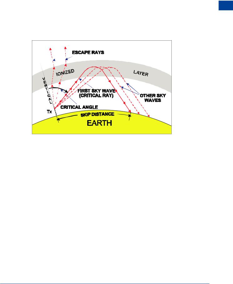
The ionization levels in the layers increase towards the centre of the layer. This means that as a radio wave transits a layer it encounters an increasing density of ions as it moves to the centre of the layer and decreasing density as it moves out of the layer. If the radio waves travel across the layer at right angles they will be retarded, but will maintain a straight path. However, if the waves penetrate the layer at an angle they will be refracted away from the normal as they enter, then back towards the normal as they exit the layer.
Radio Propagation Theory 2
Figure 2.9 Sky wave propagation - critical angle
The amount of refraction experienced by the radio waves is dependent on both the frequency and the levels of ionization. If the radio wave refracts to the (earth) horizontal before it reaches the centre of the layer then it will continue to refract and will return to the surface of the earth as sky wave; this is total internal refraction at the layer.
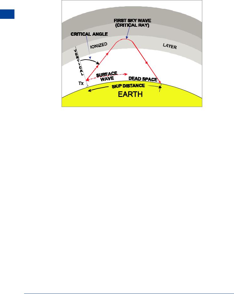
Starting from the vertical at the transmitter, with a frequency which penetrates the ionosphere, as the angle between the vertical and the radio wave increases, an angle will be reached where total internal refraction occurs and the wave returns to the surface. This is known as the first returning sky wave and the angle (measured from the vertical) at which this occurs is known as the critical angle. The distance from the transmitter to the point where the first returning sky wave appears at the surface is known as the skip distance. As sky waves occur in the LF, MF and HF frequency bands there will also be some surface wave present. From the point where the surface wave is totally attenuated to the point where the first returning sky wave appears there will be no detectable signal, this area is known as dead space.
27

2 |
|
Radio PropagationTheory |
|
||
|
|
|
Theory Propagation Radio 2
Figure 2.10 Sky wave propagation - dead space
The height at which full internal refraction occurs is dependent on frequency, but, as a generalization frequencies up to 2 MHz will be refracted at the E-layer and from 2 – 50 MHz at the F-layers. Sky wave is only likely to occur above 50 MHz when there are abnormal ionospheric conditions associated with intense sunspot or solar flare activity, therefore, VHF frequencies used for navigation systems do not produce sky waves.
Effect of Change in Ionization Intensity
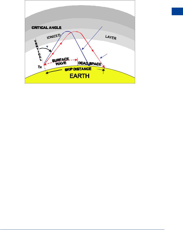
Since the reason for the refraction is the ionization of the upper atmosphere it follows that if ionization intensity changes, then the amount of refraction of radio waves will also change. At a given frequency, as ionization increases the refractive index and hence the amount of refraction affecting the radio waves will also increase. This means that refraction will take place at a smaller critical angle and the skip distance and dead space will decrease. Conversely, a decrease in ionization will result in an increase in critical angle, skip distance and dead space.
28

Radio PropagationTheory |
|
2 |
|
||
|
|
|
|
2 |
|
HIGH |
Theory |
|
|
||
IONIZATION |
Radio Propagation |
|
LOW |
||
|
||
IONIZATION |
|
|
Figure 2.11 Sky wave propagation - effect of increased ionization |
|
Effect of Change of Frequency
For a given ionization intensity, the amount of refraction of radio waves decreases as frequency increases, because as frequency increases the energy contained in the radio wave increases and therefore refraction decreases. So, as frequency increases, the critical angle will increase and the skip distance and dead space will also increase. As frequency increases, the surface wave range will decrease, so there is an increase in dead space caused by both the increase in skip distance and decrease in surface wave range. Conversely, a decrease in frequency will give a decrease in critical angle, skip distance and dead space.
Height of the Layers
The skip distance will also be affected by the altitude of the refracting layers. As the altitude of the layer increases then the skip distance will also increase and greater ranges will be experienced by refraction at the F-layer than the E-layer.
29

2 |
|
Radio PropagationTheory |
|
||
|
|
|
Theory Propagation Radio 2
LF and MF SkyWave Propagation
During the day the D-layer absorbs radio energy at frequencies below about 2 MHz (LF and MF bands). At night the D-layer is effectively non-existent so, at these frequencies, sky waves, refracted at the E-layer are present. This means the sky waves at LF and MF are not reliable for continuous long range use and the presence of sky waves at night at the relatively short ranges associated with these lower frequencies will cause interference with short range navigation (and broadcasting) systems relying on surface wave reception. This affects ADF and will be discussed in more detail in Chapter 7.
E LAYER
D LAYER
Sky Wave
EARTH |
Surface Wave |
|
DAY
E LAYER
EARTH
NIGHT
Figure 2.12 LF/MF Sky wave propagation
30

Radio PropagationTheory |
|
2 |
|
||
|
|
|
Achievable Ranges
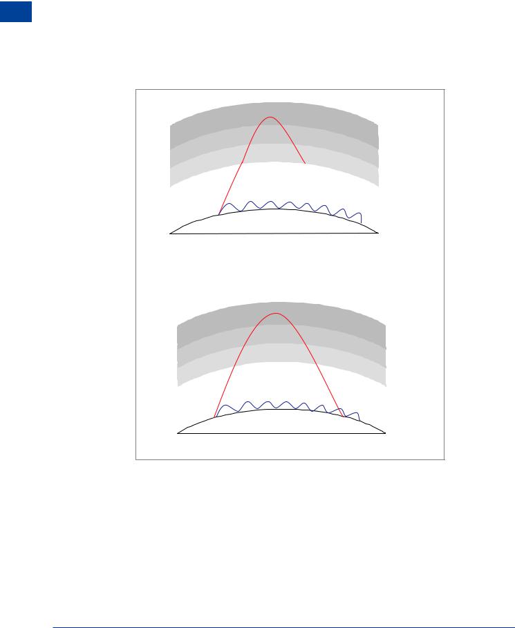
The maximum range for sky wave will be achieved when the path of the radio wave is tangential at the surface of the earth at both the transmitter and receiver.
A simple calculation shows that the average maximum range for refraction from the E-layer at 125 km is 1350 NM, and the average maximum range from the F-layer at 225 km is 2200 NM. These ranges will obviously change as the height of the ionized layers changes.
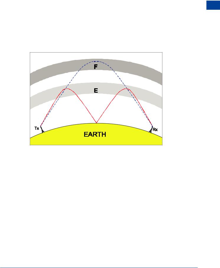
Multi-hop sky wave occurs when the wave is refracted at the ionosphere then the sky wave is reflected back from the surface of the earth to the ionosphere etc. Multi-hop sky wave can achieve ranges of half the diameter of the earth.
Figure 2.13 Multi-hop Sky wave propagation
Radio Propagation Theory 2
31