

Instrument Landing System (ILS) |
|
9 |
|
||
|
|
|
DME Paired with ILS Channels
A DME that is frequency paired with an ILS supplements or replaces the range information from markers/locators.
The DME ranges are zero referenced to the ILS runway threshold.
The DME is protected only within the ILS localizer service area up to 25 000 ft. When necessary and notified, the DME is also used for published ‘SIDs’ and ‘STARs’. In such cases the DME coverage is increased. The use of a DME outside the stated limits may give rise to errors.
ILS Identification
Separate identification is unnecessary for ILS localizer and glide path transmissions as the localizer and glide path frequencies are paired. The selection of the localizer VHF frequency automatically energizes the glide path receiver circuits.
The Ident on the localizer transmission is a 2 or 3 letter Morse signal at 7 groups/min. The first letter is usually “I”.
The identification is automatically suppressed if the ILS becomes unserviceable or is withdrawn. When an ILS is undergoing maintenance, or is radiating for test purposes only, the identification coding will either be removed completely or replaced by a continuous tone. Under these conditions no attempt should be made to use the ILS as completely erroneous indications may be received.
Additionally, in some instances, because of an unserviceable glide path, the ILS may be radiating for localizer approaches only, in which case the identification coding will be radiating. In this case ATC will warn all users of this fact and no attempt should be made to use the glide path.
Marker Beacons
Two markers are required for each installation and a third may be added if considered necessary at a particular site.
When a marker is used in conjunction with the back course of a localizer, it should have an identification signal that is clearly distinguishable from the front course markers.
Instrument Landing System (ILS) 9
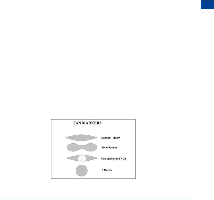
Figure 9.2 Marker beacon radiation patterns
149

9 |
|
Instrument Landing System (ILS) |
|
||
|
|
|
(ILS) System Landing Instrument 9
The radiation patterns for ILS marker beacons is vertical and appears lens shaped or bone shaped in plan view. Figures 9.2 and 9.3 show the horizontal and vertical profiles of ILS marker beacons. The signal is only received if the aircraft is flying within the fan; it is not a directional aid. Reception is indicated by synchronous aural identifiers and lights as shown in the following table.
Figure 9.3 The outer marker and the middle marker
|
Cockpit Light |
Ident |
Modulating |
Pitch |
Touchdown |
|
|
|
Frequency |
|
Range |
|
|
|
|
|
|
OM |
BLUE |
2 dashes/sec |
400 Hz |
Low |
6.5 – 11.1 km |
|
|
|
|
|
(3.5 – 6 NM) |
|
|
|
|
|
|
MM |
AMBER |
Alternate dots |
1300 Hz |
|
1050 m ± 150 m |
|
|
and dashes |
|
Medium |
(3500’ ± 500’) |
|
|
3/sec |
|
|
|
|
|
|
|
|
|
IM |
WHITE |
6 dots/sec |
3000 Hz |
High |
75 - 450 m |
|
|
|
|
|
(250’ – 1500’) |
|
|
|
|
|
|
Figure 9.4
Z markers have cylindrical vertical radiation patterns. They are used to mark airway reporting points or co-located with an NDB. Due to the cone of silence directly above an NDB, either Z markers or fan-shaped markers provide an indication when the aircraft is overhead.
150

Instrument Landing System (ILS) |
|
9 |
|
||
|
|
|
Ground Monitoring of ILS Transmissions
Both the localizer and the glide path are automatically monitored by equipment located in an area of guaranteed reception. This equipment will act when:
•the localizer at the reference datum shifts from the runway centre line by more than 35 ft for Cat I, 25 ft for Cat II or 20 ft for Cat III.
•the glide path angle changes more than 0.075 × basic glide path angle.
•there is a power reduction in output of more than 50% from any transmitter.
The monitoring unit will provide warning to a control point and cause any of the following to occur before a standby transmitter is activated:
•Cessation of all radiation.
•Removal of identification and navigational components of the carrier.
•Cat II or III ILS may permit operation to the lower categories I or II.
ILS Coverage
Localizer
The localizer coverage sector extends from the transmitter to distances of:
•25 NM (46.3 km) within plus or minus 10° from the centre line.
•17 NM (31.5 km) between 10° and 35° from the centre line.
•10 NM (18.5 km) outside ± 35° if coverage is provided.
These limits may be reduced to 18 NM within 10° sector and 10 NM within the remainder of the coverage when alternative navigational facilities provide satisfactory coverage within the intermediate approach area.
Glide Path
The glide path coverage extends from the transmitter to a distance of at least:
10 NM (18.5 km) in sectors of 8° in azimuth on each side of the centre line.
The vertical coverage is provided from 0.45θ up to 1.75θ above the horizontal where θ is the promulgated glide path angle. The lower limit may be reduced to 0.3θ if required to safeguard the promulgated glide path intercept procedure.
ILS coverage is illustrated in Figures 9.5, 9.6 and 9.7.
Note: These are the sectors within which the ILS localizer and glide path emissions must provide correct indications. Radiated energy exists outside these vertical and horizontal sectors.
Instrument Landing System (ILS) 9
151

9 |
|
Instrument Landing System (ILS) |
|
||
|
|
|
(ILS) System Landing Instrument 9
|
17 NM |
25° |
|
|
|
|
|
Centre of |
|
25 NM 10° |
|
Localizer |
|
Course |
|
Antenna |
|
|
|
|
|
Line |
System |
10° |
|
|
|
25° |
|
|
|
Figure 9.5 Localizer coverage |
|
|
|
Runway Touchdown Point |
8°
Centre Line
8°
10 NM
Azimuth Angle
Figure 9.6 Glide path horizontal coverage
Runway Touchdown Point
 1.75 × θ
θ
0.45 × θ
(Or to such lower angle, down to 0.3 × θ, as required to safeguard the promulgated glide path procedure)
Figure 9.7 Glide path vertical coverage
152