- •Textbook Series
- •Contents
- •1 Properties of Radio Waves
- •Introduction
- •The Radio Navigation Syllabus
- •Electromagnetic (EM) Radiation
- •Polarization
- •Radio Waves
- •Wavelength
- •Frequency Bands
- •Phase Comparison
- •Practice Frequency (
- •Answers to Practice Frequency (
- •Questions
- •Answers
- •2 Radio Propagation Theory
- •Introduction
- •Factors Affecting Propagation
- •Propagation Paths
- •Non-ionospheric Propagation
- •Ionospheric Propagation
- •Sky Wave
- •HF Communications
- •Propagation Summary
- •Super-refraction
- •Sub-refraction
- •Questions
- •Answers
- •3 Modulation
- •Introduction
- •Keyed Modulation
- •Amplitude Modulation (AM)
- •Single Sideband (SSB)
- •Frequency Modulation (FM)
- •Phase Modulation
- •Pulse Modulation
- •Emission Designators
- •Questions
- •Answers
- •4 Antennae
- •Introduction
- •Basic Principles
- •Aerial Feeders
- •Polar Diagrams
- •Directivity
- •Radar Aerials
- •Modern Radar Antennae
- •Questions
- •Answers
- •5 Doppler Radar Systems
- •Introduction
- •The Doppler Principle
- •Airborne Doppler
- •Janus Array System
- •Doppler Operation
- •Doppler Navigation Systems
- •Questions
- •Answers
- •6 VHF Direction Finder (VDF)
- •Introduction
- •Procedures
- •Principle of Operation
- •Range of VDF
- •Factors Affecting Accuracy
- •Determination of Position
- •VDF Summary
- •Questions
- •Answers
- •7 Automatic Direction Finder (ADF)
- •Introduction
- •Non-directional Beacon (NDB)
- •Principle of Operation
- •Frequencies and Types of NDB
- •Aircraft Equipment
- •Emission Characteristics and Beat Frequency Oscillator (BFO)
- •Presentation of Information
- •Uses of the Non-directional Beacon
- •Plotting ADF Bearings
- •Track Maintenance Using the RBI
- •Homing
- •Tracking Inbound
- •Tracking Outbound
- •Drift Assessment and Regaining Inbound Track
- •Drift Assessment and Outbound Track Maintenance
- •Holding
- •Runway Instrument Approach Procedures
- •Factors Affecting ADF Accuracy
- •Factors Affecting ADF Range
- •Accuracy
- •ADF Summary
- •Questions
- •Answers
- •8 VHF Omni-directional Range (VOR)
- •Introduction
- •The Principle of Operation
- •Terminology
- •Transmission Details
- •Identification
- •Monitoring
- •Types of VOR
- •The Factors Affecting Operational Range of VOR
- •Factors Affecting VOR Beacon Accuracy
- •The Cone of Ambiguity
- •Doppler VOR (DVOR)
- •VOR Airborne Equipment
- •VOR Deviation Indicator
- •Radio Magnetic Indicator (RMI)
- •Questions
- •In-flight Procedures
- •VOR Summary
- •Questions
- •Annex A
- •Annex B
- •Annex C
- •Answers
- •Answers to Page 128
- •9 Instrument Landing System (ILS)
- •Introduction
- •ILS Components
- •ILS Frequencies
- •DME Paired with ILS Channels
- •ILS Identification
- •Marker Beacons
- •Ground Monitoring of ILS Transmissions
- •ILS Coverage
- •ILS Principle of Operation
- •ILS Presentation and Interpretation
- •ILS Categories (ICAO)
- •Errors and Accuracy
- •Factors Affecting Range and Accuracy
- •ILS Approach Chart
- •ILS Calculations
- •ILS Summary
- •Questions
- •Answers
- •10 Microwave Landing System (MLS)
- •Introduction
- •ILS Disadvantages
- •The MLS System
- •Principle of Operation
- •Airborne Equipment
- •Question
- •Answer
- •11 Radar Principles
- •Introduction
- •Types of Pulsed Radars
- •Radar Applications
- •Radar Frequencies
- •Pulse Technique
- •Theoretical Maximum Range
- •Primary Radars
- •The Range of Primary Radar
- •Radar Measurements
- •Radar Resolution
- •Moving Target Indication (MTI)
- •Radar Antennae
- •Questions
- •Answers
- •12 Ground Radar
- •Introduction
- •Area Surveillance Radars (ASR)
- •Terminal Surveillance Area Radars
- •Aerodrome Surveillance Approach Radars
- •Airport Surface Movement Radar (ASMR)
- •Questions
- •Answers
- •13 Airborne Weather Radar
- •Introduction
- •Component Parts
- •AWR Functions
- •Principle of Operation
- •Weather Depiction
- •Control Unit
- •Function Switch
- •Mapping Operation
- •Pre-flight Checks
- •Weather Operation
- •Colour AWR Controls
- •AWR Summary
- •Questions
- •Answers
- •14 Secondary Surveillance Radar (SSR)
- •Introduction
- •Advantages of SSR
- •SSR Display
- •SSR Frequencies and Transmissions
- •Modes
- •Mode C
- •SSR Operating Procedure
- •Special Codes
- •Disadvantages of SSR
- •Mode S
- •Pulses
- •Benefits of Mode S
- •Communication Protocols
- •Levels of Mode S Transponders
- •Downlink Aircraft Parameters (DAPS)
- •Future Expansion of Mode S Surveillance Services
- •SSR Summary
- •Questions
- •Answers
- •15 Distance Measuring Equipment (DME)
- •Introduction
- •Frequencies
- •Uses of DME
- •Principle of Operation
- •Twin Pulses
- •Range Search
- •Beacon Saturation
- •Station Identification
- •VOR/DME Frequency Pairing
- •DME Range Measurement for ILS
- •Range and Coverage
- •Accuracy
- •DME Summary
- •Questions
- •Answers
- •16 Area Navigation Systems (RNAV)
- •Introduction
- •Benefits of RNAV
- •Types and Levels of RNAV
- •A Simple 2D RNAV System
- •Operation of a Simple 2D RNAV System
- •Principle of Operation of a Simple 2D RNAV System
- •Limitations and Accuracy of Simple RNAV Systems
- •Level 4 RNAV Systems
- •Requirements for a 4D RNAV System
- •Control and Display Unit (CDU)
- •Climb
- •Cruise
- •Descent
- •Kalman Filtering
- •Questions
- •Appendix A
- •Answers
- •17 Electronic Flight Information System (EFIS)
- •Introduction
- •EHSI Controller
- •Full Rose VOR Mode
- •Expanded ILS Mode
- •Full Rose ILS Mode
- •Map Mode
- •Plan Mode
- •EHSI Colour Coding
- •EHSI Symbology
- •Questions
- •Appendix A
- •Answers
- •18 Global Navigation Satellite System (GNSS)
- •Introduction
- •Satellite Orbits
- •Position Reference System
- •The GPS Segments
- •The Space Segment
- •The Control Segment
- •The User Segment
- •Principle Of Operation
- •GPS Errors
- •System Accuracy
- •Integrity Monitoring
- •Differential GPS (DGPS)
- •Combined GPS and GLONASS Systems
- •Questions
- •Answers
- •19 Revision Questions
- •Questions
- •Answers
- •Specimen Examination Paper
- •Appendix A
- •Answers to Specimen Examination Paper
- •Explanation of Selected Questions
- •20 Index
7 Automatic Direction Finder (ADF)
Holding
When density of traffic or bad weather delay an aircraft’s landing at an airport, the air traffic controller directs it to a Holding Area. The area, also known as a ‘stack’, is organized over a ‘radio’ beacon where each waiting aircraft flies a special circuit separated vertically from other aircraft by a minimum of 1000 ft. An aircraft drops to the next level as soon as it is free of other traffic, until it finally flies from the stack and comes in to land.
(ADF) Finder Direction Automatic 7
Figure 7.20 The holding system
96
Automatic Direction Finder (ADF) |
|
7 |
|
||
|
|
|
Runway Instrument Approach Procedures
Most aerodromes have NDB runway instrument approach procedures. The pilot flies the published procedure in order to position the aircraft in poor weather conditions for a visual landing. The NDB may also be used in conjunction with other runway approach aids for the same purpose.
Automatic Direction Finder (ADF) 7
Figure 7.21 Example of an NDB instrument approach
97
7 |
|
Automatic Direction Finder (ADF) |
|
||
|
|
|
(ADF) Finder Direction Automatic 7
Factors Affecting ADF Accuracy
Designated Operational Coverage (DOC)
The DOC of NDBs is based upon a daytime protection ratio (signal/noise ratio of 3:1) between wanted and unwanted signals that permits the required level of bearing accuracy. At ranges greater than those promulgated, bearing errors will increase. Adverse propagation conditions particularly at night will also increase bearing errors.
Static Interference
There are two types of static interference that can affect the performance of ADF:
Precipitation static is generated by the collision of water droplets and ice crystals with the aircraft. It causes a reduction in the signal/noise ratio which affects the accuracy of the bearings and can, in extreme circumstances completely mask the incoming signal. The indications on the RMI/RBI will be a wandering needle and the audio will have a background hiss, which is also likely to be present on VHF frequencies.
Thunderstorms have very powerful discharges of static electricity across the electromagnetic spectrum including LF and MF. These discharges cause bearing errors in the ADF. A static discharge in a cumulonimbus cloud (Cb) will be heard as a loud crackle on the audio and the needle will move rapidly to point to the Cb. When there are several active cells close together, it is possible for the needle to point to them for prolonged periods. Care must be taken in the use of ADF when Cb activity is forecast. It has been said that during Cb activity the only sensible use of the ADF is to indicate where the active cells are.
Night Effect
By day the D-region absorbs signals in the LF and MF bands. At night the D-region disappears allowing sky wave contamination of the surface wave being used. This arises for two reasons: phase interference of the sky wave with the surface wave because of the different paths and the induction of currents in the horizontal elements of the loop aerial. The effect is reduced by the aerial design having very short vertical elements and by screening the aerial above and below, but the contamination is not eliminated. The effect first becomes significant at 70 - 100 NM from the NDB. The effect is manifest by fading of the audio signal and the needle ‘hunting’ and is worst around dawn and dusk, when the ionosphere is in transition.
If ADF is to be used at night:
•Positively identify the NDB call sign.
•Continue to check the tuning and the identification.
•Avoid use of the equipment within 1 hour of sunrise or sunset.
•Use NDBs within their promulgated range which is valid during daytime only.
•Treat bearings with caution if the needle wanders and the signal fades.
•Cross-check NDB bearing information against other navigation aids.
98
Automatic Direction Finder (ADF) |
|
7 |
|
||
|
|
|
Station Interference
Due to congestion of stations in the LF and MF bands, the possibility of interference from stations on or near the same frequency exists. This will cause bearing errors. By day, the use of an NDB within the DOC will normally afford protection from interference. However, at night, one can expect interference even within the DOC because of sky wave contamination from stations out of range by day. Therefore positive identification of the NDB at night should always be carried out.
Mountain Effect
Mountainous areas can cause reflections and diffraction of the transmitted radio waves to produce errors in ADF systems. These errors will increase at low altitude and can be minimized by flying higher.
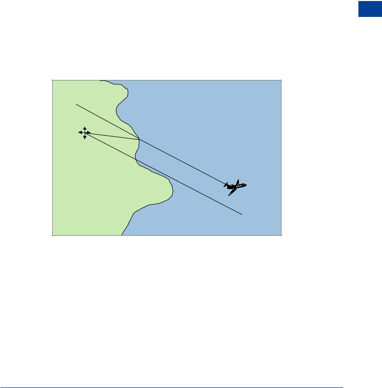
Coastal Refraction
Radio waves speed up over water due to the reduced absorption of energy (attenuation) compared to that which occurs over land. This speeding up causes the wave front to bend (refract) away from its normal path and pull it towards the coast. Refraction is negligible at 90° to the coast but increases as the angle of incidence increases.
Figure 7.22 Coastal refraction
For an aircraft flying over the sea the error puts the aircraft position closer to the coast than its actual position.
The effect can be minimised by:
•Using NDBs on or near to the coast.
•Flying higher.
•Using signals that cross the coast at or near to 90°
Automatic Direction Finder (ADF) 7
99