

- •Textbook Series
- •Contents
- •1 Properties of Radio Waves
- •Introduction
- •The Radio Navigation Syllabus
- •Electromagnetic (EM) Radiation
- •Polarization
- •Radio Waves
- •Wavelength
- •Frequency Bands
- •Phase Comparison
- •Practice Frequency (
- •Answers to Practice Frequency (
- •Questions
- •Answers
- •2 Radio Propagation Theory
- •Introduction
- •Factors Affecting Propagation
- •Propagation Paths
- •Non-ionospheric Propagation
- •Ionospheric Propagation
- •Sky Wave
- •HF Communications
- •Propagation Summary
- •Super-refraction
- •Sub-refraction
- •Questions
- •Answers
- •3 Modulation
- •Introduction
- •Keyed Modulation
- •Amplitude Modulation (AM)
- •Single Sideband (SSB)
- •Frequency Modulation (FM)
- •Phase Modulation
- •Pulse Modulation
- •Emission Designators
- •Questions
- •Answers
- •4 Antennae
- •Introduction
- •Basic Principles
- •Aerial Feeders
- •Polar Diagrams
- •Directivity
- •Radar Aerials
- •Modern Radar Antennae
- •Questions
- •Answers
- •5 Doppler Radar Systems
- •Introduction
- •The Doppler Principle
- •Airborne Doppler
- •Janus Array System
- •Doppler Operation
- •Doppler Navigation Systems
- •Questions
- •Answers
- •6 VHF Direction Finder (VDF)
- •Introduction
- •Procedures
- •Principle of Operation
- •Range of VDF
- •Factors Affecting Accuracy
- •Determination of Position
- •VDF Summary
- •Questions
- •Answers
- •7 Automatic Direction Finder (ADF)
- •Introduction
- •Non-directional Beacon (NDB)
- •Principle of Operation
- •Frequencies and Types of NDB
- •Aircraft Equipment
- •Emission Characteristics and Beat Frequency Oscillator (BFO)
- •Presentation of Information
- •Uses of the Non-directional Beacon
- •Plotting ADF Bearings
- •Track Maintenance Using the RBI
- •Homing
- •Tracking Inbound
- •Tracking Outbound
- •Drift Assessment and Regaining Inbound Track
- •Drift Assessment and Outbound Track Maintenance
- •Holding
- •Runway Instrument Approach Procedures
- •Factors Affecting ADF Accuracy
- •Factors Affecting ADF Range
- •Accuracy
- •ADF Summary
- •Questions
- •Answers
- •8 VHF Omni-directional Range (VOR)
- •Introduction
- •The Principle of Operation
- •Terminology
- •Transmission Details
- •Identification
- •Monitoring
- •Types of VOR
- •The Factors Affecting Operational Range of VOR
- •Factors Affecting VOR Beacon Accuracy
- •The Cone of Ambiguity
- •Doppler VOR (DVOR)
- •VOR Airborne Equipment
- •VOR Deviation Indicator
- •Radio Magnetic Indicator (RMI)
- •Questions
- •In-flight Procedures
- •VOR Summary
- •Questions
- •Annex A
- •Annex B
- •Annex C
- •Answers
- •Answers to Page 128
- •9 Instrument Landing System (ILS)
- •Introduction
- •ILS Components
- •ILS Frequencies
- •DME Paired with ILS Channels
- •ILS Identification
- •Marker Beacons
- •Ground Monitoring of ILS Transmissions
- •ILS Coverage
- •ILS Principle of Operation
- •ILS Presentation and Interpretation
- •ILS Categories (ICAO)
- •Errors and Accuracy
- •Factors Affecting Range and Accuracy
- •ILS Approach Chart
- •ILS Calculations
- •ILS Summary
- •Questions
- •Answers
- •10 Microwave Landing System (MLS)
- •Introduction
- •ILS Disadvantages
- •The MLS System
- •Principle of Operation
- •Airborne Equipment
- •Question
- •Answer
- •11 Radar Principles
- •Introduction
- •Types of Pulsed Radars
- •Radar Applications
- •Radar Frequencies
- •Pulse Technique
- •Theoretical Maximum Range
- •Primary Radars
- •The Range of Primary Radar
- •Radar Measurements
- •Radar Resolution
- •Moving Target Indication (MTI)
- •Radar Antennae
- •Questions
- •Answers
- •12 Ground Radar
- •Introduction
- •Area Surveillance Radars (ASR)
- •Terminal Surveillance Area Radars
- •Aerodrome Surveillance Approach Radars
- •Airport Surface Movement Radar (ASMR)
- •Questions
- •Answers
- •13 Airborne Weather Radar
- •Introduction
- •Component Parts
- •AWR Functions
- •Principle of Operation
- •Weather Depiction
- •Control Unit
- •Function Switch
- •Mapping Operation
- •Pre-flight Checks
- •Weather Operation
- •Colour AWR Controls
- •AWR Summary
- •Questions
- •Answers
- •14 Secondary Surveillance Radar (SSR)
- •Introduction
- •Advantages of SSR
- •SSR Display
- •SSR Frequencies and Transmissions
- •Modes
- •Mode C
- •SSR Operating Procedure
- •Special Codes
- •Disadvantages of SSR
- •Mode S
- •Pulses
- •Benefits of Mode S
- •Communication Protocols
- •Levels of Mode S Transponders
- •Downlink Aircraft Parameters (DAPS)
- •Future Expansion of Mode S Surveillance Services
- •SSR Summary
- •Questions
- •Answers
- •15 Distance Measuring Equipment (DME)
- •Introduction
- •Frequencies
- •Uses of DME
- •Principle of Operation
- •Twin Pulses
- •Range Search
- •Beacon Saturation
- •Station Identification
- •VOR/DME Frequency Pairing
- •DME Range Measurement for ILS
- •Range and Coverage
- •Accuracy
- •DME Summary
- •Questions
- •Answers
- •16 Area Navigation Systems (RNAV)
- •Introduction
- •Benefits of RNAV
- •Types and Levels of RNAV
- •A Simple 2D RNAV System
- •Operation of a Simple 2D RNAV System
- •Principle of Operation of a Simple 2D RNAV System
- •Limitations and Accuracy of Simple RNAV Systems
- •Level 4 RNAV Systems
- •Requirements for a 4D RNAV System
- •Control and Display Unit (CDU)
- •Climb
- •Cruise
- •Descent
- •Kalman Filtering
- •Questions
- •Appendix A
- •Answers
- •17 Electronic Flight Information System (EFIS)
- •Introduction
- •EHSI Controller
- •Full Rose VOR Mode
- •Expanded ILS Mode
- •Full Rose ILS Mode
- •Map Mode
- •Plan Mode
- •EHSI Colour Coding
- •EHSI Symbology
- •Questions
- •Appendix A
- •Answers
- •18 Global Navigation Satellite System (GNSS)
- •Introduction
- •Satellite Orbits
- •Position Reference System
- •The GPS Segments
- •The Space Segment
- •The Control Segment
- •The User Segment
- •Principle Of Operation
- •GPS Errors
- •System Accuracy
- •Integrity Monitoring
- •Differential GPS (DGPS)
- •Combined GPS and GLONASS Systems
- •Questions
- •Answers
- •19 Revision Questions
- •Questions
- •Answers
- •Specimen Examination Paper
- •Appendix A
- •Answers to Specimen Examination Paper
- •Explanation of Selected Questions
- •20 Index

Area Navigation Systems (RNAV) 16
Requirements for a 4D RNAV System
•Display present position in latitude/longitude or as distance/bearing to selected waypoint
•Select or enter the required flight plan through the control and display unit (CDU)
•Review and modify navigation data for any part of a flight plan at any stage of flight and store sufficient data to carry out the active flight plan
•Review, assemble, modify or verify a flight plan in flight, without affecting the guidance output
•Execute a modified flight plan only after positive action by the flight crew
•Where provided, assemble and verify an alternative flight plan without affecting the active flight plan
•Assemble a flight plan, either by identifier or by selection of individual waypoints from the database, or by creation of waypoints from the database, or by creation of waypoints defined by latitude/longitude, bearing/distance parameters or other parameters
•Assemble flight plans by joining routes or route segments
•Allow verification or adjustment of displayed position
•Provide automatic sequencing through waypoints with turn anticipation. Manual sequencing should also be provided to allow flight over, and return to, waypoints
• Display cross-track error on the CDU
•Provide time to waypoints on the CDU
•Execute a direct clearance to any waypoint
•Fly parallel tracks at the selected (offset distance offset mode must be clearly indicated)
•Purge previous radio updates
•Carry out RNAV holding procedures (when defined)
•Make available to the flight crew estimates of positional uncertainty, either as a quality factor or by reference to sensor differences from the computed position
•Conform to WGS-84 geodetic reference system
•Indicate navigation equipment failure
Area Navigation Systems (RNAV) 16
267

16 Area Navigation Systems (RNAV)
(RNAV) Systems Navigation Area 16
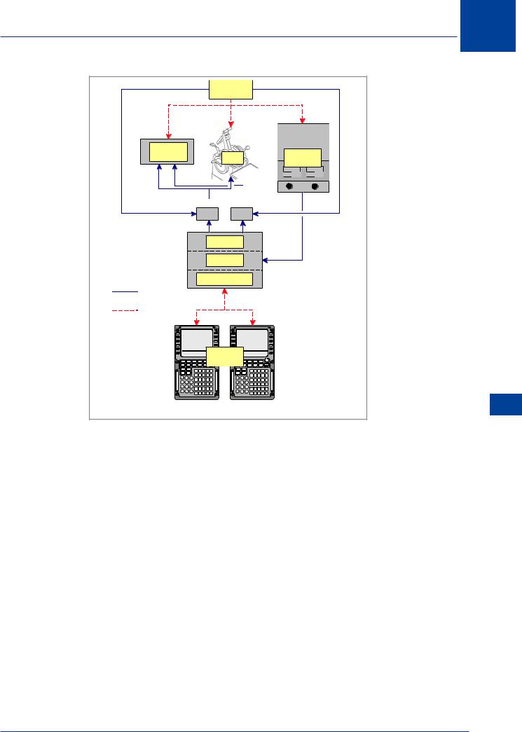
The 737-800 FMS
The 737-800 FMS comprises:
•Flight Management Computer System (FMCS)
•Autopilot/Flight Director System (AFDS)
•Autothrottle (A/T)
•2 Inertial Reference Systems (IRS)
Each component is an independent system which may be used individually or in various combinations. The term FMS implies the joining of all these systems into one integrated system which provides automatic navigation, guidance and performance management. The FMS provides 4D area navigation (latitude, longitude, altitude and time) and optimizes peformance to achieve the most economical flight possible. It provides centralized cockpit control of the aircraft’s flight path and performance parameters.
The Flight Management Computer (FMC) is the heart of the system, performing all the navigational and performance calculations and providing control and guidance commands. A control and display unit (CDU) allows the crew to input the flight details and performance parameters into the FMC. The navigation and performance computations are displayed on the CDU for reference and monitoring. The related FMC commands for lateral (LNAV) and vertical (VNAV) navigation may be coupled to the AFDS and A/T.
In the navigation functions the FMC receives inputs of position and heading from the IRS and fixing information using twin DME. The FMC compares these inputs and by a process known as Kalman filtering produces a system position. In the operation with radio position updating, the FMC is combining the short term accuracy of the IRS with the long term accuracy of the external reference. If the FMS is using just the IRS information to derive position a warning is displayed to the crew indicating that the positional information is downgraded.
The crew may select the level of automation required, from simply using the data displays to fly the aircraft manually, e.g. for heading or TAS/Mach No., to fully automatic flight path guidance and performance control (see Figure 16.5).
Even with full FMS operation, the crew have absolute control of the management and operation of the aircraft. Furthermore, certain functions can only be implemented by the crew, e.g. thrust initiation, take-off, altitude selection, ILS tuning, aircraft configuration and landing rollout. The crew should always monitor the FMC navigation throughout the flight to ensure the flight plan is being accurately followed by the automatic systems.
268
Area Navigation Systems (RNAV) 16
|
|
|
|
|
|
|
PILOTS |
|
|
|
|
|
|||||
AFDS |
|
|
|
|
|
|
A/T |
|
|
|
|
|
|
|
IRSs |
||
|
|
|
|
|
|
|
|
|
|
|
|
|
|
|
|||
|
|
|
|
|
V NAV |
|
L NAV |
|
|
|
|
|
|||||
|
|
|
|
|
|
ON |
|
ON |
|
|
|
|
|
||||
|
|
|
|
|
|
|
COMMANDS |
|
|
|
|
|
|
|
|
||
|
|
|
|
|
|
|
|
FMC |
|
|
|
|
|
|
|
|
|
|
|
|
|
|
|
COMPUTATIONS |
|
|
|
|
|
|
|||||
INTEGRATED |
|
|
|
|
|
|
|
|
|
|
|
|
|
|
|
|
|
FMS OPERATION |
|
|
|
|
|
|
|
|
|
|
|
|
|
||||
INDEPENDENT |
|
|
|
|
|
|
|
|
|
|
|
|
|
|
|
||
OPERATION |
|
|
|
|
|
|
|
|
|
|
|
|
|
|
|
|
|
|
|
|
|
PAGE TITLE |
|
|
|
|
|
|
PAGE TITLE |
|
|
|
|
||
|
|
DATA |
|
|
|
DATA |
|
DATA |
|
|
|
DATA |
|
||||
|
|
DATA |
|
|
|
DATA |
|
DATA |
|
|
|
DATA |
|
||||
|
|
DATA |
|
|
|
DATA |
|
DATA |
|
|
|
DATA |
|
||||
|
|
DATA |
|
|
|
DATA |
|
DATA |
|
|
|
DATA |
|
||||
|
|
DATA |
|
|
|
DATA |
|
DATA |
|
|
|
DATA |
|
|
|||
|
|
PAGE |
SELECT |
PAGE SELE T |
|
PAGE |
SELECT |
|
PAGE SELECT |
|
|||||||
|
INIT |
|
|
|
|
|
|
INIT |
|
|
|
|
|
|
|
|
|
|
REF |
RTE |
CLB |
CRZ |
DES |
CDUsREF |
|
RTE |
CLB |
CRZ |
DES |
|
|
|
|||
|
DIR |
LEGS |
DEP |
HOLD |
PROG |
EXEC |
|
DIR |
|
LEGS |
DEP |
HOLD |
PROG |
EXEC |
|
||
|
INTC |
ARR |
|
|
INTC |
|
ARR |
|
|
|
|||||||
|
MENU |
NAV |
|
|
|
|
|
MENU |
|
NAV |
|
|
|
|
|
|
|
|
RAD |
|
A B C D E |
|
|
RAD |
|
A B C D E |
|
||||||||
|
PREV |
NEXT |
|
M |
PREV |
|
NEXT |
|
M |
||||||||
|
PAGE |
PAGE |
|
F G H I J |
S |
PAGE |
PAGE |
|
F G H I |
J |
S |
||||||
|
1 |
2 |
|
3 |
G |
1 |
2 |
3 |
|
G |
|||||||
|
|
K L |
M N O |
|
|
K L |
M N |
O |
|
||||||||
|
4 |
5 |
|
6 |
|
4 |
5 |
6 |
|
|
|||||||
|
|
P Q R S T |
|
|
P Q R S T |
|
|||||||||||
F |
7 |
8 |
9 |
F |
7 |
8 |
9 |
|
|
||||||||
AI |
U V W X Y |
AI |
|
U V W X Y |
|
||||||||||||
L |
. |
0 |
|
+/- |
L |
. |
0 |
+/- |
|
|
|||||||
|
|
Z . |
DEL |
/ CLR |
|
|
Z . |
DEL |
/ |
CLR |
|
||||||
|
|
|
|
|
|
|
|
|
|
|
|||||||
CONDITION: L NAV AND V NAV ENGAGED |
|||||||||||||||||
|
Figure 16.5 B737 - 400 FMS |
||||||||||||||||
The FMC contains a performance database and a navigation database. The performance database contains all parameters of the aircraft performance and the company’s cost index strategy. The navigation database contains aeronautical information for the planned area of operations of the aircraft, comprising:
•aerodrome details, positions, elevations, runways and lengths etc.
•navigation facilities, including location, altitude, frequency, identification and DOC.
•airways routes, including reporting points.
•SIDs and STARs and runway approaches.
•company routes.
The navigation data is updated every 28 days and the FMC contains the current and next 28 days database (this coincides with the ICAO navigation data cycle). The data may be customized for the specific airline operations.
Area Navigation Systems (RNAV) 16
269
16 Area Navigation Systems (RNAV)
Control and Display Unit (CDU)
The CDU is the means of communication with the FMC. It is used before flight to initialize the performance and navigation requirements for the flight.
(RNAV) Systems Navigation Area 16
|
PAGE TITLE |
|
DATA |
|
DATA |
DATA |
|
DATA |
DATA |
|
DATA |
|
||
DATA |
|
DATA |
DATA |
|
DATA |
|
PAGE SELECT |
|
PAGE SELECT |
|
|||||
|
INIT |
RTE |
|
CLB |
CRZ |
DES |
|
|
|
|
REF |
|
|
|
|
||||
|
|
|
|
|
|
|
|
|
|
|
DIR |
LEGS |
|
DEP |
HOLD |
PROG |
EXEC |
|
|
|
INTC |
|
ARR |
|
|
||||
|
|
|
|
|
|
|
|
||
|
MENU |
NAV |
|
|
|
|
|
|
|
|
RAD |
|
A |
B |
C |
D |
E |
|
|
|
|
|
|
||||||
|
PREV |
NEXT |
|
M |
|||||
|
|
|
|
|
|
|
|||
|
PAGE |
PAGE |
F |
G |
H |
I |
J |
S |
|
|
1 |
2 |
3 |
G |
|||||
|
K |
L |
M |
N |
O |
|
|||
|
4 |
5 |
6 |
|
|||||
|
P |
Q |
R |
S |
T |
|
|||
F |
7 |
8 |
9 |
|
|||||
A |
|
|
|
|
|
|
|||
I |
|
|
|
U |
V |
W X |
Y |
|
|
L |
. |
0 |
+/- |
|
|||||
|
Z |
. |
DEL |
/ |
CLR |
|
|||
|
|
|
|
|
|||||
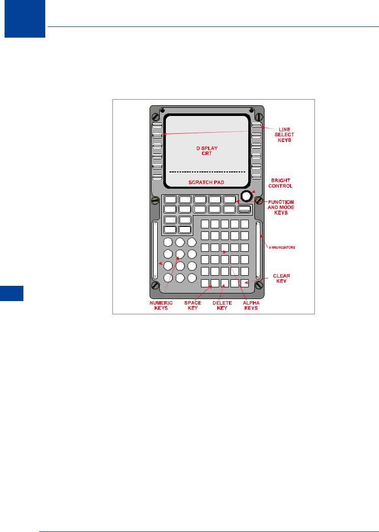
Figure 16.6 Control and display unit
In addition to the alphanumeric keypad and the specific function keys, alongside the display are line select keys (LSK) which are used for inserting or selecting data into the FMC and moving through the various function pages. The format of the display is; in the top field the title of the selected page and, where the selected function has more than one page, the page number (e.g. 1 of 3). In the centre of the display are up to 10 data fields, 5 on the left and right respectively which are accessed using the LSKs. At the bottom of the screen are two or more page select fields and below them the scratchpad. The scratchpad is used to input or modify data for insertion into the appropriate data field.
Pre-flight
The pre-flight initialization of the FMC in the navigation mode requires the pilot to check the validity of the database and input:
•check the correct database installed - IDENT.
•the aircraft position - POS INIT.
•departure and destination aerodromes.
•intended SID and STAR procedures.
•the planned route - POS INIT.
270

Area Navigation Systems (RNAV) 16
If the aircraft is flying a standard company route then the route designator is inserted, otherwise the pilot will have to input the route manually. Data is initially typed into the scratchpad at the bottom of the screen then inserted in the appropriate position using the line selection keys. Once a valid position has been input it is passed to the IRS.
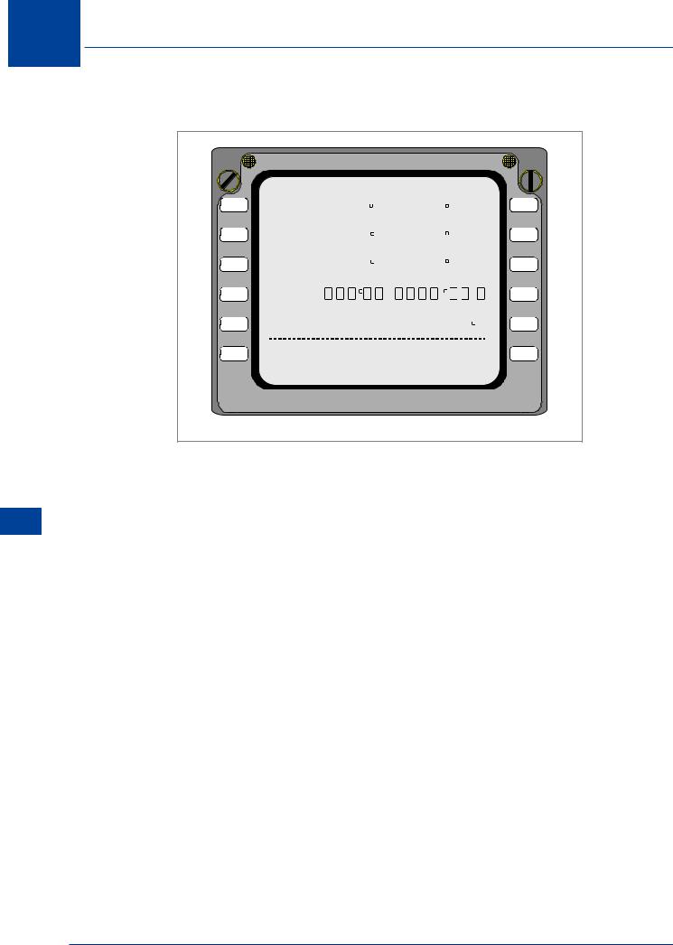
IDENT Page
|
IDENT |
1 / 1 |
|
|
|
|
|
|
|
1L |
M O D E L |
E N G |
R A T I N G |
1R |
737-400 |
|
23.5K |
||
2L |
NA V DA TA |
|
AC TI VE |
2R |
TBC1880101 |
J A N 0 1 J A N 2 8 / 8 9 |
|||
3L |
|
J A N 2 8 F E B 2 5 / 8 9 |
3R |
|
4L |
O P P R O G R A M |
|
|
4R |
548925-08-01 |
(U5.0) |
|
||
|
|
|
||
5L |
|
S U |
P P D A T A |
5R |
|
J A N 2 1/88 |
|||
6L |
<INDEX |
POS INIT > |
6R |
|
Figure 16.7
When power is applied, the FMS executes an internal test sequence. When the test is successfully completed, it presents the IDENT page on the CDU. This page contains information on the aircraft model and engine thrust from the performance database at 1L and 1R, the identification of the permanent navigation database at 2L with 2R and 3R showing the currency periods of the navigation data in the database. At 4L is the identification of the operating programme and at 5R is the date of the supplementary data. The only information that can be changed on this display is the current nav data at 2R. If this is out of date a prompt will appear in the scratchpad. To change the data, select LSK 3R to downselect the next period of data to the scratchpad, then 2R to insert the data into the active data line. Note that at 6R is the prompt for the next page in the initialization sequence and at 6L is the prompt for the page index. Where any input data is used on other CDU pages the data will automatically ‘propagate’ to those pages.
Area Navigation Systems (RNAV) 16
271
16 Area Navigation Systems (RNAV)
(RNAV) Systems Navigation Area 16
POS INIT Page
|
|
POS INIT |
|
1 / 3 |
|
|
||
1L |
|
|
|
L A S T |
P O S |
1R |
||
|
N47 |
32.4 |
W122 |
18.7 |
|
|||
|
|
|
|
|||||
2L |
R E F A I R P O R T |
|
|
|
|
|
2R |
|
KBFI |
N47 |
31.8 |
W122 |
18.0 |
|
|||
|
G A T E |
|
|
|
|
|
|
|
3L |
BF21 |
N47 |
31.1 |
W122 |
18.2 |
|
3R |
|
|
|
|
|
S E T I R S |
P O S |
|
||
4L |
|
|
. |
|
|
. |
|
4R |
5L |
G M T - M O N / D Y |
|
S E T I R S H D G |
5R |
||||
1432.2 Z |
09/20 |
|
|
--- |
|
|||
6L |
<INDEX |
|
|
ROUTE |
> |
6R |
||
Figure 16.8
The position initialization (POS INIT) page allows initialization of heading and position for the IRS. On all displays the dashed lines, as at 5R, indicate where optional data may be inserted to assist the FMC operation. The boxed areas at 4R indicate where data essential to the operation of the FMC must be inserted. The last position recorded before shutdown is displayed at 1R. The departure airport is inserted at 2L and the gate at 3L. The FMC extracts the airfield reference and gate positions from the database and inserts them at 2R and 3R respectively. At 4R the FMC is asking for the aircraft position to initialize the IRS. The position could be input manually in the scratchpad then inserted by selecting LSK 4R. However, the database has already inserted the position into 3R, so this can be copied by selecting 3R to draw the data down to the scratchpad and then 4R to insert into the field. To speed up alignment, particularly if the aircraft has been moved, the magnetic heading from the standby compass can be input at 5R. Having completed this, the alignment of the IRS will now proceed. The prompt at 6R now directs the pilot to the route (RTE) page.
272

Area Navigation Systems (RNAV) 16
RTE Page
The route pages are used to insert, check and/or modify a company route, or to insert a route not held in the database.
|
RTE |
1 / XX |
|
|
1L |
O R I G I N |
D E S T |
1R |
|
KBFI |
KMWH |
|||
|
|
|||
2L |
C O R O U T E |
F L T N O |
2R |
|
BFIMWH |
430 |
|||
|
R U N W A Y |
|
|
|
3L |
13R |
|
3R |
|
4L |
V I A |
T O |
4R |
|
LACRE3 . VAMPS |
VAMPS |
|||
5L |
V2 |
ELN |
5R |
|
6L |
|
ACTIVATE > |
6R |
Figure 16.9
The departure and destination aerodromes are input to 1L and 1R respectively. Valid data is any ICAO aerodrome designator held in the database. If the ICAO identifier was input on the POS INIT, then it will appear at 1L. The company route is inserted at 2L and the flight number at 2R. The runway in use and the SID and first route waypoint are inserted at 3L and 4L. Note this will automatically appear if they are defined in the company route. The information at 5L (airway) and 5R (next reporting point on airway V2) is inserted by the computer from the database. To access the subsequent pages of the RTE, select the NEXT PAGE function key on the keyboard to check or modify the route. The 6R prompt directs the pilot to activate the route. Pressing 6R will illuminate the EXEC key on the CDU which should in turn be pressed for the computer to action the route after take-off. After take-off the RUNWAY line is cleared and the VIA/TO moves up to line 3 and the next waypoint appears at 4. As an active waypoint is passed, line three is cleared and replaced with the next active waypoint.
The pre-flight actions for the navigation profile are now complete, but the performance initialization is yet to be actioned. This is dealt with elsewhere in the course. The computer will check the conditions against the performance data and the required cost index profile and inform the pilots of the power, speed and configuration to achieve the required profile. If a manual input of a route is required, this can be achieved through the scratchpad, as can any modifications to the standard company routes.
The valid formats for navigational inputs are:
Latitude and Longitude as either a 7 group alphanumeric (e.g. N05W010) or a 15 group (e.g. N0926.3W00504.7). Note the leading zeros must be entered for the FMC to accept the position.
Up to 5 alphanumerics for ICAO aerodrome designators, reporting points, navigation facilities, airways designators (e.g. EGLL, KODAP, DHD, A23) and runway designators.
Area Navigation Systems (RNAV) 16
273

16
(RNAV) Systems Navigation Area 16
Area Navigation Systems (RNAV)
Up to 7 alphanumerics for SID and STAR (e.g. TURN05).
Range and bearing from a navigational aid or reporting point (e.g. TRN250.0/76). Note the decimals are optional, the bearing must always be a 3 or 5 digit group, the distance may be 1 to 5 digits. In this case the FMC would give the position the designation TRN01, assuming it was the first or only position specified with reference to TRN. These are known as place bearing/ distance (PBD) waypoints.
TRN |
250/76 |
TRN01 |
Figure 16.10 Range/bearing waypoint
Course interception waypoints are positions defined where the bearing from any valid database position intersects with a course (e.g. an airway) or the bearing from another database defined position. The format for input is e.g. GOW167.0/TRN090.5, the FMC now produces a PBD waypoint which in this case would be designated GOW01. As above the bearings must be either 3 or 5 digits.
 GOW
GOW
 180
180
090.5  TRN
TRN 


GOW01
Figure 16.11 Bearing/bearing waypoint
274