


8 VHF Omni-directional Range (VOR)
(VOR) Range directional-Omni VHF 8
There are a few other aspects of deviation indicators which are worth mentioning. Firstly, if the instrument has an ILS glide path needle, this needle will be inoperative, centralized, and flagged ‘OFF’ when the indicator is being used to display VOR information. Conversely, when ILS information is being displayed, the OBS is inoperative and the TO/FROM indication is meaningless.
Radio Magnetic Indicator (RMI)
The RMI provides an alternative means of presenting VOR bearing information and it has been described at some length in the ADF notes. Briefly, it has a remote-reading compass repeater card which indicates the aircraft’s magnetic heading against a fixed heading index at the top of the instrument.
A pointer indicates on the compass card the aircraft’s QDM to the beacon. (Two needles are common so that two bearings can be simultaneously displayed). Students for professional licences should note that before display on the RMI, VOR information must be processed differently from ADF information. This is because the aircraft receives a magnetic bearing from the VOR ‘dispensed’ in the form of a phase difference, whereas the ADF equipment gives a direct indication of relative bearing.
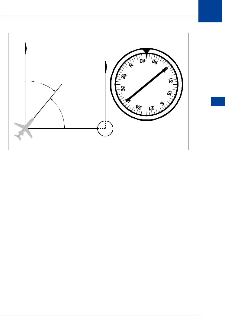
The VOR QDM derived from the measured phase difference between the reference and variphase signals is converted to a relative bearing for display on the RMI. (This is achieved by means of a ‘differential synchro’ which automatically subtracts the aircraft’s magnetic heading from the VOR QDM). The resulting relative bearing positions the RMI needle, the point of which, however, indicates the original QDM to the VOR because the magnetic heading which was subtracted is in effect re-applied by the compass repeater card. If the QDM to the VOR shown on the RMI is to be converted to a True bearing for plotting, the variation at the VOR station must be applied.
As an example of the above, and with reference to Figure 8.12, suppose the aircraft heading is 040°(M) and the measured phase difference is 270°. The equipment derives from the latter a QDM of 090° and subtracts the heading of 040° to give a relative bearing of 050° which positions the RMI needle 50° clockwise from the heading index. (If there were a difference in variation between the positions of the aircraft and VOR station, this derived relative bearing would have a corresponding error but the QDM indicated by the needle would still be correct). Continuing with the example, the RMI heading index reads 040° and the needle indicates 040° + 050° = 090°, which is the correct QDM to the VOR based on the magnetic meridian at the beacon. Compare this with the case of an ADF bearing displayed by RMI, where the magnetic bearing indicated is based on the magnetic variation at the aircraft.
One useful aspect of RMI presentation deserves mention. The arrowhead of the needle shows the QDM of the beacon, so consequently the ‘tail’ end of this full-diameter pointer indicates the reciprocal of the QDM, that is, the radial on which the aircraft is positioned. Thus both the bearing TO and the bearing FROM the station are clearly displayed.
It is worthwhile making a comparison between the RMI and the OBS type deviation indicator. The RMI has certain disadvantages in that it is a more complex instrument requiring additional hardware, including a remote-reading magnetic compass and the appropriate power supplies. It is therefore heavier, occupies more space and is more costly.
122
VHF Omni-directional Range (VOR) 8
N(M) |
HEADING |
|
|
INDEX |
|
N(M) |
|
|
040°(M) |
|
|
050° REL |
|
|
270 RADIAL |
BEACON |
|
090 QDM |
||
|
||
(PHASE DIFFERENCE 270°) |
|
Figure 8.12 VOR QDM on the RMI
In large aircraft these disadvantages are outweighed by the following advantages:
•The RMI provides continuous indication of the QDM to a VOR (and the reciprocal of the QDM, the radial, at the tail of the pointer).
•Magnetic heading is also displayed, on the same instrument; a considerable asset when homing to a VOR or maintaining a track outbound.
•The approximate relative bearing of a beacon is immediately apparent, a ‘plan view’ of the local navigation situation being presented; this is most useful when flying a holding procedure.
•As the pointer automatically gives a continuous indication of the VOR bearing, the rate of crossing radials during interception of a radial is easily assessed.
•With two-needle RMIs, the bearings of two beacons can be simultaneously displayed which is particularly useful when flying along an airway using one beacon ahead (or astern) for track-keeping, and a second beacon off the airway for reporting abeam.
•ADF bearings can be displayed on an RMI.
VHF Omni-directional Range (VOR) 8
123
8 VHF Omni-directional Range (VOR)
(VOR) Range directional-Omni VHF 8
VOR - Displays
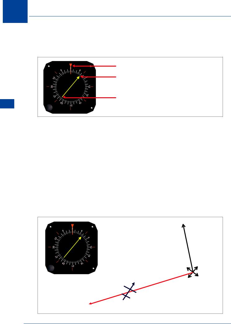
RMI (Radio Magnetic Indicator)
Aircra Heading 030° (Compass / Magnetic)
QDM – Arrowhead 070°
QDR – Tail of Needle 250°
Figure 8.13
Heading displayed will always be Compass Heading, which should be very close (deviation) to Magnetic Heading.
The VOR QDR/QDM displayed will be the Radial that the aircraft is actually on. (For examination purposes; If the arrowhead and the tail do not agree, due to a bent needle, then the arrowhead will be the correct reading)
The arrowhead will always point TO the beacon QDM.
The aircraft’s heading will not affect the readings.
If heading is correct then both Relative Bearing and Radial will be correct.
If heading is in error then the Radial will be correct but the Relative Bearing will be wrong.
No action is required by the pilot.
Magnetic
North
Aircra |
|
Heading |
VOR |
030°(M) |
|
|
Beacon |
250°(M) Radial
From VOR
QDR
Figure 8.14
124
VHF Omni-directional Range (VOR) 8
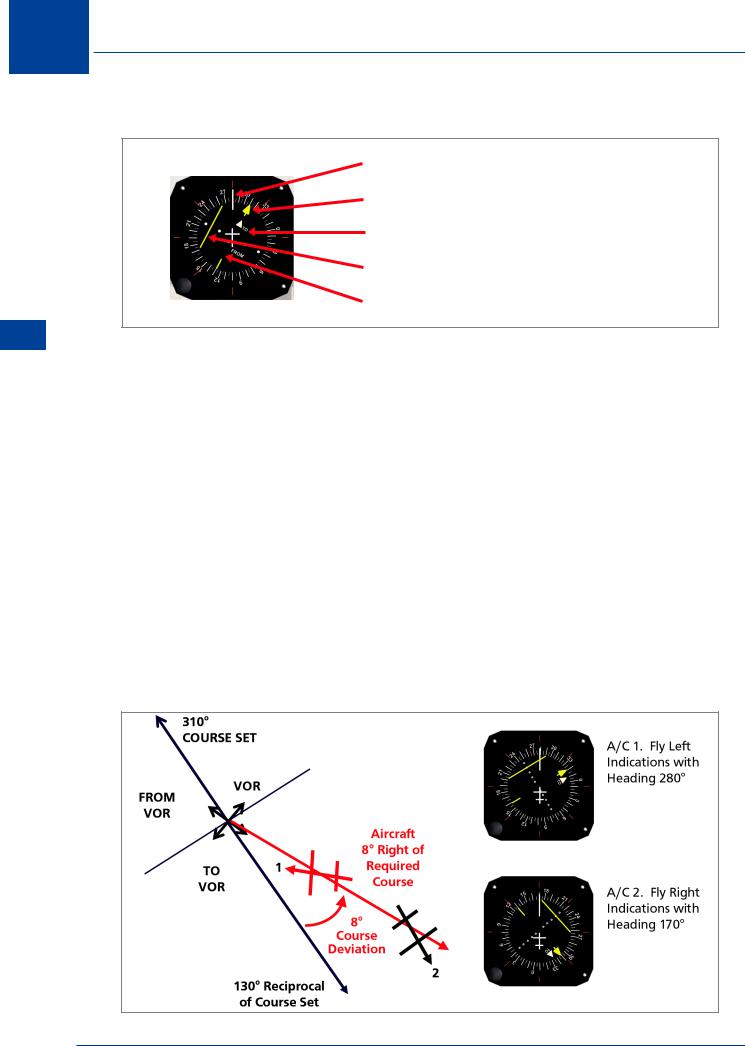
CDI (Course Deviation Indicator)
Selected / Required Course
 TO Beacon (Selected)
 FROM Beacon (De-selected)
Course Deviation Bar (6° Fly Le )
Figure 8.15
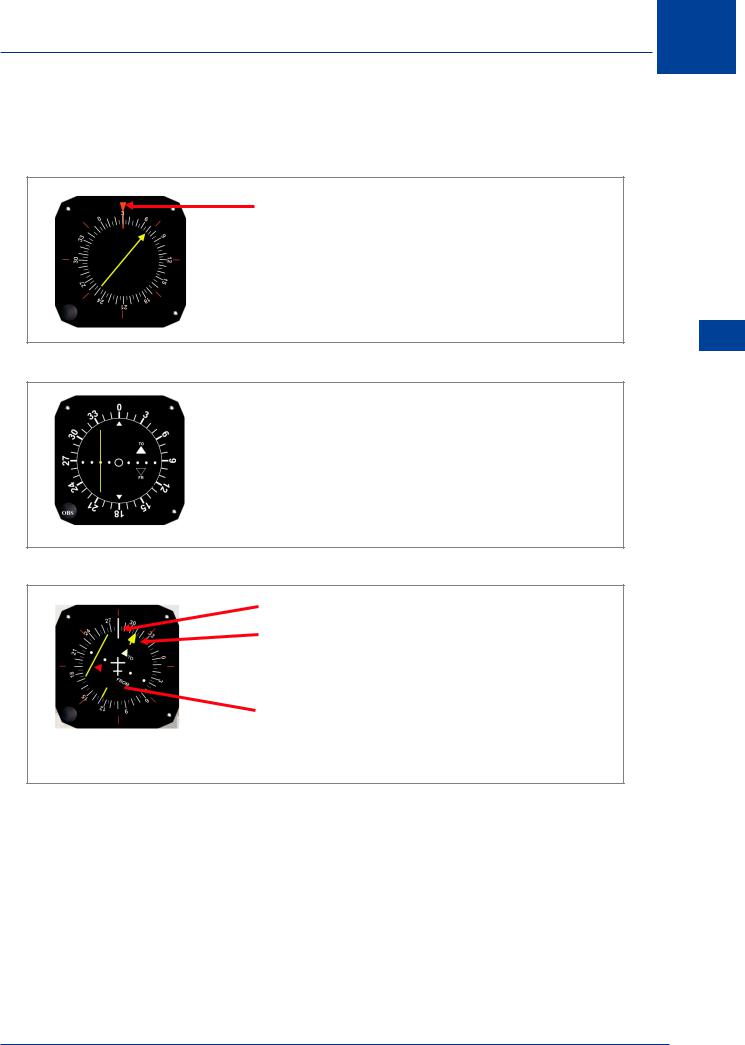
Course shown at top/centre of the dial is the Required Course to fly to achieve the desired aim.
The TO/FROM indicator will be decided by the instrument. If the actual radial, which the aircraft is on, is within 90° of the Set Course then FROM will be shown. If the actual radial, which the aircraft is on, is more than 90° from the Set Course then TO will be shown.
The Course Deviation Bar shows the angular difference between the Required Course and the actual VOR Radial the aircraft is on.
1 Dot = 2° |
Full Scale Deflection = 10° |
The edge of the inner circle is the first dot = 2°
The aircraft’s heading will not affect the readings.
The pilot sets the Required Course, using the OBS knob.
Figure 8.16
VHF Omni-directional Range (VOR) 8
125
8 VHF Omni-directional Range (VOR)
(VOR) Range directional-Omni VHF 8
HSI (Horizontal Situation Indicator)
Aircra Heading 280° (Compass / Magnetic)
Selected / Required Course
TO Beacon (Selected)
Course Deviation Bar (8° Fly Le )
FROM Beacon (De-selected)
Figure 8.17
Heading displayed will always be Compass Heading, which should be very close (deviation) to Magnetic Heading.
The arrowhead shows the Required Course, set by the pilot.
The TO/FROM indicator will be decided by the instrument. If the actual radial, which the aircraft is on, is within 90° of the Set Course then FROM will be shown. If the actual radial is more than 90° from the Set Course then TO will be shown.
The Course Deviation Bar shows the angular difference between the Required Course and the actual VOR Radial the aircraft is on.
1 Dot = 5° |
Full Scale Deflection = 10° |
An HSI may be either a 2 Dot or 5 Dot display
Full Scale Deflection will always be 10°. 2 Dot: display 1 dot = 2°. 5 Dot display: 1 Dot = 5°
Aircraft heading is taken into consideration in displaying a fly left or fly right indication. However, as the instruments includes heading, it is able to determine the best direction to turn to achieve the required radial. So it is possible to be right of the radial but to be given a turn right indication.
Figure 8.18
126
VHF Omni-directional Range (VOR) 8
Summary
RMI
Aircra Heading 030° (Compass / Magnetic)
 QDM – Arrowhead 070°
 QDR – Tail of Needle 250°
Aircra ’s Heading is NOT Relevant
CDI
 Selected / Required Course
 TO Beacon (Selected)
 FROM Beacon (De-selected)
 Course Deviation Bar (6° Fly Le )
Aircra ’s Heading is NOT Relevant
HSI
Aircra Heading 280° (Compass / Magnetic)
Selected / Required Course
 TO Beacon (Selected)
 Course Deviation Bar (8° Fly Le )
FROM Beacon (De-selected)
Aircra ’s heading will determine
Turn Le / Turn Right Indication
VHF Omni-directional Range (VOR) 8
127