


Radar Principles 11
The Range of Primary Radar
Maximum Range
The range of a primary radar depends upon the strength of the returning pulses that determines the quality of the target depiction on the PPI. The range is affected by several factors:
• Transmission power. A radar signal attenuates with increasing distance from the transmitter.
|
As the signal has to travel out and back the power/range relationship is: |
|
|||||||||||||||||||
|
Power available is proportional to the fourth power of range which means that the power |
|
|||||||||||||||||||
|
has increased by a factor of 16 to double the range |
|
|
|
|
|
|
|
|
||||||||||||
• |
Characteristics of reflecting objects. Metals are more efficient than wood at reflecting |
|
|||||||||||||||||||
|
the transmitted signal and the size and shape of the detected object make a considerable |
|
|||||||||||||||||||
|
difference to the effective range. The aspect of the object also affects the range; for |
|
|||||||||||||||||||
|
instance, a manoeuvring aircraft presents various aspects which can affect the polarization |
|
|||||||||||||||||||
|
of reflected waves. The side of the fuselage has a better aspect than the nose of the aircraft. |
|
|||||||||||||||||||
• |
Aircraft height and the height of the radar head. |
Radar transmissions, because of their |
11 |
||||||||||||||||||
|
|||||||||||||||||||||
|
frequency bands, travel in straight lines and give line of sight ranges, plus a little extra due |
Principles |
|||||||||||||||||||
|
to atmospheric refraction. Thus the curvature of the earth causes much of the surface to |
||||||||||||||||||||
|
be in shadow. Therefore, higher flying aircraft are more likely to be detected because they |
||||||||||||||||||||
|
are above that shadow. Intervening high ground also will screen low flying aircraft from |
Radar |
|||||||||||||||||||
|
detection. The higher the radar head can be positioned, the greater that radar’s range and |
||||||||||||||||||||
|
|
||||||||||||||||||||
|
the less effect intervening high ground will have on stopping signals and reducing its range. |
|
|||||||||||||||||||
|
The following formula can be used to calculate the maximum theoretical radar range: |
|
|||||||||||||||||||
|
|
|
|
|
|
|
|
= |
1.23 |
|
× (√ |
|
|
|
|
|
|
|
|
|
|
|
Max. Theoretical range (NM) |
HTX + √ |
HRX) |
|
|
|
|
||||||||||||||
|
HTX = height of radar station in feet AMSL; |
HRX = height of target in feet AMSL. |
|
||||||||||||||||||
• |
Wavelength and attenuation by raindrops |
|
|
|
|
|
|
|
|
|
|
||||||||||
|
|
|
|
|
|
|
|
|
|
|
|
|
|
|
|
|
|
|
|
|
|
|
100 |
|
|
|
|
|
|
|
|
|
|
|
|
|
|
|
|
||||
|
|
|
|
|
|
|
|
|
|
|
|
|
|
|
|
|
|||||
|
|
|
|
|
|
|
|
|
|
|
|
|
|
|
|
|
|||||
|
80 |
|
|
|
|
|
|
|
|
|
|
|
|
|
|
|
|
||||
|
|
|
|
|
|
|
|
|
|
|
|
|
|
|
|
|
|||||
|
|
|
|
60 |
|
|
|
|
|
|
|
|
|
|
|
|
|
|
|
|
|
|
|
|
|
|
|
|
|
|
|
|
|
|
|
|
|
|
|
|
|
||
|
|
|
|
|
|
|
|
|
|
|
|
|
|
|
|
|
|
|
|
||
|
|
|
|
|
40 |
|
|
|
|
|
|
|
|
|
|
|
|
|
|
|
|
|
|
|
|
|
|
|
|
|
|
|
|
|
|
|
|
|
|
|
|
|
|
|
|
|
|
|
|
|
|
|
|
|
|
|
|
|
|
|
|
|
|
|
|
|
|
|
|
|
|
|
|
|
|
|
|
|
|
|
|
|
|
|
|
|
|
|
|
|
|
|
|
|
|
|
|
|
|
|
|
|
|
|
|
|
|
|
|
|
|
|
|
|
|
|
|
|
|
|
|
|
|
|
|
|
|
|
|
|
|
|
20 |
|
|
|
|
|
|
|
|
|
|
|
|
|
|
|
|
||||
|
|
|
|
|
|
|
|
|
|
|
|
|
|
|
|
|
|||||
|
0 |
|
|
|
|
|
|
|
|
|
|
|
|
|
|
|
|
||||
|
|
|
|
|
|
|
|
|
|
|
|
|
|
|
|
|
|||||
|
0.03 |
0.1 |
0.3 |
1 |
3 |
|
10 |
|
|
||||||||||||
λ(cm) LOGARITHMIC SCALE
Figure 11.6 Attenuation by raindrops
189

11 Radar Principles
Principles Radar 11
It can be seen from Figure 11.6 that energy is absorbed and scattered by raindrops; the total effect depends upon the size of the water droplets and the transmitted wavelengths. At wavelengths longer than 10 cm the attenuation is negligible. If the wavelength is between 10 cm and 4 cm the attenuation is significant only in tropical rain. However, with wavelengths less than 4 cm, attenuation is significant in rain in the temperate latitudes. One conclusion is that wavelengths less than 3 cm should not be used for long range systems. Airfield Surface Movement Indicator (ASMI) radars operate at 1.75 to 2 cm wavelengths. Airborne Weather Radars (AWR) and Precision Approach Radars (PAR) use 3 cm wavelengths. Surveillance radars (ground) use 10, 23 or 50 cm wavelengths.
•Atmospheric conditions. Certain atmospheric conditions can actually increase the range of radar pulses by refracting the waves which would normally travel in straight lines. This is called super-refraction and it gives radar ranges beyond normal line of sight i.e. it gives over the horizon radar capability by causing the radio waves to refract downwards towards the earth’s surface. Such conditions occur when there is a temperature inversion and a decrease in humidity with height. On the other hand, atmospheric conditions can also
cause sub-refraction in which the theoretical range of the radar is reduced by causing the waves to refract upwards away from the surface.
+
0  TIME
TIME
- |
|
|
W |
PULSE |
W |
|
|
|
|
|
|
||
|
|
|
WIDTH |
|||
+ |
|
|
|
|
|
|
|
|
|
|
|
|
|
0 |
|
|
|
|
|
TIME |
- |
|
|
|
W = PULSE WIDTH |
||
|
|
|
RADIO WAVES TRAVEL 300 000 000 M/S |
|||
|
|
|
|
|||
|
|
|
|
IN 1 µS THEY TRAVEL 300 METRES |
||
Figure 11.7 Pulse Width Decides Minimum Range
•Restoration Time is a design factor that affects the time taken for a receiver to recover to normal after transmission has occurred.
•Pulse width determines the minimum range. With reference to Figure 11.7, it can be shown that a pulse 1 µs wide would extend 300 metres. Thus an object at 150 metres reflecting this pulse would cause it to arrive back at the receiver as its tail was leaving the transmitter.
Any object closer than 150 metres would reflect a pulse that could not be received as the transmitter would still be transmitting. Furthermore, two objects in line 150 metres or less apart would appear as a single return. As a result, if short range operation is required for target resolution and accuracy, short pulses are used, e.g. 0.1 µs.
190

Radar Principles
Note: 1 or 2 µs are used for medium range radars and about 5 µs for long range radar.
Question A surface movement radar is required to measure down to 500 m. Calculate the maximum pulse width in microseconds.
Answer |
3.3 µs |
Radar Measurements
Bearing
Bearing measurement is obtained by using the searchlight principle. Radio pulses are concentrated into very narrow beams which are produced by shortening the wavelength or increasing the aerial size and in advanced systems this is done electronically. The beam is rotated at a constant speed. The PPI display is synchronized with the antenna rotation. The direction of an object is the direction of the beam, measured from a fixed datum, at the time when the echo is received.
Range
Calculated from the time interval between the transmission and reception of the radar pulse.
Harmonization
In order that bearing and range information can be determined from the radar system it is necessary to harmonize the rotary speed of the antenna, the pulse duration or width, the pulse repetition frequency, focusing and transmission power.
Radar Resolution
The image painted on a PPI display from a point target will not be a single point but will appear as a rectangle, known as the radar resolution rectangle i.e. the target appears to be stretched both radially and in azimuth. The dimensions of the rectangle depend upon the pulse length, the beamwidth and the spot size.
The radial resolution is dependent upon half the pulse length. For example, a pulse length of 1 μs would stretch the target by 150 metres (distance that an electromagnetic wave travels in 0.5 µs). If two targets happen to be within half pulse width they will be illuminated simultaneously by the pulse and return only a single echo to the receiver.
The azimuth resolution is dependent upon the full beamwidth. Therefore a 3° beamwidth at a range of 120 km would stretch the target in azimuth by 6 km (using the 1 in 60 rule).
It follows therefore that in order to resolve adjacent targets the radar should have short pulse lengths and narrow beamwidths. However shortening the pulse length reduces the time the target is illuminated by the pulse and reduces the chance of a good return being received. Beamwidths can only be narrowed by increasing the size of the antenna.
The spot size and the target size also increase the size of the echo displayed on the PPI screen.
Moving Target Indication (MTI)
Surveillance radar equipment incorporates circuitry designed to eliminate returns from stationary objects such as hills or buildings which would give returns that would mask the smaller returns from aircraft. By erasing the permanent echoes the radar is able to display only the moving targets such as aircraft.
11
Radar Principles 11
191
11 Radar Principles
It is possible for a radar receiver on MTI to produce false targets as a result of second trace returns i.e. a return of the preceding pulse from a target beyond the maximum range selected, appearing during the period of the next pulse as a moving target within the selected range. In order to overcome this problem, MTI radars remove second trace returns by changing the PRI between consecutive pulses, a technique known as ‘jittering the PRF’.
Radar Antennae
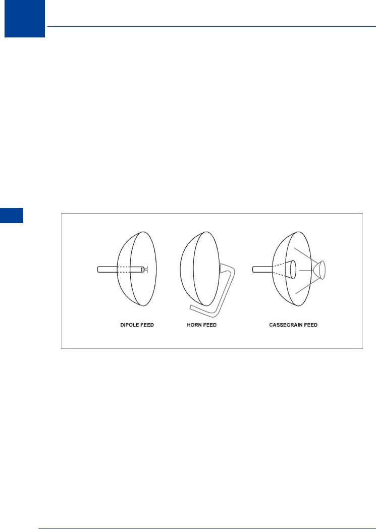
The microwave horn, parabolic reflector and slotted planar array (or flat plate antenna) shown in Figure 11.8 and Figure 11.9 are popular antennae which are used extensively in radar and satellite systems. Microwave horns are very often used as feeds for large parabolic reflectors. Both the parabolic reflector and the flat plate antennae generate main lobes as well as side lobes. Most radars will incorporate circuits for side lobe suppression so that echoes from the side lobes do not interfere with the main pulse returns. Figure 11.10 shows a radiation pattern with the main and side lobes of a parabolic reflector. The slotted planar array produces a narrower beam with much smaller side lobes hence reducing the power required and improving the resolution.
Principles Radar 11
Figure 11.8 Radar antennae
192

Radar Principles 11
Figure 11.9 Airborne weather radar antenna
Radar Principles 11
Figure 11.10 Typical radiation pattern
193