

- •Textbook Series
- •Contents
- •1 Properties of Radio Waves
- •Introduction
- •The Radio Navigation Syllabus
- •Electromagnetic (EM) Radiation
- •Polarization
- •Radio Waves
- •Wavelength
- •Frequency Bands
- •Phase Comparison
- •Practice Frequency (
- •Answers to Practice Frequency (
- •Questions
- •Answers
- •2 Radio Propagation Theory
- •Introduction
- •Factors Affecting Propagation
- •Propagation Paths
- •Non-ionospheric Propagation
- •Ionospheric Propagation
- •Sky Wave
- •HF Communications
- •Propagation Summary
- •Super-refraction
- •Sub-refraction
- •Questions
- •Answers
- •3 Modulation
- •Introduction
- •Keyed Modulation
- •Amplitude Modulation (AM)
- •Single Sideband (SSB)
- •Frequency Modulation (FM)
- •Phase Modulation
- •Pulse Modulation
- •Emission Designators
- •Questions
- •Answers
- •4 Antennae
- •Introduction
- •Basic Principles
- •Aerial Feeders
- •Polar Diagrams
- •Directivity
- •Radar Aerials
- •Modern Radar Antennae
- •Questions
- •Answers
- •5 Doppler Radar Systems
- •Introduction
- •The Doppler Principle
- •Airborne Doppler
- •Janus Array System
- •Doppler Operation
- •Doppler Navigation Systems
- •Questions
- •Answers
- •6 VHF Direction Finder (VDF)
- •Introduction
- •Procedures
- •Principle of Operation
- •Range of VDF
- •Factors Affecting Accuracy
- •Determination of Position
- •VDF Summary
- •Questions
- •Answers
- •7 Automatic Direction Finder (ADF)
- •Introduction
- •Non-directional Beacon (NDB)
- •Principle of Operation
- •Frequencies and Types of NDB
- •Aircraft Equipment
- •Emission Characteristics and Beat Frequency Oscillator (BFO)
- •Presentation of Information
- •Uses of the Non-directional Beacon
- •Plotting ADF Bearings
- •Track Maintenance Using the RBI
- •Homing
- •Tracking Inbound
- •Tracking Outbound
- •Drift Assessment and Regaining Inbound Track
- •Drift Assessment and Outbound Track Maintenance
- •Holding
- •Runway Instrument Approach Procedures
- •Factors Affecting ADF Accuracy
- •Factors Affecting ADF Range
- •Accuracy
- •ADF Summary
- •Questions
- •Answers
- •8 VHF Omni-directional Range (VOR)
- •Introduction
- •The Principle of Operation
- •Terminology
- •Transmission Details
- •Identification
- •Monitoring
- •Types of VOR
- •The Factors Affecting Operational Range of VOR
- •Factors Affecting VOR Beacon Accuracy
- •The Cone of Ambiguity
- •Doppler VOR (DVOR)
- •VOR Airborne Equipment
- •VOR Deviation Indicator
- •Radio Magnetic Indicator (RMI)
- •Questions
- •In-flight Procedures
- •VOR Summary
- •Questions
- •Annex A
- •Annex B
- •Annex C
- •Answers
- •Answers to Page 128
- •9 Instrument Landing System (ILS)
- •Introduction
- •ILS Components
- •ILS Frequencies
- •DME Paired with ILS Channels
- •ILS Identification
- •Marker Beacons
- •Ground Monitoring of ILS Transmissions
- •ILS Coverage
- •ILS Principle of Operation
- •ILS Presentation and Interpretation
- •ILS Categories (ICAO)
- •Errors and Accuracy
- •Factors Affecting Range and Accuracy
- •ILS Approach Chart
- •ILS Calculations
- •ILS Summary
- •Questions
- •Answers
- •10 Microwave Landing System (MLS)
- •Introduction
- •ILS Disadvantages
- •The MLS System
- •Principle of Operation
- •Airborne Equipment
- •Question
- •Answer
- •11 Radar Principles
- •Introduction
- •Types of Pulsed Radars
- •Radar Applications
- •Radar Frequencies
- •Pulse Technique
- •Theoretical Maximum Range
- •Primary Radars
- •The Range of Primary Radar
- •Radar Measurements
- •Radar Resolution
- •Moving Target Indication (MTI)
- •Radar Antennae
- •Questions
- •Answers
- •12 Ground Radar
- •Introduction
- •Area Surveillance Radars (ASR)
- •Terminal Surveillance Area Radars
- •Aerodrome Surveillance Approach Radars
- •Airport Surface Movement Radar (ASMR)
- •Questions
- •Answers
- •13 Airborne Weather Radar
- •Introduction
- •Component Parts
- •AWR Functions
- •Principle of Operation
- •Weather Depiction
- •Control Unit
- •Function Switch
- •Mapping Operation
- •Pre-flight Checks
- •Weather Operation
- •Colour AWR Controls
- •AWR Summary
- •Questions
- •Answers
- •14 Secondary Surveillance Radar (SSR)
- •Introduction
- •Advantages of SSR
- •SSR Display
- •SSR Frequencies and Transmissions
- •Modes
- •Mode C
- •SSR Operating Procedure
- •Special Codes
- •Disadvantages of SSR
- •Mode S
- •Pulses
- •Benefits of Mode S
- •Communication Protocols
- •Levels of Mode S Transponders
- •Downlink Aircraft Parameters (DAPS)
- •Future Expansion of Mode S Surveillance Services
- •SSR Summary
- •Questions
- •Answers
- •15 Distance Measuring Equipment (DME)
- •Introduction
- •Frequencies
- •Uses of DME
- •Principle of Operation
- •Twin Pulses
- •Range Search
- •Beacon Saturation
- •Station Identification
- •VOR/DME Frequency Pairing
- •DME Range Measurement for ILS
- •Range and Coverage
- •Accuracy
- •DME Summary
- •Questions
- •Answers
- •16 Area Navigation Systems (RNAV)
- •Introduction
- •Benefits of RNAV
- •Types and Levels of RNAV
- •A Simple 2D RNAV System
- •Operation of a Simple 2D RNAV System
- •Principle of Operation of a Simple 2D RNAV System
- •Limitations and Accuracy of Simple RNAV Systems
- •Level 4 RNAV Systems
- •Requirements for a 4D RNAV System
- •Control and Display Unit (CDU)
- •Climb
- •Cruise
- •Descent
- •Kalman Filtering
- •Questions
- •Appendix A
- •Answers
- •17 Electronic Flight Information System (EFIS)
- •Introduction
- •EHSI Controller
- •Full Rose VOR Mode
- •Expanded ILS Mode
- •Full Rose ILS Mode
- •Map Mode
- •Plan Mode
- •EHSI Colour Coding
- •EHSI Symbology
- •Questions
- •Appendix A
- •Answers
- •18 Global Navigation Satellite System (GNSS)
- •Introduction
- •Satellite Orbits
- •Position Reference System
- •The GPS Segments
- •The Space Segment
- •The Control Segment
- •The User Segment
- •Principle Of Operation
- •GPS Errors
- •System Accuracy
- •Integrity Monitoring
- •Differential GPS (DGPS)
- •Combined GPS and GLONASS Systems
- •Questions
- •Answers
- •19 Revision Questions
- •Questions
- •Answers
- •Specimen Examination Paper
- •Appendix A
- •Answers to Specimen Examination Paper
- •Explanation of Selected Questions
- •20 Index

Electronic Flight Information System (EFIS) 17
EHSI Symbology
The symbology used in the B737-800 is depicted in the following table, which should be used in conjunction with the displays shown in Figures at 17.2 to 17.7. Detailed knowledge of these symbols is not required for the EASA ATPL examinations.
Symbol |
Name |
Applicable |
Remarks |
|
|
Modes |
|
200 NM |
Distance Display |
ALL |
Distance is displayed to next FMC |
(W) |
|
Waypoint (NM) or tuned |
|
or |
|
||
|
|
Navaid (DME). Below 100 NM tenths |
|
DME 124 |
|
|
|
|
|
of a NM will be displayed |
|
|
|
|
|
|
HEADING |
ALL |
Indicates number under pointer is a |
|
Orientation (G) |
|
heading - box indicates actual |
|
Indicator (W) |
|
heading. Referenced to Magnetic (M) |
|
Reference (G) |
|
or true (TRU) North. |
0835.4z |
ETA Display |
PLAN, MAP |
Indicates FMC computed ETA for the |
|
(W) |
|
active waypoint. |
|
Expanded |
PLAN, MAP |
Compass Data is provided by the |
|
Compass |
VOR, ILS |
selected IRS (360° available but |
|
Rose (W) |
|
approximately 70° are displayed |
|
Full Compass |
Full VOR, |
Compass Data is provided by the |
|
Rose (W) |
Full ILS |
selected IRS. |
|
|
|
|
Aeroplane |
EXP |
Represents the aeroplane and |
|
|
|
|
Symbol (W) |
VOR/ILS, |
indicates its position at the apex of |
|
|
|
|
|
MAP, PLAN |
the triangle. |
|
|
|
|
|
|
|
|
|
|
|
Aeroplane |
Full |
Represents the aeroplane and |
|
|
|
|
Symbol (W) |
VOR/ILS |
indicates its position at the centre of |
|
|
|
|
|||
|
|
|
|
|
|
the symbol. |
|
|
|
|
|
|
|
|
|
|
|
Waypoint Active |
MAP, PLAN |
Active - Represents the waypoint the |
|
|
|
|
(M) |
|
aircraft is currently navigating to. |
|
|
|
|
Downpath(W) |
|
Downpath - Represents a navigation |
|
|
|
|
|
|
point making up the selected active |
|
|
|
|
|
|
route. |
Electronic Flight Information System (EFIS) 17
291
17 Electronic Flight Information System (EFIS)
(EFIS) System Information Flight Electronic 17
|
|
Trend Vector |
MAP |
Predicts aeroplane directional trend |
|
|
|
|
at the end of 30, 60 and 90 second |
|
|
|
|
intervals. Based on bank angle and |
|
|
|
|
ground speed. Three segments are |
|
|
|
|
displayed when selected range scale |
|
|
|
|
is greater than 20 NM, two on the 20 |
|
|
|
|
NM and one segment when on the |
|
|
|
|
10 NM scale. |
|
|
|
|
|
|
|
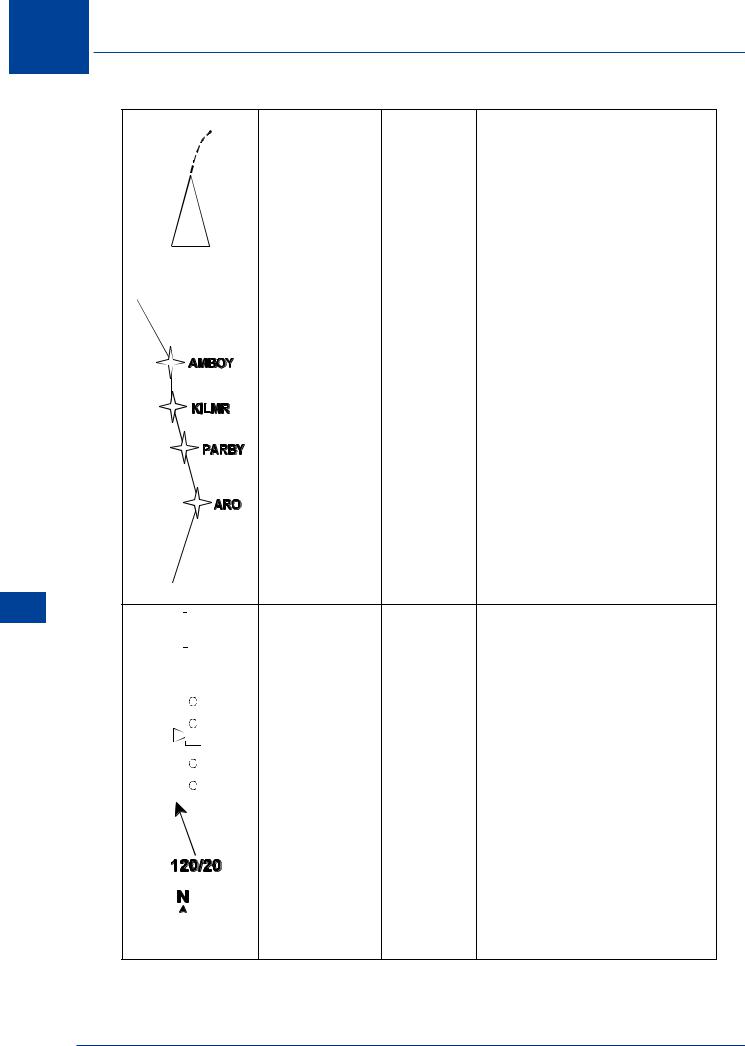
Active Route (M) |
MAP, PLAN |
The active route is displayed with |
|
|
Active Route |
|
continuous lines (M) between |
|
|
Mods (W) |
|
waypoints. Active route |
|
|
Inactive |
|
modi cations are displayed with |
|
|
Route (C) |
|
short dashes (W) between |
|
|
|
|
waypoints. When a change is |
|
|
|
|
activated in the FMC, the short |
|
|
|
|
dashes are replaced by a continuous |
|
|
|
|
|
|
|
|
|
line. Inactive routes are displayed |
|
|
|
|
|
|
|
|
|
with long dashes (C) between |
|
|
|
|
waypoints. |
|
Vertical Pointer |
MAP |
Displays vertical deviation from |
|
(M) and |
|
selected vertical pro le (pointer) in |
|
Deviation Scale |
|
MAP mode during descent only. |
|
(W) |
|
Scale indicates +/- 400 ft deviation. |
|
|
|
|
|
Glide slope |
ILS |
Displays glide slope position and |
|
Pointer (M) and |
|
deviation in ILS mode. |
|
Deviation Scale |
|
|
|
(W) |
|
|
|
|
|
|
|
Wind Speed and |
MAP, |
Indicates wind speed in knots and |
|
Direction (W) |
VOR, ILS |
wind direction with respect to the |
|
|
|
map display orientation and |
|
|
|
compass reference. |
|
|
|
|
|
North Pointer (G) |
PLAN |
Indicates map background is |
|
|
|
orientated and referenced to true |
|
|
|
|
|
|
|
north. |
|
|
|
|
292
Electronic Flight Information System (EFIS) 17
|
|
|
|
|
|
|
|
|
|
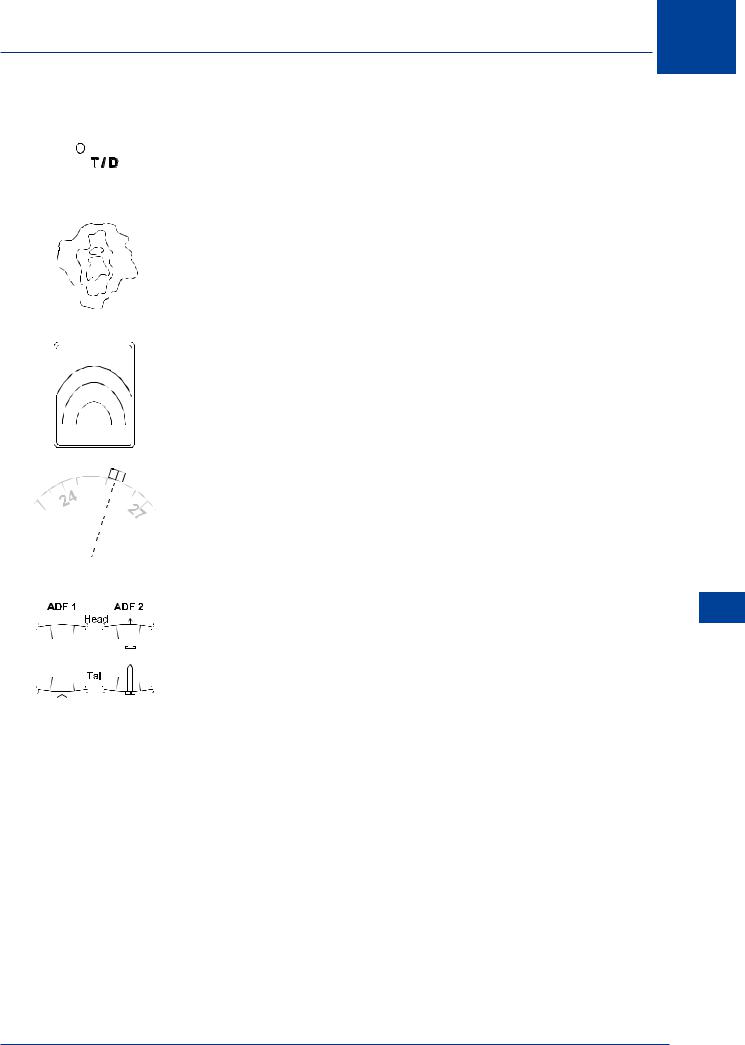
Altitude Pro le |
MAP |
Represents an FMC calculated point |
|
|
|
|
|
|
|
|
|
|
Point and |
|
and is labelled on the ight plan |
|
|
|
|
|
|
|
|
|
|
Identi er(G) |
|
path as” T/C” (top of climb), “T/D” |
|
|
|
|
|
|
|
|
|
|
|
||
|
|
|
|
|
|
|
|
|
|
|
|
(top of descent), “E/D” (end of |
|
|
|
|
|
|
|
|
|
|
|
|
descent) and “S/C” (step climb). |
|
|
|
|
|
|
|
|
|
|
|
|
|
|
|
|
|
|
|
|
|
|
|
Weather Radar |
EXP |
Multicoloured returns are presented |
|
|
|
|
|
|
|
|
|
|
Returns |
VOR/ILS, |
when either “WXR ON” switch is |
|
|
|
|
|
|
|
|
|
|
Mapping Radar |
MAP |
pushed. Most intense regions are |
|
|
|
|
|
|
|
|
|
|
Returns |
|
displayed in Red, lesser Amber |
|
|
|
|
|
|
|
|
|
|
|
lowest intensity Green. Areas of |
|
|
|
|
|
|
|
|
|
|
|
(both G,A,R,M) |
|
|
|
|
|
|
|
|
|
|
|
|
|
turbulence are displayed in magenta |
|
|
|
|
|
|
|
|
|
|
|
|
|
|
|
|
|
|
|
|
|
|
|
|
|
|
|
|
|
|
|
|
|
|
|
|
|
Range Arcs (W) |
EXP VOR, |
Range Arcs are displayed in the |
|
|
|
|
|
|
|
|
|
|
|||
|
|
|
|
|
|
|
|
|
|
|
EXP ILS, |
expanded rose VOR/ILS modes when |
|
|
|
|
|
|
|
|
|
|
|
MAP |
the Weather Radar Switch is ON. |
|
|
|
|
|
|
|
|
|
|
|
Range arcs are displayed in the MAP |
|
|
|
|
|
|
|
|
|
|
|
|
|
|
|
|
|
|
|
|
|
|
|
|
|
|
mode with or without the WXR |
|
|
|
|
|
|
|
|
|
|
|
|
Switch ON. |
|
|
|
|
|
|
|
|
|
|
|
|
|
|
|
|
|
|
|
|
|
|
|
Selected Heading |
ALL |
Indicates the heading selected on |
|
|
|
|
|
|
|
|
|
|
|||
|
|
|
|
|
|
|
|
|
|
Bug (M) |
|
the MCP. A dashed line extends from |
|
|
|
|
|
|
|
|
|
|
|
||
|
|
|
|
|
|
|
|
|
|
|
|
the marker to the aeroplane symbol |
|
|
|
|
|
|
|
|
|
|
and |
|
(except for PLAN mode) for ease in |
|
|
|
|
|
|
|
|
|
|
|
||
|
|
|
|
|
|
|
|
|
|
|
|
tracking the marker when it is out of |
|
|
|
|
|
|
|
|
|
|
Reference Line |
|
view. |
|
|
|
|
|
|
|
|
|
|
|
|
|
|
|
|
|
|
|
|
|
|
|
|
|
|
|
|
|
|
|
|
|
|
|
|
ADF Bearing |
ALL |
Indicates relative bearing to tuned |
|
|
|
|
|
|
|
|
|
|
Pointers |
|
ADF station as received from the |
|
|
|
|
|
|
|
|
|
|
|
||
|
|
|
|
|
|
|
|
|
|
|
|
respective ADF radio. |
|
|
|
|
|
|
|
|
|
|
|
|
|
|
|
|
|
|
|
|
|
|
|
|
|
|
|
|
|
|
|
|
|
|
|
|
|
|
|
|
|
|
|
|
|
|
|
|
|
|
|
|
|
|
|
|
|
|
|
|
|
|
|
|
|
Electronic Flight Information System (EFIS) 17
293
17 Electronic Flight Information System (EFIS)
(EFIS) System Information Flight Electronic 17
|
|
|
|
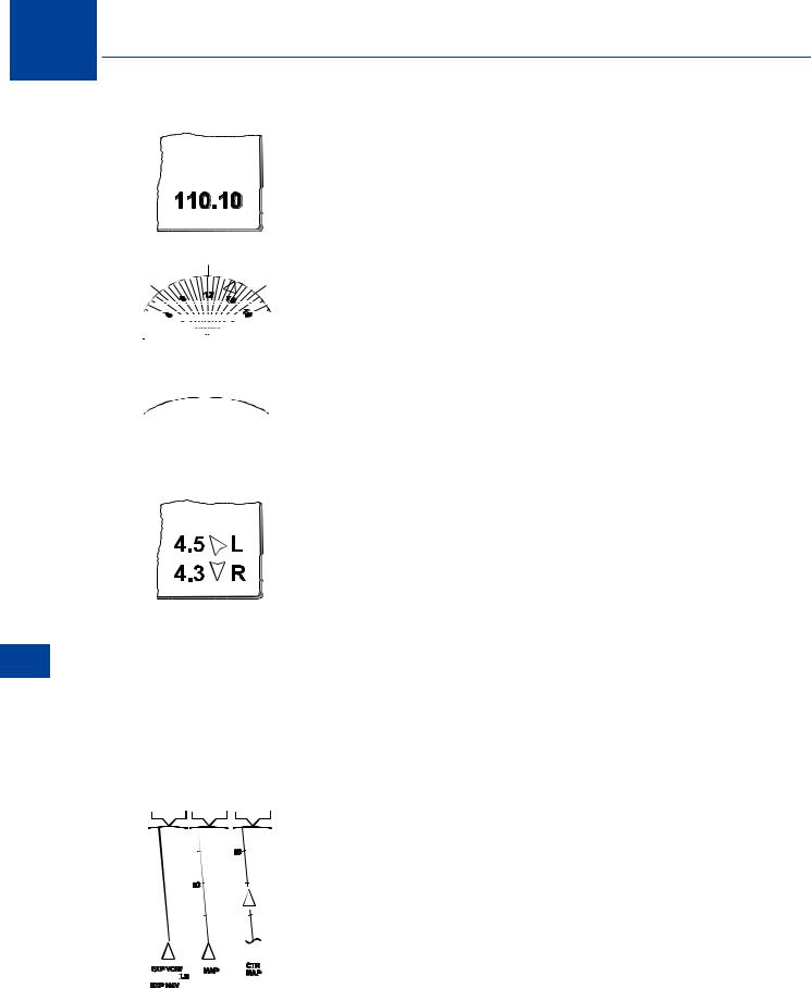
VOR / ILS |
VOR, ILS |
Displays frequency of manually |
|
|
|
|
|
Frequency |
|
tuned navaid. The word ‘AUTO’ is |
|
|
|
|
|
Display (G) |
|
displayed in place of the frequency |
|
|
|
|
|
|
|
if the VHF Nav radio is in the auto |
|
|
|
|
|
|
|
tune |
|
|
|
|
|
|
|
mode |
|
|
|
|
|
|
|
|
|
|
|
|
|
Dri Angle |
FULL |
Indicates aeroplane’s present track. |
|
|
|
|
|
Pointer (W) |
VOR/ILS |
Replaces track line when a Full Rose |
|
|
|
|
|
|
|
mode is selected. |
|
|
|
|
|
|
|
|
|
|
|
|
|
Altitude Range |
MAP |
The intersection of the arc with the |
|
|
|
|
|
Arc (G) |
|
track line is the predicted point |
|
|
|
|
|
|
|
where the MCP altitude will be |
|
|
|
|
|
|
|
reached. The prediction is based on |
|
|
|
|
|
|
|
present ground speed and |
|
|
|
|
|
|
|
aeroplane vertical speed. |
|
|
|
|
|
|
|
|
|
|
|
|
|
Position |
MAP |
NUMBERS - Indicate the Position |
|
|
|
|
|
Di erence |
|
Di erence in NM between the |
|
|
|
|
|
Display (W) |
|
FMC’s present position and the L |
|
|
|
|
|
|
|
IRS and R IRS present positions |
|
|
|
|
|
|
|
respectively. |
|
|
|
|
|
|
|
ARROWS - Rotate through 360° to |
|
|
|
|
|
|
|
indicate the relative bearing to the |
|
|
|
|
|
|
|
associated IRS present position. |
|
|
|
|
|
|
|
L or R - Indicates which IRS present |
|
|
|
|
|
|
|
position the displayed Position |
|
|
|
|
|
|
|
Di erence corresponds to. |
|
|
|
|
|
|
|
Displayed when the Position |
|
|
|
|
|
|
|
Di erence of the L IRS and/or R IRS |
|
|
|
|
|
|
|
exceeds the Position Di erence |
|
|
|
|
|
|
|
limits detected by the FMC or EFIS |
|
|
|
|
|
|
|
Symbol generator. |
|
|
|
|
|
|
|
|
|
|
|
|
|
Present Track |
EXP VOR, |
Displays present ground track based |
|
|
|
|
|
Line (W) and |
EXP ILS, |
on aeroplane heading and wind. |
|
|
|
|
|
Range Scale (W) |
MAP |
Range numeric values are one-half |
|
|
|
|
|
|
|
the actual selected range. With |
|
|
|
|
|
|
|
heading-up orientation, the track |
|
|
|
|
|
|
|
line will be rotated left or right at an |
|
|
|
|
|
|
|
angle equal to the drift angle. |
|
|
|
|
|
|
|
|
|
|
|
|
|
|
|
|
|
|
|
|
|
|
|
|
|
|
|
|
|
|
|
|
|
|
|
|
|
|
|
|
|
|
|
|
|
|
|
|
|
|
|
|
|
|
|
|
|
|
|
|
|
|
|
|
|
294
Electronic Flight Information System (EFIS) 17
|
|
|
|
|
|
|
|
|
Lateral Deviation |
VOR, |
Displays ILS or VOR course deviation |
|
|
|
|
|
|
|
|
|
|
Indicator Bar |
ILS |
|
|
|
|
|
|
|
|
|
|
|
(M) and |
|
ILS 1 dot |
1° Normal Scale |
|
|
|
|
|
|
|
|
|
Deviation Scale |
|
ILS 1 dot |
1/2° Expanded Scale |
|
|
|
|
|
|
|
|
|
(W) |
|
VOR 1 dot |
5° |
|
|
|
|
|
|
|
|
|
|
|
||
|
|
|
|
|
|
|
|
|
|
|
|
|
|
|
|
|
|
|
|
|
|
Selected Course |
EXP ILS, |
Points to selected course as set by |
|
|
|
|
|
|
|
|
|
|
Pointer (W) and |
EXP VOR |
the respective MCP course selector |
|
|
|
|
|
|
|
|
|
|
Line (M) |
|
(VOR/ILS) |
|
|
|
|
|
|
|
|
|
|
|
|
|
|
|
|
|
|
|
|
|
|
|
Selected Course |
FULL VOR, |
Points to selected course as set by |
|
|
|
|
|
|
|
|
|
|
Pointer (W) |
FULL ILS |
the respective MCP course selector |
|
|
|
|
|
|
|
|
|
|
|
|
(VOR/ILS) |
|
|
|
|
|
|
|
|
|
|
To / From |
|
TO/FROM symbol is displayed when |
|
|
|
|
|
|
|
|
|
|
Pointer (W) |
|
VOR navigation is being used. |
|
|
|
|
|
|
|
|
|
|
|
|
|
|
|
|
|
|
|
|
|
|
|
To/From |
VOR |
Operative in VOR Mode only. |
|
|
|
|
|
|
|
|||||||
|
|
|
|
|
|
|
|
|
Annunciation |
|
Indicates whether or not the |
|
|
|
|
|
|
|
|
||||||
|
|
|
|
|
|
|
||||||
|
|
|
|
|
|
|
|
|
(W) |
|
selected course, if intercepted |
|
|
|
|
|
|
|
|
||||||
|
|
|
|
|
|
|
|
|
|
|
directly, and tracked, would take |
|
|
|
|
|
|
|
|
|
|
|
|
||
|
|
|
|
|
|
|
|
|
|
|
the aircra TO or FROM the |
|
|
|
|
|
|
|
|
|
|
|
|
station. |
|
|
|
|
|
|
|
|
|
|
|
|
|
|
|
|
|
|
|
|
|
|
|
O -route |
MAP, PLAN |
When the WPT switch is ON, FMC |
|
|
|
|
|
|
|
|
|
|
Waypoint (C) |
|
database waypoints not used in |
|
|
|
|
|
|
|
|
|
|
|
|
the selected ight plan route are |
|
|
|
|
|
|
|
|
|
|
|
|
||
|
|
|
|
|
|
|
|
|
|
|
displayed. Displayed only for HSI |
|
|
|
|
|
|
|
|
|
|
|
|
ranges of 10, 20, or 40 NM. |
|
|
|
Airport (C) |
MAP, PLAN |
ARPT switch - OFF |
|
|
|
|
Only origin and destination are |
|
|
|
|
displayed. |
|
|
|
|
ARPT switch - ON |
|
|
|
|
All FMC database airports within |
|
|
|
|
the MAP area are displayed. |
|
|
|
|
|
|
|
Airport Identi er |
MAP, PLAN |
Available when the EHSI display |
|
|
and Runway (W) |
|
range is 80, 160, or 320 NM. |
|
|
|
|
Displayed if the airport has been |
|
|
|
|
selected as the origin or destination |
|
|
|
|
|
|
|
|
|
airport with a speci c runway |
|
|
|
|
selected. |
Electronic Flight Information System (EFIS) 17
295
17 Electronic Flight Information System (EFIS)
(EFIS) System Information Flight Electronic 17
|
|
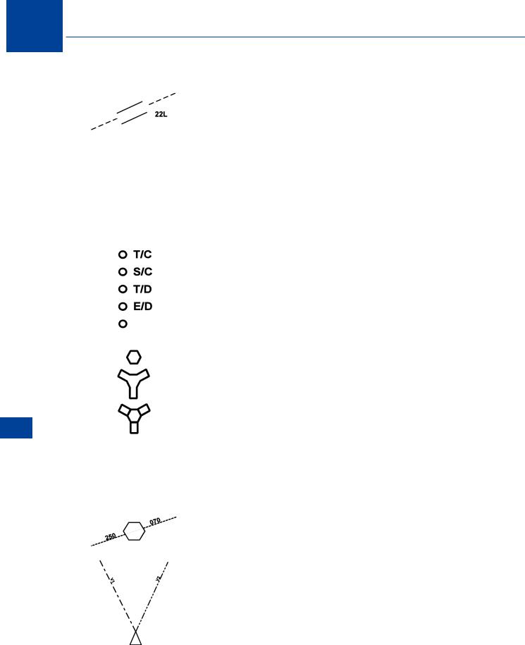
Airport and |
MAP, PLAN |
Available when the EHSI display |
|
|
|
Runway (W) |
|
range is 10, 20, or 40 NM. |
|
|
|
|
|
Displayed if the airport has been |
|
|
|
|
|
selected as the origin or |
|
|
|
|
|
destination airport with a speci c |
|
|
|
|
|
runway selected. |
|
|
|
|
|
Runway symbol is scaled to |
|
|
|
|
|
represent the length of the |
|
|
|
|
|
selected runway. |
|
|
|
|
|
The dashed centre lines extend |
|
|
|
|
|
outward 14.2 NM from the |
|
|
|
|
|
runway thresholds. |
|
|
|
|
|
|
|
|
|
Vertical Pro le |
MAP, PLAN |
Represents an FMC computed |
|
|
|
Points (G) |
|
vertical pro le point in the active |
|
|
|
|
|
ight plan as T/C (top-of-climb), T/D |
|
|
|
Identi ers (G) |
|
(top-of-descent), S/C (step-climb), |
|
|
|
|
|
and E/D (end-of-descent). |
|
|
|
|
|
A deceleration segment point has |
|
|
|
|
|
no identi er. |
|
|
|
|
|
|
|
|
|
VOR (C, G) |
MAP, PLAN |
NAV AID switch - OFF |
|
|
|
|
|
Tuned Navaids (excluding NDBs) are |
|
|
|
DME/TACAN |
|
displayed in green. |
|
|
|
(C, G) |
|
NAV AID switch - ON |
|
|
|
|
|
All appropriate navaids in the FMC |
|
|
|
VORTAC (C, G) |
|
database and within the MAP area |
|
|
|
|
|
are displayed when the range is 10, |
|
|
|
|
|
20, or 40 NM. Only high altitude |
|
|
|
|
|
navaids are displayed when selected |
|
|
|
|
|
range is 80, 160, or 320 NM. |
|
|
|
|
|
Nav aids not being used are |
|
|
|
|
|
displayed in Cyan (blue) |
|
|
|
|
|
|
|
|
|
Manually Tuned |
MAP, PLAN |
When a VOR navaid is manually |
|
|
|
VOR Radials (G) |
|
tuned, the associated MCP selected |
|
|
|
|
|
course and its reciprocal are |
|
|
|
|
|
displayed. |
|
|
|
|
|
|
|
|
|
VOR Radials (G) |
MAP |
The VOR/ADF switch on the EFIS |
|
|
|
|
|
control panel must be ON and a |
|
|
|
|
|
valid VOR signal must be received. |
|
|
|
|
|
|
|
|
|
|
|
|
|
296
Electronic Flight Information System (EFIS) 17
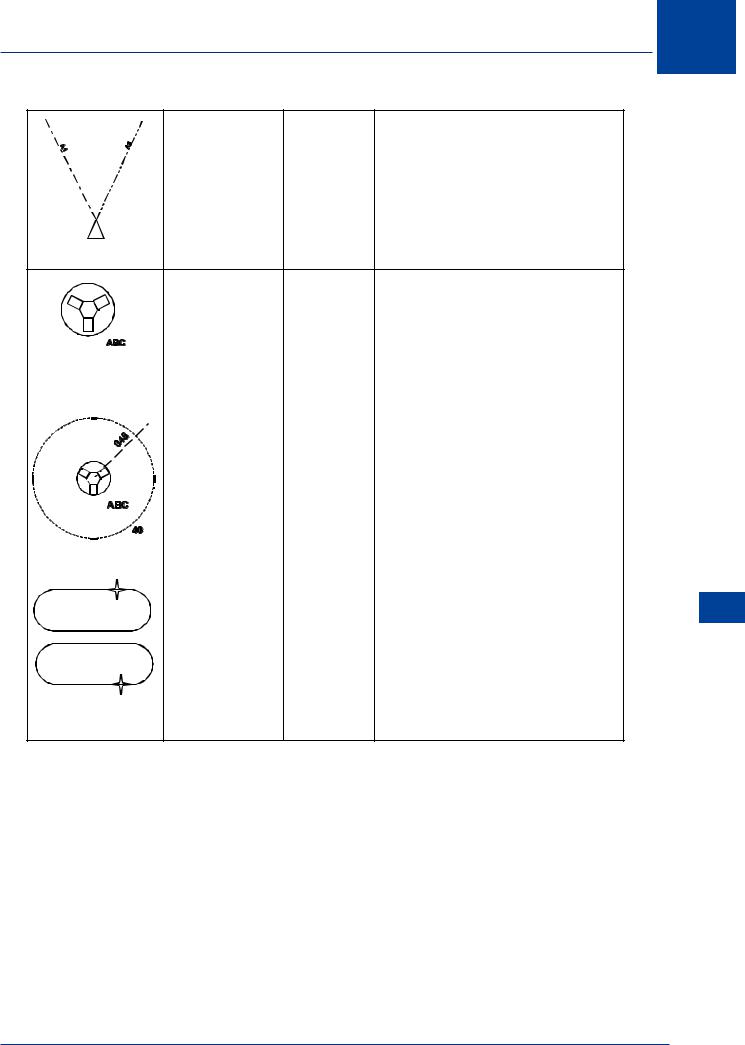
ADF Bearings |
MAP |
The VOR/ADF switch on the EFIS |
(G) |
|
control panel must be ON and a valid |
|
|
ADF signal must be received. |
|
|
Displays relative bearing to the tuned |
|
|
ADF station(s). |
Selected Fix |
MAP, PLAN |
Depicts the selected reference point |
Circle (G) Fix |
|
as entered on the FMC/CDU FIX INFO |
Symbol and |
|
page. Can appear with other special |
Identi er (C or |
|
map symbols (e.g. VOR, VORTAC, |
G) |
|
airport or waypoint etc.) if stored in |
|
|
the FMC data base. |
|
|
|
Selected Fix |
MAP, PLAN |
A x reference radial is displayed for |
Radial (G) |
|
each downtrack bearing entered on |
|
|
the FMC / CDU FIX INFO page. |
Selected Fix |
|
|
Circle (G) |
|
A DME reference circle is displaye |
|
|
for each distance entered on the |
|
|
FMC /d CDU FIX INFO page. |
|
|
|
Holding Pattern |
MAP, PLAN |
Appears as a xed size holding |
|
|
pattern if selected range is greater |
Active (M) |
|
than 80 NM. |
Modi cation (W) |
|
A scaled representation of the |
Inactive (C) |
|
|
|
|
holding pattern is displayed when |
|
|
the selected range is 80 NM or less |
|
|
and the aeroplane is within 3 min. of |
|
|
the holding x. |
Electronic Flight Information System (EFIS) 17
297

17 Electronic Flight Information System (EFIS)
(EFIS) System Information Flight Electronic 17
298