

- •Textbook Series
- •Contents
- •1 Properties of Radio Waves
- •Introduction
- •The Radio Navigation Syllabus
- •Electromagnetic (EM) Radiation
- •Polarization
- •Radio Waves
- •Wavelength
- •Frequency Bands
- •Phase Comparison
- •Practice Frequency (
- •Answers to Practice Frequency (
- •Questions
- •Answers
- •2 Radio Propagation Theory
- •Introduction
- •Factors Affecting Propagation
- •Propagation Paths
- •Non-ionospheric Propagation
- •Ionospheric Propagation
- •Sky Wave
- •HF Communications
- •Propagation Summary
- •Super-refraction
- •Sub-refraction
- •Questions
- •Answers
- •3 Modulation
- •Introduction
- •Keyed Modulation
- •Amplitude Modulation (AM)
- •Single Sideband (SSB)
- •Frequency Modulation (FM)
- •Phase Modulation
- •Pulse Modulation
- •Emission Designators
- •Questions
- •Answers
- •4 Antennae
- •Introduction
- •Basic Principles
- •Aerial Feeders
- •Polar Diagrams
- •Directivity
- •Radar Aerials
- •Modern Radar Antennae
- •Questions
- •Answers
- •5 Doppler Radar Systems
- •Introduction
- •The Doppler Principle
- •Airborne Doppler
- •Janus Array System
- •Doppler Operation
- •Doppler Navigation Systems
- •Questions
- •Answers
- •6 VHF Direction Finder (VDF)
- •Introduction
- •Procedures
- •Principle of Operation
- •Range of VDF
- •Factors Affecting Accuracy
- •Determination of Position
- •VDF Summary
- •Questions
- •Answers
- •7 Automatic Direction Finder (ADF)
- •Introduction
- •Non-directional Beacon (NDB)
- •Principle of Operation
- •Frequencies and Types of NDB
- •Aircraft Equipment
- •Emission Characteristics and Beat Frequency Oscillator (BFO)
- •Presentation of Information
- •Uses of the Non-directional Beacon
- •Plotting ADF Bearings
- •Track Maintenance Using the RBI
- •Homing
- •Tracking Inbound
- •Tracking Outbound
- •Drift Assessment and Regaining Inbound Track
- •Drift Assessment and Outbound Track Maintenance
- •Holding
- •Runway Instrument Approach Procedures
- •Factors Affecting ADF Accuracy
- •Factors Affecting ADF Range
- •Accuracy
- •ADF Summary
- •Questions
- •Answers
- •8 VHF Omni-directional Range (VOR)
- •Introduction
- •The Principle of Operation
- •Terminology
- •Transmission Details
- •Identification
- •Monitoring
- •Types of VOR
- •The Factors Affecting Operational Range of VOR
- •Factors Affecting VOR Beacon Accuracy
- •The Cone of Ambiguity
- •Doppler VOR (DVOR)
- •VOR Airborne Equipment
- •VOR Deviation Indicator
- •Radio Magnetic Indicator (RMI)
- •Questions
- •In-flight Procedures
- •VOR Summary
- •Questions
- •Annex A
- •Annex B
- •Annex C
- •Answers
- •Answers to Page 128
- •9 Instrument Landing System (ILS)
- •Introduction
- •ILS Components
- •ILS Frequencies
- •DME Paired with ILS Channels
- •ILS Identification
- •Marker Beacons
- •Ground Monitoring of ILS Transmissions
- •ILS Coverage
- •ILS Principle of Operation
- •ILS Presentation and Interpretation
- •ILS Categories (ICAO)
- •Errors and Accuracy
- •Factors Affecting Range and Accuracy
- •ILS Approach Chart
- •ILS Calculations
- •ILS Summary
- •Questions
- •Answers
- •10 Microwave Landing System (MLS)
- •Introduction
- •ILS Disadvantages
- •The MLS System
- •Principle of Operation
- •Airborne Equipment
- •Question
- •Answer
- •11 Radar Principles
- •Introduction
- •Types of Pulsed Radars
- •Radar Applications
- •Radar Frequencies
- •Pulse Technique
- •Theoretical Maximum Range
- •Primary Radars
- •The Range of Primary Radar
- •Radar Measurements
- •Radar Resolution
- •Moving Target Indication (MTI)
- •Radar Antennae
- •Questions
- •Answers
- •12 Ground Radar
- •Introduction
- •Area Surveillance Radars (ASR)
- •Terminal Surveillance Area Radars
- •Aerodrome Surveillance Approach Radars
- •Airport Surface Movement Radar (ASMR)
- •Questions
- •Answers
- •13 Airborne Weather Radar
- •Introduction
- •Component Parts
- •AWR Functions
- •Principle of Operation
- •Weather Depiction
- •Control Unit
- •Function Switch
- •Mapping Operation
- •Pre-flight Checks
- •Weather Operation
- •Colour AWR Controls
- •AWR Summary
- •Questions
- •Answers
- •14 Secondary Surveillance Radar (SSR)
- •Introduction
- •Advantages of SSR
- •SSR Display
- •SSR Frequencies and Transmissions
- •Modes
- •Mode C
- •SSR Operating Procedure
- •Special Codes
- •Disadvantages of SSR
- •Mode S
- •Pulses
- •Benefits of Mode S
- •Communication Protocols
- •Levels of Mode S Transponders
- •Downlink Aircraft Parameters (DAPS)
- •Future Expansion of Mode S Surveillance Services
- •SSR Summary
- •Questions
- •Answers
- •15 Distance Measuring Equipment (DME)
- •Introduction
- •Frequencies
- •Uses of DME
- •Principle of Operation
- •Twin Pulses
- •Range Search
- •Beacon Saturation
- •Station Identification
- •VOR/DME Frequency Pairing
- •DME Range Measurement for ILS
- •Range and Coverage
- •Accuracy
- •DME Summary
- •Questions
- •Answers
- •16 Area Navigation Systems (RNAV)
- •Introduction
- •Benefits of RNAV
- •Types and Levels of RNAV
- •A Simple 2D RNAV System
- •Operation of a Simple 2D RNAV System
- •Principle of Operation of a Simple 2D RNAV System
- •Limitations and Accuracy of Simple RNAV Systems
- •Level 4 RNAV Systems
- •Requirements for a 4D RNAV System
- •Control and Display Unit (CDU)
- •Climb
- •Cruise
- •Descent
- •Kalman Filtering
- •Questions
- •Appendix A
- •Answers
- •17 Electronic Flight Information System (EFIS)
- •Introduction
- •EHSI Controller
- •Full Rose VOR Mode
- •Expanded ILS Mode
- •Full Rose ILS Mode
- •Map Mode
- •Plan Mode
- •EHSI Colour Coding
- •EHSI Symbology
- •Questions
- •Appendix A
- •Answers
- •18 Global Navigation Satellite System (GNSS)
- •Introduction
- •Satellite Orbits
- •Position Reference System
- •The GPS Segments
- •The Space Segment
- •The Control Segment
- •The User Segment
- •Principle Of Operation
- •GPS Errors
- •System Accuracy
- •Integrity Monitoring
- •Differential GPS (DGPS)
- •Combined GPS and GLONASS Systems
- •Questions
- •Answers
- •19 Revision Questions
- •Questions
- •Answers
- •Specimen Examination Paper
- •Appendix A
- •Answers to Specimen Examination Paper
- •Explanation of Selected Questions
- •20 Index
Area Navigation Systems (RNAV) 16
Operation of a Simple 2D RNAV System
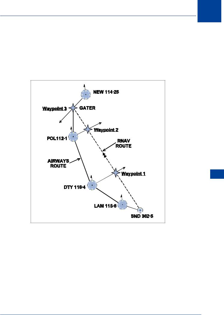
A simple RNAV system uses rho/theta (range/bearing) to define position, which is derived from range and bearing information from VOR/DME stations. The pilot defines waypoints along the route to be flown as range and bearing from suitably located VOR/DME. Then the equipment, using the VOR/DME bearing and range, computes the QDM and distance to the waypoint and presents the information to the pilot on a CDI or HSI as if the waypoint itself is a VOR/DME station, hence these waypoints are known as phantom stations.
|
NM |
NM |
|
218R/26 |
066R/29 |
||
|
|||
|
|
||
|
|
NM |
|
|
|
067R/42 |
|
|
|
16 |
|
|
|
Area Navigation Systems (RNAV) |
Figure 16.2 An RNAV route & waypoints
In the diagram the pilot has defined waypoints along the planned route from SND to NEW using available and sensibly placed VOR/DME.
Waypoints may be selected and programmed for:
•En route navigation.
•Initial approach fixes.
•Locator Outer Markers.
•ILS frequencies (when selected the instrumentation automatically reverts to ILS mode). The following table shows the inputs that would be required for the above RNAV route.
263
16 Area Navigation Systems (RNAV)
WAYPOINT |
STATION |
FREQUENCY |
RADIAL |
DISTANCE |
APPLICATION |
|
|
|
|
|
|
1 |
DTY |
116.4 MHz |
067 |
42 |
En route Nav. |
|
|
|
|
|
|
2 |
POL |
112.1 MHz |
066 |
29 |
En route Nav. |
|
|
|
|
|
|
3 |
NEW |
114.25 MHz |
218 |
26 |
En route Nav. |
|
|
|
|
|
|
4 |
NEW |
114.25 MHz |
251 |
4 |
Holding LOM |
|
|
|
|
|
|
5 |
I-NC |
111.5 MHz |
N/A |
N/A |
ILS |
|
|
|
|
|
|
Principle of Operation of a Simple 2D RNAV System
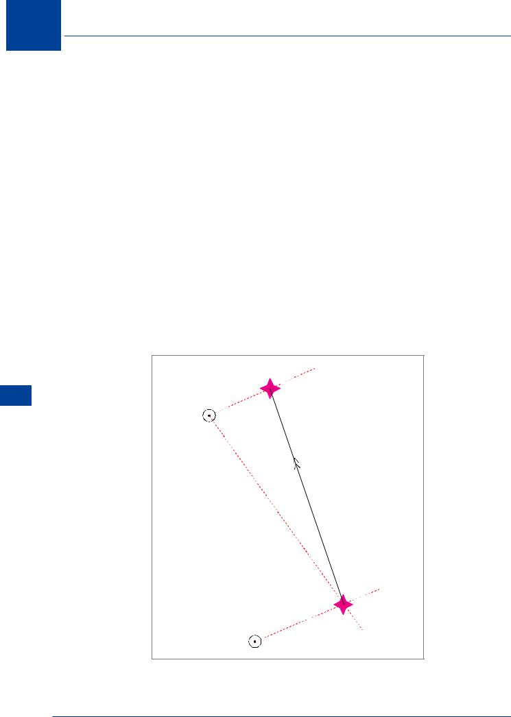
Refer to Figure 16.3. The aircraft is flying from waypoint 1 (WP1) defined by DTY VOR/DME to waypoint 2 (WP2) defined by POL VOR/DME. As the aircraft arrives at WP1, POL is selected and the range and bearing measured (145(M)/104 NM). The RNAV knows its position with respect to POL and the pilot has already input waypoint 2 with respect to POL. The computer can now compute the track and distance from WP1 to WP2 (340(M)/102 NM) since it has two sides, the included angle and the orientation of magnetic north. The RNAV now continually computes the aircraft position with respect to POL and compares this position with the computed track to determine the cross-track error and the distance to go. Steering demands are fed to a CDI or HSI for the pilot to keep the aircraft on track and give continuous range read-out to WP2. It should be noted that on such a system the indications of deviation from track are in NM.
(RNAV) Systems Navigation Area 16
 066/29
POL |
WAYPOINT 2 |
|
145/104
067/42
WAYPOINT 1
DTY
Figure 16.3
264
Area Navigation Systems (RNAV) 16
Limitations and Accuracy of Simple RNAV Systems
The beacons are selected by the pilot during the pre-flight planning and the pilot must ensure that each waypoint is within DOC of the VOR/DME designating that waypoint and of the VOR/ DME designating the next waypoint.
Slant range error in DME must be considered in selecting facilities close to track.
The pilot must ensure that the information is correctly input into the CDU because the computer cannot recognize or rectify mistakes.
To avoid positional errors the aircraft must at all times be within the DOC of the in use facility. The accuracy of the fixing information is dependent on range and whether the VOR or DME element is predominant. If the VOR/DME is close to the planned track to/from the waypoint, the along track element will be most accurate. If the VOR/DME designating the way point is perpendicular to the track, the across track will be most accurate.
Area Navigation Systems (RNAV) 16
265
16 Area Navigation Systems (RNAV)
Level 4 RNAV Systems
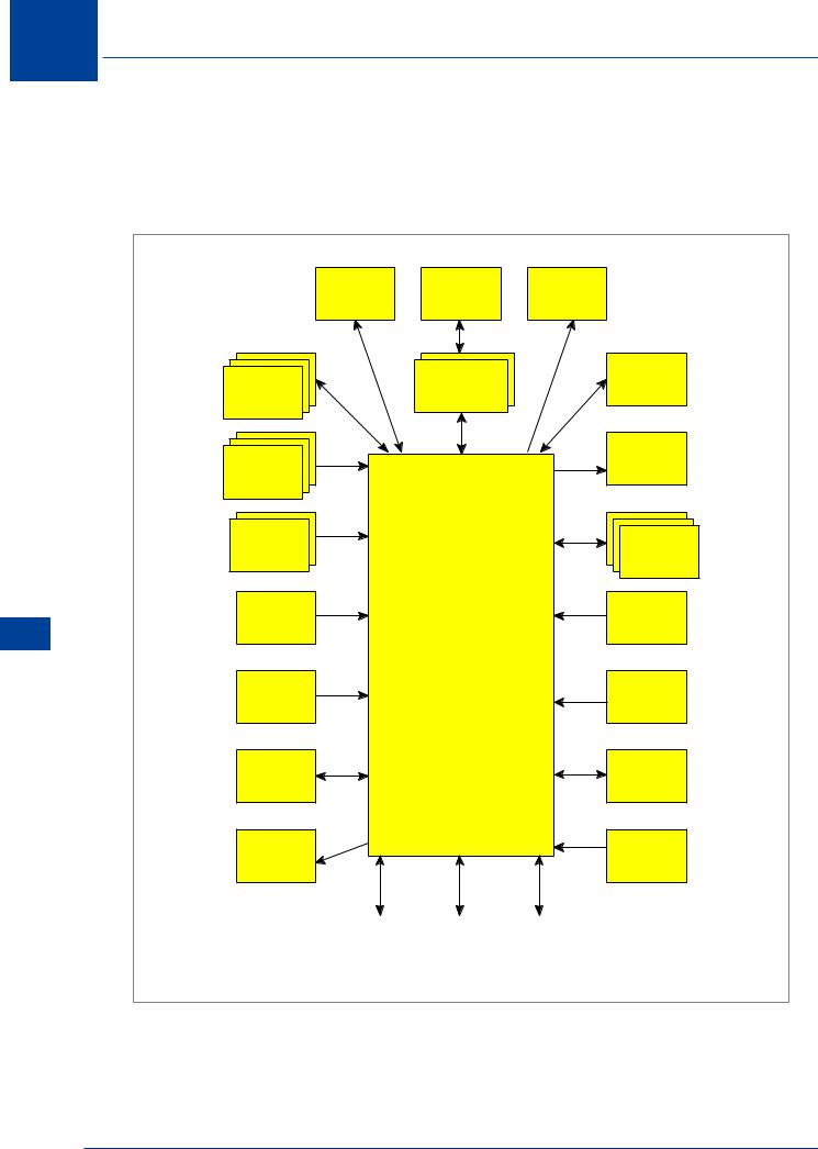
The area navigation function in modern passenger aircraft is carried out by a flight management computer (FMC) which also provides guidance and performance functions. The system outlined below is specific to the BOEING 737-800, but the principle is true for all aircraft.
(RNAV) Systems Navigation Area 16
ELECTRONIC INTERFACE UNIT
FLIGHT
CONTROL
COMPUTER
AIR
DATA
COMPUTER
FUEL
QUANTITY INDICATING SYSTEM
WEIGHT
AND
BALANCE
COMPUTER
OFFSIDE
FMC
ADF
AUTO |
|
INTEGRATED |
THROTTLE |
PILOT |
DISPLAY |
SERVO |
|
SYSTEM |
|
|
(ND & PFD) |
|
|
CENTRAL |
|
MCDU |
MAINTENANCE |
|
|
COMPUTER |
|
|
ELECTRONIC |
|
|
ENGINE |
|
|
CONTROL |
INERTIAL
REFERENCE
SYSTEM
DIGITAL
CLOCK
FMC
AUTOPILOT
FLIGHT
DIRECTOR
SYSTEM
MODE
CONTROL
PANEL
DATABASE
LOADER
DME |
|
VOR |
|
ILS / MLS |
|
|
|
|
|
Figure 16.4 FMS schematic
266