

- •Textbook Series
- •Contents
- •1 Properties of Radio Waves
- •Introduction
- •The Radio Navigation Syllabus
- •Electromagnetic (EM) Radiation
- •Polarization
- •Radio Waves
- •Wavelength
- •Frequency Bands
- •Phase Comparison
- •Practice Frequency (
- •Answers to Practice Frequency (
- •Questions
- •Answers
- •2 Radio Propagation Theory
- •Introduction
- •Factors Affecting Propagation
- •Propagation Paths
- •Non-ionospheric Propagation
- •Ionospheric Propagation
- •Sky Wave
- •HF Communications
- •Propagation Summary
- •Super-refraction
- •Sub-refraction
- •Questions
- •Answers
- •3 Modulation
- •Introduction
- •Keyed Modulation
- •Amplitude Modulation (AM)
- •Single Sideband (SSB)
- •Frequency Modulation (FM)
- •Phase Modulation
- •Pulse Modulation
- •Emission Designators
- •Questions
- •Answers
- •4 Antennae
- •Introduction
- •Basic Principles
- •Aerial Feeders
- •Polar Diagrams
- •Directivity
- •Radar Aerials
- •Modern Radar Antennae
- •Questions
- •Answers
- •5 Doppler Radar Systems
- •Introduction
- •The Doppler Principle
- •Airborne Doppler
- •Janus Array System
- •Doppler Operation
- •Doppler Navigation Systems
- •Questions
- •Answers
- •6 VHF Direction Finder (VDF)
- •Introduction
- •Procedures
- •Principle of Operation
- •Range of VDF
- •Factors Affecting Accuracy
- •Determination of Position
- •VDF Summary
- •Questions
- •Answers
- •7 Automatic Direction Finder (ADF)
- •Introduction
- •Non-directional Beacon (NDB)
- •Principle of Operation
- •Frequencies and Types of NDB
- •Aircraft Equipment
- •Emission Characteristics and Beat Frequency Oscillator (BFO)
- •Presentation of Information
- •Uses of the Non-directional Beacon
- •Plotting ADF Bearings
- •Track Maintenance Using the RBI
- •Homing
- •Tracking Inbound
- •Tracking Outbound
- •Drift Assessment and Regaining Inbound Track
- •Drift Assessment and Outbound Track Maintenance
- •Holding
- •Runway Instrument Approach Procedures
- •Factors Affecting ADF Accuracy
- •Factors Affecting ADF Range
- •Accuracy
- •ADF Summary
- •Questions
- •Answers
- •8 VHF Omni-directional Range (VOR)
- •Introduction
- •The Principle of Operation
- •Terminology
- •Transmission Details
- •Identification
- •Monitoring
- •Types of VOR
- •The Factors Affecting Operational Range of VOR
- •Factors Affecting VOR Beacon Accuracy
- •The Cone of Ambiguity
- •Doppler VOR (DVOR)
- •VOR Airborne Equipment
- •VOR Deviation Indicator
- •Radio Magnetic Indicator (RMI)
- •Questions
- •In-flight Procedures
- •VOR Summary
- •Questions
- •Annex A
- •Annex B
- •Annex C
- •Answers
- •Answers to Page 128
- •9 Instrument Landing System (ILS)
- •Introduction
- •ILS Components
- •ILS Frequencies
- •DME Paired with ILS Channels
- •ILS Identification
- •Marker Beacons
- •Ground Monitoring of ILS Transmissions
- •ILS Coverage
- •ILS Principle of Operation
- •ILS Presentation and Interpretation
- •ILS Categories (ICAO)
- •Errors and Accuracy
- •Factors Affecting Range and Accuracy
- •ILS Approach Chart
- •ILS Calculations
- •ILS Summary
- •Questions
- •Answers
- •10 Microwave Landing System (MLS)
- •Introduction
- •ILS Disadvantages
- •The MLS System
- •Principle of Operation
- •Airborne Equipment
- •Question
- •Answer
- •11 Radar Principles
- •Introduction
- •Types of Pulsed Radars
- •Radar Applications
- •Radar Frequencies
- •Pulse Technique
- •Theoretical Maximum Range
- •Primary Radars
- •The Range of Primary Radar
- •Radar Measurements
- •Radar Resolution
- •Moving Target Indication (MTI)
- •Radar Antennae
- •Questions
- •Answers
- •12 Ground Radar
- •Introduction
- •Area Surveillance Radars (ASR)
- •Terminal Surveillance Area Radars
- •Aerodrome Surveillance Approach Radars
- •Airport Surface Movement Radar (ASMR)
- •Questions
- •Answers
- •13 Airborne Weather Radar
- •Introduction
- •Component Parts
- •AWR Functions
- •Principle of Operation
- •Weather Depiction
- •Control Unit
- •Function Switch
- •Mapping Operation
- •Pre-flight Checks
- •Weather Operation
- •Colour AWR Controls
- •AWR Summary
- •Questions
- •Answers
- •14 Secondary Surveillance Radar (SSR)
- •Introduction
- •Advantages of SSR
- •SSR Display
- •SSR Frequencies and Transmissions
- •Modes
- •Mode C
- •SSR Operating Procedure
- •Special Codes
- •Disadvantages of SSR
- •Mode S
- •Pulses
- •Benefits of Mode S
- •Communication Protocols
- •Levels of Mode S Transponders
- •Downlink Aircraft Parameters (DAPS)
- •Future Expansion of Mode S Surveillance Services
- •SSR Summary
- •Questions
- •Answers
- •15 Distance Measuring Equipment (DME)
- •Introduction
- •Frequencies
- •Uses of DME
- •Principle of Operation
- •Twin Pulses
- •Range Search
- •Beacon Saturation
- •Station Identification
- •VOR/DME Frequency Pairing
- •DME Range Measurement for ILS
- •Range and Coverage
- •Accuracy
- •DME Summary
- •Questions
- •Answers
- •16 Area Navigation Systems (RNAV)
- •Introduction
- •Benefits of RNAV
- •Types and Levels of RNAV
- •A Simple 2D RNAV System
- •Operation of a Simple 2D RNAV System
- •Principle of Operation of a Simple 2D RNAV System
- •Limitations and Accuracy of Simple RNAV Systems
- •Level 4 RNAV Systems
- •Requirements for a 4D RNAV System
- •Control and Display Unit (CDU)
- •Climb
- •Cruise
- •Descent
- •Kalman Filtering
- •Questions
- •Appendix A
- •Answers
- •17 Electronic Flight Information System (EFIS)
- •Introduction
- •EHSI Controller
- •Full Rose VOR Mode
- •Expanded ILS Mode
- •Full Rose ILS Mode
- •Map Mode
- •Plan Mode
- •EHSI Colour Coding
- •EHSI Symbology
- •Questions
- •Appendix A
- •Answers
- •18 Global Navigation Satellite System (GNSS)
- •Introduction
- •Satellite Orbits
- •Position Reference System
- •The GPS Segments
- •The Space Segment
- •The Control Segment
- •The User Segment
- •Principle Of Operation
- •GPS Errors
- •System Accuracy
- •Integrity Monitoring
- •Differential GPS (DGPS)
- •Combined GPS and GLONASS Systems
- •Questions
- •Answers
- •19 Revision Questions
- •Questions
- •Answers
- •Specimen Examination Paper
- •Appendix A
- •Answers to Specimen Examination Paper
- •Explanation of Selected Questions
- •20 Index

15
(DME) Equipment Measuring Distance 15
Distance Measuring Equipment (DME)
Frequencies
Channels
DME (emission code P0N) is a secondary radar system operating between 960 and 1215 MHz in the UHF band at 1 MHz spacing; this provides 252 spot frequencies or channels.
There is always a difference of +/- 63 MHz between the interrogation and transponding frequencies. The channels are numbered 1 to 126X and 1 to 126Y. A channel number is selected by the pilot of a TACAN (TACtical Air Navigation) equipped military aircraft; this equipment provides the pilot with range and bearing. Civil aircraft have the cheaper VOR/DME equipment and select the appropriate paired VHF frequency to obtain range from either a DME or military TACAN facility.
Example Channel Numbers and Paired Frequencies
BEACON |
Aircraft |
Beacon |
Military |
Civil |
|
Interrogation |
Transponds |
Aircraft Select |
Aircraft Select |
||
|
|||||
MAZ Tacan |
1131 MHz |
1194 MHz |
Channel 107X |
116.0 MHz |
|
|
|
|
|
|
|
OX DME |
1148 MHz |
1211 MHz |
Channel 124X |
117.7 MHz |
|
|
|
|
|
|
DME PairedWith ILS LocalizerTransmitter
DME is also frequency paired with the ILS localizer frequencies. These DME supplement or replace the range information provided by the Marker Beacons. The range information is zero referenced to the ILS runway threshold. DME is obtained by selecting the ILS frequency.
Uses of DME
A DME:
•provides very accurate slant range, a circular position line and in conjunction with another DME, or a co-sited VOR, two position line fixes.
•integrates the change of slant range into groundspeed and elapsed times when the aircraft is fitted with an appropriate computer.
•permits more accurate flying of holding patterns and DME arcs.
•provides range and height checks when flying non-precision approach procedures, e.g. locator only and VOR let-downs.
•indicates accurate ranges to the runway threshold, and heights for range, when flying an ILS/DME procedure.
•facilitates radar identification when the pilot reports his VOR/DME position.
•facilitates the separation and control of aircraft in non-radar airspace, based upon a VOR/ DME fix reported by individual aircraft.
•is the basis for a simple Area Navigation (RNAV) system when the appropriate computerization is fitted.
•provides accurate range inputs into the more complex and accurate RNAV systems; twin, self-selecting DME/DME are used.
246
Distance Measuring Equipment (DME) 15
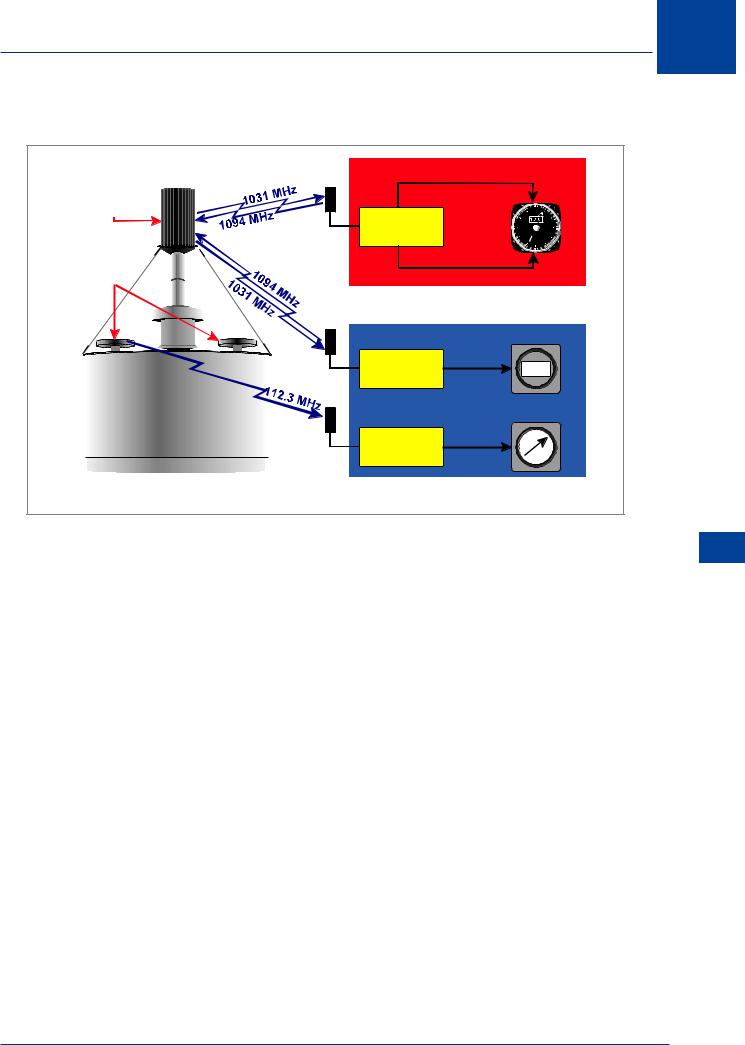
Principle of Operation
TACAN |
|
DISTANCE |
|
ANTENNA |
|
SELECT |
|
|
TACAN |
|
|
|
CHANNEL |
|
|
|
|
70X |
|
VOR |
|
|
|
ANTENNAE |
|
BEARING |
|
|
DME |
DISTANCE |
235 |
|
|
||
|
VOR |
BEARING |
|
|
|
|
|
VORTAC GROUND STATION |
AIRBORNE EQUIPMENT |
||
Figure 15.6 VORTAC
PulseTechnique
DME is a secondary radar system providing slant range by pulse technique.
The aircraft’s interrogator transmits a stream of omni-directional pulses on the carrier frequency of the ground transponder. Simultaneously the interrogator’s receiver starts a Range Search. At the transponder on the ground the received interrogation pulses are re-transmitted, after a delay of 50 µs, at a frequency that is +/- 63 MHz removed from the interrogation frequency.
The airborne system identifies its own unique stream of pulses and measures the time interval, electronically, between the start of the interrogation and the reception of the response from the transponder. The time measurement, and hence range, is very accurate and is based upon the speed of radio waves i.e. 3 × 10⁸ m/s. A modern DME is inherently accurate to +/- 0.2 NM
In theory up to 100 aircraft can interrogate a DME transponder. Thus each aircraft is receiving its own returning paired pulses plus those which result from other aircrafts’ interrogations, as the pulses have the same carrier frequency.
The width of the interrogation pulses is 3.5 µs (1050 m) and they are transmitted in pairs; (the interval between the individual pulses of a pair is 12 µs for X channel and 36 µs for Y channel).
Distance Measuring Equipment (DME) 15
247
15 Distance Measuring Equipment (DME)
Aircraft Range Determination
(DME) Equipment Measuring Distance 15
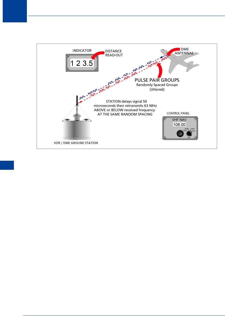
Figure 15.7 The Principle of Range Measurement
For an individual aircraft to achieve an unambiguous slant range measurement and overcome the problem of identification:
•Each aircraft’s interrogator is programmed to transmit its paired pulses at random intervals i.e. the transmission sequence of pulses is irregular or jittered. This differentiates its pulses from all the others.
•At the instant of transmission, the receiver of an interrogator sets up gates to match the random PRF of the transmitted twin pulses.
•The responses on the transponder’s carrier frequency include an individual aircraft’s paired pulses plus those from other aircraft.
•The receiving equipment of an aircraft is designed so that only the responses which match its randomized PRF are allowed through the gates. The pulses have now achieved lock-on i.e. the DME enters the tracking mode.
•As the aircraft’s range from the station increases or decreases (unless the aircraft is circling) the gates move to accommodate the corresponding increase or decrease in the time between transmission and reception of the twin pulses. This lock-and-follow technique ensures that the returning twin pulses are continuously tracked.
•The off-set in time between transmission and reception is the measure of the aircraft’s slant range from the DME transponder.
248
Distance Measuring Equipment (DME) 15
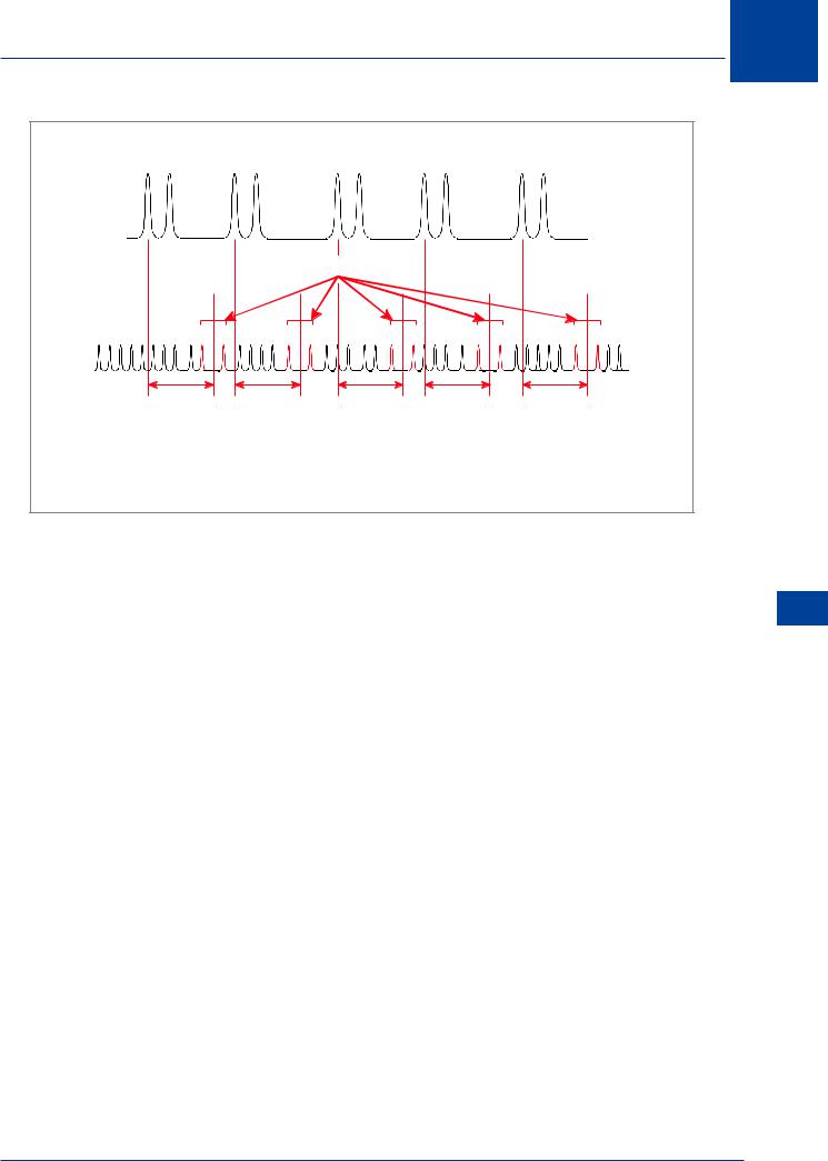
AIRCRAFT’S TRANSMITTED RANDOM PRF
RECEIVER GATE
t |
t |
t |
t |
t |
t = Time between Tx and Rx of twin pulses
Figure 15.8 Acceptance of Own Pulses
Twin Pulses
The use by the DME system of twin pulses ensures that the receivers never accept matching randomized single pulses which could (possibly) emanate from, for example, other radars, ignition systems or lightning.
Range Search
To achieve a rapid lock-on during the range search, the DME interrogator transmits at 150 pulse pairs per second (ppps) for 15 000 pulse pairs (100 seconds).
If lock-on is not achieved, it will then reduce the rate to 60 ppps and maintains this rate until there is a range lock-on. At lock-on the system operates at a random PRF of 27 ppps.
During the range search the range counters, or pointer, of the indicator rotate rapidly from zero nautical miles through to the maximum range; this takes 4 to 5 seconds in modern equipment and 25 to 30 in older systems. If no response is achieved within this period, the pointer, or counters, return rapidly to zero and the search starts again.
Beacon Saturation
The output of a modern ground beacon is a constant 2700 pulse pairs per second which, in the absence of any aircraft interrogations, are generated at random intervals. When a ground beacon is receiving 2700 ppps it becomes saturated and it then reduces its receiver gain. The effect of this is to exclude the transmissions from aircraft whose interrogation pulses are weaker. This equates to about 100 aircraft using the DME at the same time.
Distance Measuring Equipment (DME) 15
249